Thingiverse

SKR 1.4 Turbo X5SA Pro Electronics Package Rev II by Micklen
by Thingiverse
Last crawled date: 3 years, 4 months ago
Revision II of SKR 1.4 Turbo X5SA Pro Electronics Package. Simpler design. Mounts to side of machine.
Video of assembly to be posted here: https://youtu.be/PgnAMK5xNW0
Breakdown of parts as follows:
TFT 35 Case: same as Rev I. Nice design and can be used with any board box.
SKR 1.4 Turbo Board Box:
SKR 1.4 Turbo has same dimensions as SKR 1.4
STL of SKR 1.4 Board was provided by chrstrvs https://www.thingiverse.com/thing:4329049. (Don't need to print.)
Box was designed to attach to support shelf below. And attach to power supply support on side.
Cooling fans bolt to lid and lid bolts to box.
Power Supply Mount:
Included STLs I made of power supply box. Power supply is sized from Tronxy S-360-24 model that came with the printer.
Access lid on power supply allows easy wiring.
Stand (Shelf):
Attaches to 2020 bottom rail with three bolts in side and one in top tab. Front bolt attaches to 2020 riser. Use standard T Nuts and bolts.
Stand includes enclosure for power switch and routing of power and heater wires. Power Switch STL included for modeling purposes (do not need to print).
Various cutouts in design to allow for wire routing and my printer's Z Motor assembly. For standard X5SA Z Motor assembly, you will need to modify cutout or manually cut the printed shelf.
Channels and Back Boxes. (wire channels/conduit/connection points)
Included these as I like to hide/protect all wiring.
Five main channels identified by length. All but 40mm split to print in two pieces. Have tabs to lock them together, but I advise gluing them prior to final assembly.
Four Back Boxes. These are access points where channels terminate to allow for easy wire routing. Two bottom boxes have lids with small tabs on bottom and single screw to hold in place. Small Box on top has a lock tab and screw assembly. Bib Box on top allows for spare wire to be coiled up and hidden.
Rails: (Don't need to print)
Included rails in my modeling to show exact locations of various parts. I included a 2020 and 2040 STL in the files so that others can use them in their own modeling. Plus a complete STL that has all the rails for the unit in one file.
Buck Boxes:
Separate boxes designed to hold 2 Buck Converters each.
Kept them separate from main box as you may or may not need them depending on the power supply/fans used.
I only used one in my arrangement but these can easily be printed and mounted in various locations.
Sized for the type Buck Converter I used. Check your specific dimensions.
Other parts required:
Stand to Frame: 4 M4 10mm, 4 Washers, 4 T-Nuts
Stand Cover: 4 M3 10mm, 4 Washers
Board Box to Stand: 4 M4 10mm, 8 Washers, 4 Nuts
Board Box Cover: 4 M3 10mm, 4 Washers
PS Mount to Board Box: 2 M3 10mm, 4 Washers, 2 Nuts
PS Mount to Stand: 2 M4 10mm, 4 Washers, 2 Nuts
PS to PS Mount/Stand: 2 M4 10mm, 1 M4 8mm, 3 Washers
PS Mount Cover: 4 M3 10mm, 4 Washers
Power Switch to Stand: 1 M3 10mm, 1 M3 20mm, 3 Washers, 1 Nut
Channel Boxes (Back Boxes): 7 M4 10mm, 7 Washers, 7 T-Nuts
Channel Box Covers: 7 M3 10mm, 7 Washers
290mm Channel Riser: 1 M4 10mm, 1 T-Nut, 1 Washer
TOTAL:
20 M4 10mm Bolts
1 M4 8mm Bolt
27 M4 Washers
12 M4 T-Nuts
6 M4 Hex Nuts
22 M3 10mm Bolts
1 M3 20mm Bolt
26 M3 Washers
3 M3 Hex Nuts
See Video for assembly assistance https://youtu.be/PgnAMK5xNW0.
Similar models
thingiverse
free

BIGTREETECH SKR 1.4 Mount for 3030
...s clearance to the mount. mounted to the 3030 frame using m5 bolts and t-slot nuts, the board is mounted using m3 bolts and nuts.
thingiverse
free

SKR 1.4 Case with 80mm fan by frostin2k
...the mounting pads. for the fan you need m4 bolts with nuts or just use screws (6mm or longer).
edit:
use v4.
removed old designs.
thingiverse
free

SKR 1.4 Board holder for 2020 Extrusion
... holder on a 2020 extrusion. requires on only, 4 - m3 x 8mm. and 2 - m4 x 10 mm button top with 2 - t-nut m4 for 2020 extrusions.
thingiverse
free

SKR 1.4 Turbo X5SA Pro Electronics Package by Micklen
...breakdown is covered below: tft 35 case: simple case, similar to the many out there. has mounting bracket and...
thingiverse
free

Screw box M3, M4, M5 by stenc55
...m4 box use m3 or m5, dimensions are the same.
lid is fixed with 2x m3x25 screw.
screws, nuts and washers are not included in .stl
thingiverse
free

MKS Gen 1.4 Kossel Bracket / Mount by Tom90
...rger models.
the spacing for the 2020 mounts is 60mm and is designed for m3 bolts and t-nuts. the board is held down by m4 bolts.
thingiverse
free

Klipper inside box for skr 1.4, skr e3 mini, raspberry pi 3 and lm2596 by igalopaka
... in voron boms). the wall mounting holes are made for m4 bolts.
designed in freecad, the source file is included. happy tweaking!
thingiverse
free

TEVO Turantula Power Supply Box & Mount by limwenyao
...d to mains)
2 x binding post banana plugs
box screw requires
5 x m3 10mm screw
mount requires
2 x m4 10mm screw
2 x m4 t-nuts.
thingiverse
free

Ramps 1.4 Holder for Kossel 2020 near Power Supply by engineer119
...6mm ... 7 sets
ramps 1.3 cooling fan mount for "power supply bracket for kossel 2020http://www.thingiverse.com/thing:1122487
thingiverse
free

Stepper Motor Smoother Board Box by Micklen
...s,
mounting tab to attach box to printer frame (i used an m3 6mm screw and t-nut to attach to 2020 rails on x5sa.
snap fit cover.
Micklen
thingiverse
free

The Child Mando by Micklen
...f "attack position" than "holding".
please do not use for commercial work.
tips are always welcome.
have fun!
thingiverse
free

X5SA Machine Foot Extension by Micklen
...3 30mm and t nuts to attach. print inverted with no supports. 15-20% infill.
should work on any printer with similar sized feet.
thingiverse
free

Wire Box by Micklen
...n in pic.)
can be printed from any non-flexible material as desired. mostly i use pla unless it will be mounted in a heated area.
thingiverse
free
Stepper Motor Smoother Board Box by Micklen
...s,
mounting tab to attach box to printer frame (i used an m3 6mm screw and t-nut to attach to 2020 rails on x5sa.
snap fit cover.
thingiverse
free

Sensor 2 Band by Micklen
... 55 mm axle. band portion of model can be easily lengthened or shortened in modeling software to allow to fit various size axles.
thingiverse
free
SKR 1.4 Turbo X5SA Pro Electronics Package by Micklen
...) you can print the one without post. then print 6 post and glue them in. or just leave them out if you don't need/want them.
X5Sa
thingiverse
free

Chain riser X5SA by xanatorium
...chain riser x5sa by xanatorium
thingiverse
chain risers for x5sa
thingiverse
free

Tronxy X5S X5SA Organizer
...tronxy x5s x5sa organizer
thingiverse
organizer for tronxy x5s; x5sa
thingiverse
free

Tronxy X5SA Z-Blocker by n02m4n
...tronxy x5sa z-blocker by n02m4n
thingiverse
a z-blocker for my x5sa.
thingiverse
free

Tronxy X5SA Fan Duct by Noobik4ever
...tronxy x5sa fan duct by noobik4ever
thingiverse
fun duct for tronxy x5sa
thingiverse
free

Tronxy X5S, X5SA linear rail
...tronxy x5s, x5sa linear rail
thingiverse
linear rail tronxy x5sa
thingiverse
free

Tronxy X5SA Filament holder Screw
...tronxy x5sa filament holder screw
thingiverse
better holder for tronxy x5sa filament as screw
thingiverse
free

TronXY X5SA PRO BLTouch Mount
...tronxy x5sa pro bltouch mount
thingiverse
a simple bltouch mount for the tronxy x5sa pro.
thingiverse
free

Tronxy X5SA Extruder TPU Upgrade
...tronxy x5sa extruder tpu upgrade
thingiverse
redesigned anycubic kossel extruder tpu upgrade for tronxy x5sa
thingiverse
free

X5SA Tronxy Towline by Daelin89
... towline by daelin89
thingiverse
broke the towline on my tronxy x5sa-400. so i remade it in fusion 360. have yet to test print
thingiverse
free

Tronxy X5SA Display Offset by Darkwulf3D
...tronxy x5sa display offset by darkwulf3d
thingiverse
tronxy x5sa pro display offset for the large table adjustment wheels
Skr
turbosquid
$130

Fenerbahce Stadyumu - Skr saracoglu stadium
... available on turbo squid, the world's leading provider of digital 3d models for visualization, films, television, and games.
thingiverse
free

Box SKR V1.3 & SKR V1.4 - Ender 3
...sfrutta il coperchio originale in metallo.
english:
box skr v1.3 and skr 1.4 for ender 3 standard, uses the original metal cover.
thingiverse
free

Mount for the Bigtreetech SKR 1.3
...mount for the bigtreetech skr 1.3
thingiverse
mount for the bigtreetech skr 1.3
thingiverse
free

AM8 box SKR 1.3
...am8 box skr 1.3
thingiverse
box for am8 printer with skr 1.3 and 1 mosfet.
thingiverse
free

SKR TFT35 lid by Foxx_PL
...ingiverse
remixed lid for skr pro xxl coltroller box. it includes place for 80mm fan, skr tft35 and two lm2596 dc-dc converters.
thingiverse
free

Tatara SKR 1.3 case
...tatara skr 1.3 case
thingiverse
modification for skr 1.3 board and tatara frame with 120mm fan.
thingiverse
free

Anycubic Chiron skr mount
...anycubic chiron skr mount
thingiverse
skr 1.3 mount plate for anycubic chiron. for usb drill a hole.
thingiverse
free

SKR E3 DIP box by srprint
...skr e3 dip box by srprint
thingiverse
skr e3 dip
thingiverse
free

BTT SKR v1.1 case by atiszoft
...btt skr v1.1 case by atiszoft
thingiverse
bigtreetech skr v1.1 mainboard case.
thingiverse
free

SKR pro V1.1 Housing
....3 and v1.4 are also available. https://www.youtube.com/watch?v=f7b39z-rley
donation appreciated https://www.paypal.me/klauskorte
Rev
3d_export
$5
Rev Gun 3D Model
...rev gun 3d model
3dexport
rev gun
rev gun 3d model sone93 52014 3dexport
3d_export
$15

Maverick REV-6
...n act as the main blaster of a nerfer, but due to the short range, it is recommended to use it as a secondary, additional weapon.
turbosquid
$84

Euro Pallet rev 2009
... available on turbo squid, the world's leading provider of digital 3d models for visualization, films, television, and games.
turbosquid
$9

Chandra rugs REV-15802
... available on turbo squid, the world's leading provider of digital 3d models for visualization, films, television, and games.
turbosquid
$60

rev"s drum set
... available on turbo squid, the world's leading provider of digital 3d models for visualization, films, television, and games.
3ddd
$1
Sova Design/Rev coffee table
... table
3ddd
журнальный
https://www.facebook.com/media/set/?set=a.514295972031044.1073741841.343660145761295&type;=3
turbosquid
$30

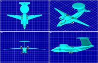
Yak-44 (Rev) AEW Aircraft Solid Assembly Model
... available on turbo squid, the world's leading provider of digital 3d models for visualization, films, television, and games.
turbosquid
$30

Mitsubishi Mu-2 Aircraft Solid Assembly Model(Rev)
... available on turbo squid, the world's leading provider of digital 3d models for visualization, films, television, and games.
turbosquid
$30
An-71 Madcap (Rev) AEW Aircraft Solid Assembly Model
... available on turbo squid, the world's leading provider of digital 3d models for visualization, films, television, and games.
turbosquid
$30

Antonov An-74 (Rev} STOL Transport Aircraft Solid Assembly Model
... available on turbo squid, the world's leading provider of digital 3d models for visualization, films, television, and games.
Ii
3d_ocean
$5
inoplanet II
...inoplanet ii
3docean
3ds arman3dg games ii inoplanet low max poly trees
inoplanet ii
3ddd
$1

Novecento II
...novecento ii
3ddd
консоль
консоль: ii novecento
дизайнер: elia monterosso
3ddd
$1

Спальня VENERO II
...d
venero ii , venero , hulsta
спальня venero ii
3ddd
$1
PROPORTION II
...proportion ii
3ddd
malabar emotional
консоль proportion ii
malabar emotional design
коллекция euphoria
3ddd
$1
Regina II
...ltrona frau , капитоне
this is a custom version of the poltrona frau regina ii armchair.
3d_export
$119

cinderella ii
...cinderella ii
3dexport
3d_export
$119

lara ii
...lara ii
3dexport
3d_export
$119

doris ii
...doris ii
3dexport
3ddd
$1

Heracleum II
...s endless technical possibilities,
making this new version much more efficient while providing unique and sparkling illumination.
3ddd
$1

Towel Collection II
...towel collection ii
3ddd
полотенце
towel collection ii
Electronics
turbosquid
$1

electron
...urbosquid
royalty free 3d model electron for download as max on turbosquid: 3d models for games, architecture, videos. (1157488)
turbosquid
$50

electronic
...
royalty free 3d model electronic for download as max and obj on turbosquid: 3d models for games, architecture, videos. (1289427)
turbosquid
$40

Electron
... available on turbo squid, the world's leading provider of digital 3d models for visualization, films, television, and games.
3d_ocean
$8
Electronic game
...electronic game
3docean
electronic games nu pogody wait a minute well
electronic game “well, wait a minute”, “nu pogody”
3ddd
$1
Brilux Electronic
...brilux electronic
3ddd
подвес. brilux electronic. польша. материалы настроены.
3d_export
free

electronic shop
...lectronic shop with high quality interior and exterior. it has tvs smartphone play station printer and many more electronic item.
3ddd
$1

Термостаты OJ Electronics
...ермостаты oj electronics
3ddd
oj electronics , термостат
термостаты фирмы oj electronics
3d_export
$8

electron 714
...electron 714
3dexport
game ready model for export to unreal engine soviet tv electron 714 pbr 4k
3ddd
$1

Термостат OJ Electronics
... oj electronics
3ddd
oj electronics , термостат
термостат occ2-1991 фирмы oj electronics
turbosquid
$60

Electronics Stuff
...
royalty free 3d model electronics stuff for download as max on turbosquid: 3d models for games, architecture, videos. (1624680)
Package
archibase_planet
free

Package
...package
archibase planet
cat food package
package n190111 - 3d model (*.gsm+*.3ds) for interior 3d visualization.
archibase_planet
free

Package
...package
archibase planet
package dog food petfood
package 2 - 3d model (*.gsm+*.3ds) for interior 3d visualization.
archibase_planet
free

Package
...package
archibase planet
package dog food petfood
package 3 - 3d model (*.gsm+*.3ds) for interior 3d visualization.
archibase_planet
free

Package
...package
archibase planet
package paper bag screw
package n050313 - 3d model (*.gsm+*.3ds) for interior 3d visualization.
archibase_planet
free

Package
...package
archibase planet
package cat food dry cat food
package 4 - 3d model (*.gsm+*.3ds) for interior 3d visualization.
archibase_planet
free

Package
...package
archibase planet
package cat food dry cat food
package 1 - 3d model (*.gsm+*.3ds) for interior 3d visualization.
3d_ocean
$5

Packaging Box
...packaging box
3docean
3dmodel box packaging packaging box
simple packaging box
turbosquid
$19

Package
...turbosquid
royalty free 3d model package for download as max on turbosquid: 3d models for games, architecture, videos. (1372445)
turbosquid
$1

packaging
...osquid
royalty free 3d model packaging for download as blend on turbosquid: 3d models for games, architecture, videos. (1304457)
3ddd
free

package
...package
3ddd
банка
packing design
Pro
turbosquid
$29
Pro
...ree 3d model mac pro for download as obj, c4d, fbx, and blend on turbosquid: 3d models for games, architecture, videos. (1505782)
turbosquid
$15

Apple Mac Pro and Pro Display
...ee 3d model apple mac pro and pro display for download as max on turbosquid: 3d models for games, architecture, videos. (1417078)
3d_export
$5

iphone 13 pro max and pro
...3 pro max and 13 pro the model is made in four colors (graphite, gold, silver, and blue), all of which are attached in the files.
3d_export
free

sapphire pro
...sapphire pro
3dexport
sapphire pro 3d printer head mask
3d_export
$4

macbook pro
...macbook pro
3dexport
macbook pro 13" inch 2020 years model
3ddd
free

GentleLase Pro
... syneron , candela
gentlelase pro аппарат для лазерной эпиляции
turbosquid
$25

PRO frame
...rbosquid
royalty free 3d model pro frame for download as max on turbosquid: 3d models for games, architecture, videos. (1148329)
turbosquid
$5

Alien pro
...osquid
royalty free 3d model alien pro for download as blend on turbosquid: 3d models for games, architecture, videos. (1678446)
turbosquid
$5

iphone11 pro
...uid
royalty free 3d model iphone11 pro for download as blend on turbosquid: 3d models for games, architecture, videos. (1562707)
3ddd
$1

Mac Pro (appel)
...mac pro (appel)
3ddd
компьютер , apple
mac pro
Turbo
turbosquid
$45

TURBOS
... available on turbo squid, the world's leading provider of digital 3d models for visualization, films, television, and games.
turbosquid
$45

TURBOS
... available on turbo squid, the world's leading provider of digital 3d models for visualization, films, television, and games.
design_connected
$13

Turbo
...turbo
designconnected
gubi turbo computer generated 3d model. designed by weisdorf, louis .
3d_export
$5

turbo
...turbo
3dexport
representation of an automotive turbine.
3d_ocean
$7

Turbo
...bo from the movie turbo.modeled in 3ds max 2014. 3d file formats included : max 2014 max 2011 obj fbx please rate when you buy :
turbosquid
$90

Turbo engine
... available on turbo squid, the world's leading provider of digital 3d models for visualization, films, television, and games.
turbosquid
$5

Blue turbo
... available on turbo squid, the world's leading provider of digital 3d models for visualization, films, television, and games.
turbosquid
$3

Turbo Truck
... available on turbo squid, the world's leading provider of digital 3d models for visualization, films, television, and games.
turbosquid
free

Turbo kit
... available on turbo squid, the world's leading provider of digital 3d models for visualization, films, television, and games.
3ddd
$1
Turbo Racing
... машинка
игрушечная гоночная дорога "turbo racing". почувствуй себя настоящим гонщиком.
4
turbosquid
$9

Office Chair 4-4
... available on turbo squid, the world's leading provider of digital 3d models for visualization, films, television, and games.
3d_export
$5

doors- 4
...doors- 4
3dexport
doors 4
3d_export
$5
hinge 4
...hinge 4
3dexport
hinge 4
3ddd
$1

Штора №4
...штора №4
3ddd
штора №4
3d_export
free

playstation 4
...playstation 4
3dexport
playstation 4
turbosquid
$1

re 4-4 electric locomotive
... free 3d model re 4 4 electric locomotive for download as obj on turbosquid: 3d models for games, architecture, videos. (1707845)
3ddd
$1

nexus 4
...nexus 4
3ddd
lg , телефон
nexus 4
3ddd
$1
4 Poufs
...4 poufs
3ddd
пуф
4 soft poufs
turbosquid
$12

Calligraphic Digit 4 Number 4
...hic digit 4 number 4 for download as max, obj, fbx, and blend on turbosquid: 3d models for games, architecture, videos. (1389332)
3ddd
$1
Dauphin 4+
...dauphin 4+
3ddd
кресло
dauphin 4+ конференц кресло
1
turbosquid
$69

armchairs(1)(1)
... available on turbo squid, the world's leading provider of digital 3d models for visualization, films, television, and games.
turbosquid
$15

ring 1+1
... available on turbo squid, the world's leading provider of digital 3d models for visualization, films, television, and games.
turbosquid
$10

chair(1)(1)
... available on turbo squid, the world's leading provider of digital 3d models for visualization, films, television, and games.
turbosquid
$8

Chair(1)(1)
... available on turbo squid, the world's leading provider of digital 3d models for visualization, films, television, and games.
turbosquid
$2

RING 1(1)
... available on turbo squid, the world's leading provider of digital 3d models for visualization, films, television, and games.
turbosquid
$1
house 1(1)
... available on turbo squid, the world's leading provider of digital 3d models for visualization, films, television, and games.
turbosquid
$1

Table 1(1)
... available on turbo squid, the world's leading provider of digital 3d models for visualization, films, television, and games.
turbosquid
$59

Formula 1(1)
...lty free 3d model formula 1 for download as max, fbx, and obj on turbosquid: 3d models for games, architecture, videos. (1567088)
design_connected
$11

No 1
...no 1
designconnected
sibast no 1 computer generated 3d model. designed by sibast, helge.
turbosquid
$2
desert house(1)(1)
...3d model desert house(1)(1) for download as 3ds, max, and obj on turbosquid: 3d models for games, architecture, videos. (1055095)