Thingiverse
Silent Wall and Desk Clock by mariust
by Thingiverse
Last crawled date: 2 years, 10 months ago
Silent Clock
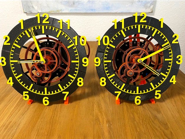
This is a silent Clock for wall mounting or to place on a flat surface. It is designed from the ground up to be easily printed so you should have no problem with it - only a single part needs supports (the wall hanger). The maximum required print area is 180 mm x 180 mm (I used my Prusa mini as upper limit)
The clock is designed around common parts readily available online like a 5V Stepper motor, a Arduino nano and a common RTC and bearings. A more specialized component is the silent step stick which is the ultra quiet stepper driver. However you can try these common stepper drivers for 3d printers and see if they are sufficiently quiet.
Many of the parts are designed to support two-color printing via M600 command (changing filament mid print) by incorporating stepped design accents (mostly the gears and the clock face). For materials you can print everything in PLA if you wish. I myself printed the Wall Hanger (M25), the cable strain relief (M28) and the legs (M26, M27) in PETG. The remainder was mostly printed in galaxy black and pineapple yellow PLA.
I'm not an artist, I tried my best to create something simple but neat looking. If you want to make your own clock face I can create a drawing with the required mounting points.
For the two or three people in the world which like me prefer a counter clockwise spinning clock there is a variant of the clock face in the files folder. To spin the clock backwards only a single line in the code has to be edited.
The clock is set by disengaging the spring loaded gear of the stepper motor and tuning the handles manually. The RTC clock chip is only used as very precise 1 Herz Clock source.
Part List
All components have an identifiers. Parts to buy have the prefix "B" and all parts you have to make/print are marked with the prefix "M". The screw types are not very well optimized, I just used what I had at hand at the time. At some parts you may get away with shorter/longer bolts.
I hope you can overlook the frequent occurrence of "watchface", I only found out later that this is not an actual English word - sorry about that.
The fact that M20 is called Battery holder can be ignored for now. In theory this clock can be conveniently battery powered, however the run time is still way too bad. Maybe I will release a retro-fit design in a few moths to fix that and make battery powered operation feasible.
Parts to buy
Part Number
Quantity
Part Name
Description
B01
5
B01_Bearing7/22/8
Standard Bearing
B02
1
B02_Stepper_Motor
Stepper Motor 28BYJ-48 ULN2003
B03
1
B03_Arduino_nano
Arduino Nano
B04
1
B04_Stepper_driver
Silent Step Stick
B05
1
B05_RTC_PCB
Real Time Clock AZDelivery RTC DS3231
B06
1
B06_coil_tensioned
Small coil
B07
2
B07_M5x20
M5x20 Screw, any head
B08
1
B08_M5x24
M5x24 Screw, any head
B09
1
B09_M5x35
M5x35 Screw, any head
B10
2
B10_M4x8_flathat
M4x8 Screw, flat head
B11
13
B11_M4x10_flathat
M4x10 Screw, any head
B12
1
B12_M3x30
M3x30 Screw, any head
B13
32
B13_M3x12
M3x12 Screw, any head
B14
6
B14_M3x8
M3x8 Screw, flat head
B15
2
B15_M3_washer
M3 Washer
B17
2
B17_M2x8_flathat
M2x8 Screw, flat head
Parts to print
Part Number
Quantity
Part Name
Description
M01
1
M01_Base
Base Plate of the device
M02
1
M02_gear_a
Gear a
M03
1
M03_gear_b1
Gear b1
M04
1
M04_gear_b2
Gear b2
M05
1
M05_gear_c1
Gear c1
M06
1
M06_gear_c2
Gear c2
M07
1
M07_gear_d1
Gear d1
M08
1
M08_gear_d2
Gear d2
M09
1
M09_gear_e
Gear e
M10
4
M10_Bearing_cap_M5
Cap to screw in M5 bolt
M11
1
M11_Motor_arm
Arm to swivel the stepper motor
M12
1
M12_Motor_mount
Part to mount the stepper motor
M13
1
M13_mount_stand_gears_d
Connects base with d-gear mount
M14
1
M14_mount_arm_gears_d
Holds in place bearing of d-gears
M15
1
M15_e_bearing_adapter
Standoff to mount minute handle to gear
M16
9
M16_WF_Holder
Holds the Watchface in place
M17
3
M17_WF_clamp
Watchface Mounting gear
M18
1
M18_WF_TRBR_clamp
Clamp to fix watchface sub-parts
M19a
1
M19CW_c_Watchface_BR
Watchface top right
M19b
1
M19CW_a_Watchface_TL
Watchface botton right
M19c
1
M19CW_d_Watchface_BL
Watchface bottom left
M19d
1
M19CW_b_Watchface_TR
Watchface top left
M20
1
M20_Battery_Holder_Mount
Mouting Point for PCBs and Batteries
M21
1
M21_PCB_mount_Arduino
Mount for the Arduino nano
M22
1
M22_PCB_mount_RTC_Stepperdriver
Mount for RTC and Stepperdriver
M23
1
M23_Handle_h
Hour Handle
M24
1
M24_Handle_m
Minute Handle
M25
1
M25_Wall_mount
Wall Hanger
M26
1
M26_Desk_Stand_Left
Desk Stand Left
M27
1
M27_Desk_Stand_Right
Desk Stand Right
M28
1
M28_Cable_clamp
Strain relief for USB cable
Parts which can be printed together in one operation:
M02_M03_M04_M06_M07_M08_M09
M10_M12_M13_M14_M15_M20_M21_M22
M16_M17_M18
Additional parts
USB Cable to power the clock (USB 2.0 is sufficient)
USB Charger
maybe two small felt pads to not scratch the wall painting when wall mounting
The current draw is less than 500mA so any USB charger should work
Prerequisites to build this clock:
Soldering iron
Basic electronics skills to wire everything up
Knowledge on how to flash an Arduino with the provided code
M3, M4 and M5 thread cutting taps
Small wires to interconnect the electronic components
Pliers and scalpel or small box cutter to cut PCB trace of stepper motor (see Assembly Note 1)
Small flat head screwdriver and Multimeter to adjust motor current
Assembly
https://youtu.be/mQPGC7IA-mg
I created an animation which shows step by step how to assemble the clock. It is quite fast paced, just pause it at every step. In the video there are a few callouts to Assembly notes, these are covered here:
Assembly Note 1:
Stepper Motor Modification:
To make the clock as quiet as possible the normally unipolar stepper motor 28BYJ-48 ULN2003 is modified to be bipolar. João Brázio from the website Ardufocus shows how to do it. Basically you want to cut a single PCB trace (check with multimeter afterwards that the trace is cut)https://ardufocus.com/howto/28byj-48-bipolar-hw-mod/
You can remove the end of the cable with the connector, we don't need it, as well as the red cable in its entirety.
Assembly Note 2:
Wire up Arduino, Stepper driver and stepper motor.
Face the Arduino with its USB plug upwards (as in the video) and face the motor connections of the silent step stick in the direction of the stepper motor (M1A .. M2B). Connect the wires as shown in the wiring diagram:
Arduino
Stepper Driver
Stepper Motor
D11
EN
D12
DIR
D13
STEP
3V3
VIO
5V
VM
GND
GND near VM
M2B
Dark Yellow
M2A
Pink
M1A
Bright Yellow
M1B
Blue
Optionally you can remove the small resistor besides the red pwr LED so that the Arduino does not glow in the dark (recommended).
Assembly Note 3:
Wire up the RTC:
First, if you bought the cheap AZDelivery RTC DS3231 like me with a battery instead of an rechargeable battery you want to remove the diode between the IC and the four-pin connector. A forced charging with this diode of a non-rechargeable battery is a fire hazard.
We have to cut off the six-pin pinheader because the RTC would otherwise be too tall to fit under the clock face. Remove the battery while doing so to prevent accidental shortcuts. Plug the battery back in after removing the pinheader.
Now you can wire up the RTC:
Arduino
Stepper Driver
RTC
D2
---
SQW
A4
---
SDA
A5
---
SCL
---
GND near VIO
GND
---
VIO
VCC
Optionally you can remove the small resistor besides the red pwr LED so that the RTC does not glow in the dark (recommended).
Now is also a good time to flash the Arduino with the provided firmware:https://github.com/mariuste/SilentWallandDeskClock
Shout-outs:
I want to thank Nico Schlueter for providing the awesome free gear making plugin "Helical Gears Plus" for Fusion 360. I created all gears in this design with it:https://apps.autodesk.com/FUSION/en/Detail/Index?id=1259509007239787473&os=Win64&appLang=en
For preparing the release of this design I used the Fusion 360 Plugin Bommer by Jesse Rosakia and James Ray extensively. As the name implies it is very useful to create semi complex Bills of Material which allowed me to track my progress in various stages of the design.
To safe some time I used the following libraries in my code. They are available in the Arduino library manager"StepperDriver" by Laurentiu Badea v1.3.1
Info: https://github.com/laurb9/StepperDriver
"DS3231" by Andrew Wickert, Eric Ayars, Jean-Claude Wippler, Northern Widget LLC v1.0.7
Info: https://github.com/NorthernWidget/DS3231
Similar models
thingiverse
free

Arduino Digital Clock by Basti13
...h button for backlight
lipo battery
some wires
micro usb lipo charger board
i will add link for the arduino code later!
thingiverse
free

0.96" mini clock by mkchung22
...tery charge board x 1
3.7v 1000ma lithium battery x 1
main switch x 1
push button x 1
ds3231 rtc x 1
https://youtu.be/xqsle3soqjk
grabcad
free

DS3231 RTC Module
...ds3231 rtc module
grabcad
ds3231 rtc module for arduino or raspberry pi
thingiverse
free

Googly eyed Minion clock by KiwiGrinder
...s to take 28byj-48 stepper motors, my suggestion to you would be to mount them near the back and put the eyeballs on long shafts.
thingiverse
free

60flaps * 2drums split flap display clock by itoshin
...t2tuigjosqwhttp://www.instructables.com/id/byj48-stepper-motor/http://www.instructables.com/id/real-time-clock-using-ds3231-easy/
thingiverse
free

LOL Clock by robaux
...shield 3mm
1 x arduino/genuino uno board
1 x rtc ds3231 modul
4 x m3 screw & nut
firmware:https://github.com/robaux/lolclock/
thingiverse
free

Hollow clock 2 - silent and smooth by shiura
... with 8-phase control.
update mar 3, 2021
cover for the rear parts (stepper motor, circuits) is added. it needs support to print.
grabcad
free

RTC DS3231 with Battery on Top
...rtc ds3231 with battery on top
grabcad
this 3d model is a 3d model for rtc ds3231 with battery on the top
thingiverse
free

Second Arduino Clock
... and others.
included in the thing files is a text file with the code for the arduino.
look for: arduinocodesecondclockbutton.rtf
thingiverse
free

USB type B surface mount for Arduino by Droopas
...p 2:
solder wires from arduino to usb connector. glue usb connector to housing.
step 3:
mount in project box with 2 screws. done!
Mariust
thingiverse
free

Spool Adapter for Filament Holders by mariust
... to hold your spool in place.
the default values work with a m8 threaded rod, but all values can be adjusted with the customizer.
thingiverse
free

Panel Due Mount by mariust
...e screwholes are meant for a mountin bracket like this one: http://www.amazon.com/dp/b01md29v3x/ref=cm_sw_r_tw_dp_x_o0j6ybcxmd3dz
thingiverse
free

Optical Entstop Holder for 3KU Delta Printer by mariust
...e print settings are uncritically. i designed it because i didn't like the huge mechanical endstops of the 3ku delta printer.
thingiverse
free

Felix Printer Filament Guide (straight + bent) by mariust
... a ball bearing.
i got some inspiration from the filament guides by vyndalin (i recreated the clipping part with my cad program).
thingiverse
free

Duet WiFi Mount for 3KU Delta Printer by mariust
...ay to mount the panel due (the lcd screen of the duet wifi) have a look at my lcd mount: http://www.thingiverse.com/thing:2237840
thingiverse
free

Top Fan Mount for 3KU Delta Printer by mariust
...ntpart("nw");
printpart("ne");
//printpart("sw");
//printpart("se");
//printpartwmount();
thingiverse
free

E3D 6 Lite Effector for 3KU Delta Printer with BLTouch mount by mariust
...ow because i will have to recreate the whole thing (i don't have access to the solidworks licence of my university any more).
thingiverse
free

Tap-O-Mat - M3/M4/M5/M6 Thread Cutter/Tap to Drill-Bit Adapter by mariust
... or petg.
screws i used:
2x m5x16 with a hex-head
2x m5 wing nuts
optional but recommended to fix the clamps:
2x m3x8 countersunk
Silent
3d_export
$5

silent
...silent
3dexport
nunchuck , jagdkommando and shuriken
turbosquid
free

Eyes of silent laughter
...ree 3d model free eyes of silent laughter for download as max on turbosquid: 3d models for games, architecture, videos. (1632751)
turbosquid
$20

silent monkey 003
... available on turbo squid, the world's leading provider of digital 3d models for visualization, films, television, and games.
turbosquid
$19

set12 - Silent rush
... available on turbo squid, the world's leading provider of digital 3d models for visualization, films, television, and games.
turbosquid
$9

Silent Notary black coin
...ty free 3d model silent notary black coin for download as max on turbosquid: 3d models for games, architecture, videos. (1626772)
turbosquid
$9

Silent Notary cold coin
...lty free 3d model silent notary cold coin for download as max on turbosquid: 3d models for games, architecture, videos. (1626771)
turbosquid
$15

Silent Hill Pyramidhead Sword
...hill pyramidhead sword for download as 3ds, max, obj, and fbx on turbosquid: 3d models for games, architecture, videos. (1408655)
turbosquid
$49

Makarov PB Silent Pistol
... available on turbo squid, the world's leading provider of digital 3d models for visualization, films, television, and games.
cg_studio
$30

Silent Night Wall Clock3d model
...o
.3ds .dxf .fbx .max .obj - silent night wall clock 3d model, royalty free license available, instant download after purchase.
3d_export
$11

norse silent hill rigging nude
...norse silent hill rigging nude
3dexport
Clock
3d_ocean
$4

Clock
...clock
3docean
clock hand kitchen clock time watch
a clock
archibase_planet
free

Clock
...clock
archibase planet
clock table clock alarm-clock
clock orange - 3d model (*.gsm+*.3ds) for interior 3d visualization.
archibase_planet
free

Clock
...clock
archibase planet
clock table clock alarm-clock
clock yellow - 3d model (*.gsm+*.3ds) for interior 3d visualization.
archibase_planet
free
Clock
...clock
archibase planet
clock alarm-clock
clock n100707 - 3d model for interior 3d visualization.
archibase_planet
free

Clock
...clock
archibase planet
clock table clock
clock - 3d model (*.gsm+*.3ds) for interior 3d visualization.
archibase_planet
free

Clock
...clock
archibase planet
clock striking clock
clock - 3d model (*.gsm+*.3ds) for interior 3d visualization.
archibase_planet
free

Clock
...clock
archibase planet
clock wall clock
clock 1 - 3d model (*.gsm+*.3ds) for interior 3d visualization.
archibase_planet
free
Clock
...clock
archibase planet
clock wall clock
clock 2 - 3d model (*.gsm+*.3ds) for interior 3d visualization.
archibase_planet
free

Clock
...clock
archibase planet
clock wall clock
clock 3 - 3d model (*.gsm+*.3ds) for interior 3d visualization.
archibase_planet
free

Clock
...clock
archibase planet
alarm clock alarm-clock
clock - 3d model (*.gsm+*.3ds) for interior 3d visualization.
Desk
3d_ocean
$6

Desk
...desk
3docean
bureau desk desktop office plywood study table work desk writing
a desk made of plywood
3d_ocean
$8

Desk
...oom or university. it can be used as an office desk or as a teacher’s desk, for example. the layer names are self explanatory....
3d_export
$5

Desk
...desk
3dexport
desk
3d_export
$5

Desk
...desk
3dexport
desk
3d_export
$5

desk
...desk
3dexport
desk
3d_export
$5

desk
...desk
3dexport
desk
3d_export
free

desk
...desk
3dexport
desk
3d_export
free

desk
...desk
3dexport
desk
3d_export
$5

desk
...desk
3dexport
computer desk
archibase_planet
free

Desk
...rchibase planet
bureau desk writing-desk
desk giorgetti epi 51610 n231010 - 3d model (*.gsm+*.3ds) for interior 3d visualization.
Wall
turbosquid
$5

Wall and UDK Wall
... available on turbo squid, the world's leading provider of digital 3d models for visualization, films, television, and games.
archibase_planet
free

Wall
...wall
archibase planet
batten wall plywood partition
batten wall - 3d model for interior 3d visualization.
3d_ocean
$5

Wall
...wall
3docean
low polgon wall low stone old wall stone wall
2048*2048 tex obj,fbx,blend format. low polygon. game ready.
3ddd
$1

wall
...wall
3ddd
камень , кладка
damaged stone wall
3d_export
$5

wall
...wall
3dexport
room with a wall with doors made of wood and leather
3ddd
$1

WALL FREAMS
...wall freams
3ddd
wall freams
wall freams
3ddd
$1

WALL-E
...wall-e
3ddd
wall-e , робот
wall-e
3ddd
$1

WALL PANNEL
...wall pannel
3ddd
панель
wall pannel for enterance wall.
3d_export
$18

great wall-city wall-dianjiangtai
...great wall-city wall-dianjiangtai
3dexport
great wall-city wall-dianjiangtai<br>3ds max 2015
turbosquid
$5

Wall
...wall
turbosquid
royalty free 3d model wall for download as on turbosquid: 3d models for games, architecture, videos. (1522889)