Thingiverse

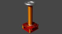
SG Energizer with a Large Coil (Bedini) by Cotton80
by Thingiverse
Last crawled date: 3 years ago
https://www.youtube.com/watch?v=ixBTwQjipr4
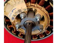
This is a mechanical resonant energizer made to experiment with radiant energy. John Bedini received patents in the recovery and regauging of radiant energy through this type of device. I would encourage you to learn about this technology through this website: http://www.energyscienceforum.com/forumdisplay.php?f=48
The moderators worked closely with Bedini and are well versed in this technology.
About this specific device:
I used all pla for the printed parts.
The magnets are the Harbour Freight variety: 1 7/8 X 7/8 X 1/2
The wheel is a 77mm skateboard wheel.
The rod through the wheel is 8mm
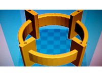
The coil is two piece. I used Loctite 5sec superglue to adhere the top to the base.
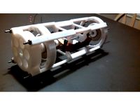
The top of the coil is used to secure the rotor (skate wheel). I provided a print file to make securing the magnets easy but you can just evenly glue the magnets around a bare wheel. The height of the wheel is adjustable with the (4) 1/4" X 4" threaded rod pieces. The center of the coil is a 7/8" circle where you can fill with the traditional copper coated welding wire or the soft steel shot. The coil inner height is 4". It can fit up to 3.75" in diameter of wire around it. If you use the 7 strands of #20 and 1 strand of #23 magnet wire as suggested in http://bedinisg.com/?hop=energysci, you will be able to use 200' of each of those strands twisted together. If you need a circuit to run your device I recommend this website: http://teslagenx.com/kits.html
1/2" X 1" bolts (4) on the base connects the coil.
6-32 X 1.75" bolts connects the coil cover together.
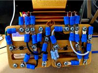
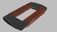
In the pictures you see that only one coil is used. You can make brackets (file not provided) to add to the base and make a four quadrant (coil) system.
You can exchange the metal rods/bolts for nylon for superb performance.
http://www.energyscienceforum.com/showthread.php?t=3888
Disclaimer: Experiment at your own risk. Catastrophic failure of parts spinning at high speed can cause damage to property, injury, or even death. This project contains an electrical function. Electrical shock resulting in injury or death can occur. If you are not experienced with working with electricity do not attempt this project. Know that some frequencies have been speculated to cause cellular disruption leading to cancer.
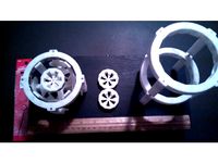
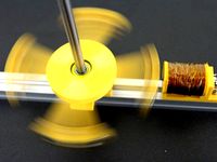
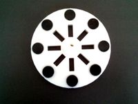
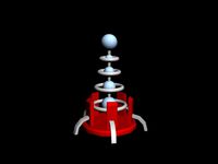
10/02/2017 I added a magnet rotor with the magnets covered. I still recommend using glue additionally. The holes are for a future pulley attachment.
10/03/2017 I added the rotor wheel ends w/ pulley, rod holder to accommodate, and stand-offs to match. The bolt holes for the wheel covers w/ pulley is 6-32 X 1". The new holes on the rod holder are for 8-32 threaded rod. That is for any add-on that you wish to install. My plan is to add a timing wheel/flywheel above the skate wheel to be driven by the pulley.
10/13/2017 I added the speed reduction pulley system for the capacitor dump. This video should clarify parts positioning for you: https://www.youtube.com/watch?v=0cFmwtLZslo. The cam end cap has only one cam. I may add a two and three cam end cap in the future. The printed parts on the small pulleys fit over 53mm skateboard wheels. The caps for the wheels are attached with 6-32 X 3/4" bolts. Use the provided bearing stand-offs file used for the big wheel to cut and size as you need for the small pulley. I use a razor and hammer to guillotine the tubes to chop them. I print all of my parts with 1.2mm walls and .8mm to and bottom layers. Some sanding and drilling may be required for smooth fits.
This is a mechanical resonant energizer made to experiment with radiant energy. John Bedini received patents in the recovery and regauging of radiant energy through this type of device. I would encourage you to learn about this technology through this website: http://www.energyscienceforum.com/forumdisplay.php?f=48
The moderators worked closely with Bedini and are well versed in this technology.
About this specific device:
I used all pla for the printed parts.
The magnets are the Harbour Freight variety: 1 7/8 X 7/8 X 1/2
The wheel is a 77mm skateboard wheel.
The rod through the wheel is 8mm
The coil is two piece. I used Loctite 5sec superglue to adhere the top to the base.
The top of the coil is used to secure the rotor (skate wheel). I provided a print file to make securing the magnets easy but you can just evenly glue the magnets around a bare wheel. The height of the wheel is adjustable with the (4) 1/4" X 4" threaded rod pieces. The center of the coil is a 7/8" circle where you can fill with the traditional copper coated welding wire or the soft steel shot. The coil inner height is 4". It can fit up to 3.75" in diameter of wire around it. If you use the 7 strands of #20 and 1 strand of #23 magnet wire as suggested in http://bedinisg.com/?hop=energysci, you will be able to use 200' of each of those strands twisted together. If you need a circuit to run your device I recommend this website: http://teslagenx.com/kits.html
1/2" X 1" bolts (4) on the base connects the coil.
6-32 X 1.75" bolts connects the coil cover together.
In the pictures you see that only one coil is used. You can make brackets (file not provided) to add to the base and make a four quadrant (coil) system.
You can exchange the metal rods/bolts for nylon for superb performance.
http://www.energyscienceforum.com/showthread.php?t=3888
Disclaimer: Experiment at your own risk. Catastrophic failure of parts spinning at high speed can cause damage to property, injury, or even death. This project contains an electrical function. Electrical shock resulting in injury or death can occur. If you are not experienced with working with electricity do not attempt this project. Know that some frequencies have been speculated to cause cellular disruption leading to cancer.
10/02/2017 I added a magnet rotor with the magnets covered. I still recommend using glue additionally. The holes are for a future pulley attachment.
10/03/2017 I added the rotor wheel ends w/ pulley, rod holder to accommodate, and stand-offs to match. The bolt holes for the wheel covers w/ pulley is 6-32 X 1". The new holes on the rod holder are for 8-32 threaded rod. That is for any add-on that you wish to install. My plan is to add a timing wheel/flywheel above the skate wheel to be driven by the pulley.
10/13/2017 I added the speed reduction pulley system for the capacitor dump. This video should clarify parts positioning for you: https://www.youtube.com/watch?v=0cFmwtLZslo. The cam end cap has only one cam. I may add a two and three cam end cap in the future. The printed parts on the small pulleys fit over 53mm skateboard wheels. The caps for the wheels are attached with 6-32 X 3/4" bolts. Use the provided bearing stand-offs file used for the big wheel to cut and size as you need for the small pulley. I use a razor and hammer to guillotine the tubes to chop them. I print all of my parts with 1.2mm walls and .8mm to and bottom layers. Some sanding and drilling may be required for smooth fits.
Similar models
thingiverse
free
Magnetically Levitated Bedini/Cole Window Pulse Motor by Cotton80
...45
https://www.youtube.com/watch?v=p0tj8u7_qmi
the rotor was redesigned so that the magnets are no longer exposed on the outside.
thingiverse
free
Pulse Motor(s) for Zero Back emf Experiment by Cotton80
.... you will need to use support on the coil piece and rotor. with the adapter horizontally stacking multiple motors are possible.
thingiverse
free

Bedini rotor by Syngenta
...dermagnet-200-x-200-x-30-mm-n45-nickel-m3-senkloch::511.html
(german shop)
coils and other rotors for a bedini are in my library.
grabcad
free

Bedini rotor
...dermagnet-200-x-200-x-30-mm-n45-nickel-m3-senkloch::511.html
(german shop)
coils and other rotors for a bedini are in my library.
thingiverse
free
Magnetic Suspension Motor/Generator by Cotton80
...xperiment at your own risk. catastrophic failure of parts spinning at high speed can cause damage to property, injury, or death.
thingiverse
free

Bedini SG style motor (mechanical components) by MrCadillacsts
...tl will be glued to the lower side of the mounting plate.
add your bedini circuit and start the motor!!
have fun with this kit!!!
thingiverse
free
Bedini SSG Solderless Circuit by Cotton80
...elp reduce print time and still remains functional.
i also added a stencil for those who may want to put your circuit on a board.
thingiverse
free
Zero Force Motor Attachment for: http://www.thingiverse.com/thing:2149044 by Cotton80
...=1023
3/5/2017: i added a third option for a rotor. you will be able to fit up to a 3/4" x 3/4" magnet in the slots.
thingiverse
free
Let's make your own Bedini Motor by arnoldkorea
...e spindle)
1 x m3 bolt (m3x50)
8 x m3 bolt (m3x20)
12 x m3 nut
make your own bedini motor circuit and play with fun !!
grabcad
free

bedini rotor
...ni are in my library. the holes are perfect for 20mm 6mm thick ring magnets.the cover is put onto the magnets for safety reasons.
Cotton80
thingiverse
free
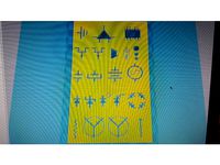
Electronic Symbol Stencils (Basic) by Cotton80
...your pencils. this is two basic stencils to assist with drawing your electronic circuit schematic. they are .8mm thick. enjoy!
thingiverse
free
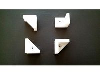
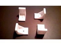
Bracket 3-Point by Cotton80
... to whatever dimensions you like.
disclaimer: use this part in your build at your own risk. load test have not been performed.
thingiverse
free
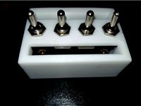
Toggle Switch Mounts (2 or 4) by Cotton80
... in one side for wire access.
also not pictured is 4 mounting holes for 6-32 bolts. they will need to be at least 1.5" long.
thingiverse
free
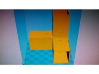
Bracket 90 Degree L by Cotton80
...able tops, securing chair seats
disclaimer: use this part in your creation at your own risk. load test have not been performed.
thingiverse
free
Bedini SSG Solderless Circuit by Cotton80
...elp reduce print time and still remains functional.
i also added a stencil for those who may want to put your circuit on a board.
thingiverse
free
Coupler for 1" Aluminum Square Tube (3-Way) by Cotton80
... support for the two horizontal tube sections.
disclaimer: use this object at your own risk. load test have not been performed.
thingiverse
free
Bearing Hub for PMSM by Cotton80
...en working with electrical equipment, especially when working with capacitors. do not attempt without good electrical knowledge.
thingiverse
free
Magnet Stator for a Mini Windmill Style Generator by Cotton80
...ill bit through the piece to ensure a good fit.
this thing can be scaled up to 200% to fit a 1/2" shaft and 1" magnets.
thingiverse
free

3/4" Rod Holder by Cotton80
...on top to make a light weight shelf. you can use the keyhole hangers to hang pictures in the open instead of directly on a wall.
thingiverse
free
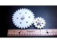
Spur Gears: 1 to 2 Ratio for 1/4" or 8mm shaft by Cotton80
...an easy fit.
the large gear has 28t and the small gear has 14t.
added on 02/05/2017: gears together for 1/4" & 8mm shaft
Bedini
thingiverse
free
Bedini rotor by Syngenta
...ni are in my library. the holes are perfect for 20mm 6mm thick ring magnets.the cover is put onto the magnets for safety reasons.
thingiverse
free

ReDesign3DP Bedini Motor V1 by redesign3dp
...redesign3dp bedini motor v1 by redesign3dp
thingiverse
redesigned bedini motor
thingiverse
free

Bedini Rotor round by Syngenta
...ngenta
thingiverse
this is the round version of my bedini rotor. magnets with 20mm diameter and 7mm in depth fit into the holes.
thingiverse
free
Bedini rotor by Syngenta
...dermagnet-200-x-200-x-30-mm-n45-nickel-m3-senkloch::511.html
(german shop)
coils and other rotors for a bedini are in my library.
thingiverse
free

Optical Tachometer for Bedini 3-pole Kit by liquidbuddha
...istor, with 5mm led plastic holders (both from radio shack). there is a small channel for wires, for the back side led or sensor.
thingiverse
free
Let's make your own Bedini Motor by arnoldkorea
...e spindle)
1 x m3 bolt (m3x50)
8 x m3 bolt (m3x20)
12 x m3 nut
make your own bedini motor circuit and play with fun !!
thingiverse
free
Bedini SSG Solderless Circuit by Cotton80
...elp reduce print time and still remains functional.
i also added a stencil for those who may want to put your circuit on a board.
thingiverse
free

Bedini-Type 6-Pole Magnet Motor by Syrus54
...the size to fit the application.
item is not for sale, royalty free.
[ do not sell nor re-distribute my work ]
you're welcome
thingiverse
free

electric coil by Syngenta
...by syngenta thingiverse this coil is perfect for a bedini pulse motor, the little hole is perfect for 2mm...
thingiverse
free
Bedini SG style motor (mechanical components) by MrCadillacsts
...tl will be glued to the lower side of the mounting plate.
add your bedini circuit and start the motor!!
have fun with this kit!!!
Energizer
turbosquid
$25
energizer
... available on turbo squid, the world's leading provider of digital 3d models for visualization, films, television, and games.
turbosquid
free
Energizer
... available on turbo squid, the world's leading provider of digital 3d models for visualization, films, television, and games.
turbosquid
$12

Energizer Display Stand
...nergizer display stand for download as max, 3ds, fbx, and obj on turbosquid: 3d models for games, architecture, videos. (1695702)
turbosquid
$5
Energizer 9V Battery
...l energizer 9v battery for download as 3ds, max, obj, and fbx on turbosquid: 3d models for games, architecture, videos. (1296932)
turbosquid
$5
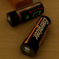
AA Battery Energizer
... available on turbo squid, the world's leading provider of digital 3d models for visualization, films, television, and games.
turbosquid
free
Energizer Battery Charger
... available on turbo squid, the world's leading provider of digital 3d models for visualization, films, television, and games.
3d_export
$25
Energizer D Battery 3D Model
... energy torch poweraa battery amp resistance electricity cell duracell
energizer d battery 3d model 3dillustration 23588 3dexport
3d_export
$25
Energizer AAA Battery 3D Model
...nergy torch poweraa battery amp resistance electricity cell duracell
energizer aaa battery 3d model 3dillustration 23587 3dexport
3d_export
$25
Energizer AA Battery 3D Model
...energy torch poweraa battery amp resistance electricity cell duracell
energizer aa battery 3d model 3dillustration 23586 3dexport
3d_export
$25
Energizer C Battery 3D Model
... energy torch poweraa battery amp resistance electricity cell duracell
energizer c battery 3d model 3dillustration 23589 3dexport
Sg
3ddd
$1

Latina SG
...latina sg
3ddd
барный
стул барный latina sg
3ddd
$1

SGS / OZ
...sgs / oz
3ddd
sgs
http://www.ceramicagsg.com/washbasins-and-shower-tray-oz/washbasin-oz.html
3d_export
$5

electric guitar sg
...electric guitar sg
3dexport
3d model electric guitar sg.
design_connected
$18

SG Padded Vases
...sg padded vases
designconnected
smallaccents sg padded vases computer generated 3d model.
turbosquid
$21

Gibson SG
... available on turbo squid, the world's leading provider of digital 3d models for visualization, films, television, and games.
turbosquid
free

Gibson SG
... available on turbo squid, the world's leading provider of digital 3d models for visualization, films, television, and games.
3ddd
$1

Suffolk | SG-1260
...g-1260
3ddd
urban electric
the urban electric
suffolk sg-1260
lustrehttp://www.urbanelectricco.com/mobile/suffolk.html
3ddd
$1

Kolarz Maschera 0228.62.SG
...kolarz maschera 0228.62.sg
3ddd
kolarz
бра kolarz maschera 0228.62.sg
3ddd
$1

Kolarz Maschera 0228.16.SG
...kolarz maschera 0228.16.sg
3ddd
kolarz , maschera
kolarz maschera 0228.16.sg
3d_export
$78

Gibson SG 3D Model
...ort
guitar music play gibson sg rock jazz electric pickup sound instrument string
gibson sg 3d model eric apanowicz 2196 3dexport
Coil
3d_export
$5
Tesla coil
...tesla coil
3dexport
detailed tesla coil model
archibase_planet
free

Fan coil
...fan coil unit air conditioning daikin conditioner
fan coil daikin n160915 - 3d model (*.gsm+*.3ds) for exterior 3d visualization.
cg_studio
$20

Coiled Rope3d model
...pe lasso coil bustermk2 coiled cord
.max - coiled rope 3d model, royalty free license available, instant download after purchase.
turbosquid
$8

Tesla Coil
...bosquid
royalty free 3d model tesla coil for download as fbx on turbosquid: 3d models for games, architecture, videos. (1458990)
turbosquid
$29

Mosquito Coil
...oyalty free 3d model mosquito coil for download as ma and obj on turbosquid: 3d models for games, architecture, videos. (1263002)
turbosquid
$2

electronic coil
...y free 3d model electronic coil for download as obj and blend on turbosquid: 3d models for games, architecture, videos. (1503485)
turbosquid
$2
ferrite coil
...alty free 3d model ferrite coil for download as blend and obj on turbosquid: 3d models for games, architecture, videos. (1588248)
turbosquid
$15
Tesla Coil
... available on turbo squid, the world's leading provider of digital 3d models for visualization, films, television, and games.
turbosquid
$10

coil gun
... available on turbo squid, the world's leading provider of digital 3d models for visualization, films, television, and games.
turbosquid
$4

The transition coil
... available on turbo squid, the world's leading provider of digital 3d models for visualization, films, television, and games.
Large
3d_export
$15

large excavator
...large excavator
3dexport
large excavator
design_connected
$22

Daydream large
...daydream large
designconnected
dedon daydream large computer generated 3d model. designed by frinier, richard.
design_connected
$7
Laccio Large
...laccio large
designconnected
knoll laccio large computer generated 3d model. designed by breuer, marcel.
3ddd
$1

MOLTENI LARGE
... подушка , плед
диван molteni&c; модель large
3ddd
$1

Molteni Large
... подушка , плед
диван molteni&c; модель large
3ddd
$1

CLAUDINE LARGE
...audine large
3ddd
claudine large , arflex
модель сделана в размерах и цветах аналога ...
design_connected
$11

Ovo Large
...ovo large
designconnected
cor ovo large armchairs computer generated 3d model. designed by studio vertijet.
design_connected
$4

Cu Large
...cu large
designconnected
kristalia cu large coffee tables computer generated 3d model. designed by monica graffeo.
3d_ocean
$18

Large sausage
...rge meat mental ray obj photorealistic sausage scanned vray
scanned 3d model of large sausage placed on rectangular wooden board.
design_connected
$16

Filly Large
...onnected
photo-realistic 3d models of the filly large chair from bonaldo for 3d architectural and interior design presentations.