Thingiverse
Self winding pendulum clock (climbing weight for weight driven clocks) by krahut
by Thingiverse
Last crawled date: 3 years ago
"Climbing weight" so that the pendulum clock never stops
Demo:https://youtu.be/jV5sDiRVjcE
Concept:https://youtu.be/RdRMT0bqkkohttps://youtu.be/s17w4Eyq9Rc
Don’t worry, if you forgot to wind up your clock. The clock itself will do it for you...Abstract
I’ve wanted to make a pendulum clock for a long time, so I printed one recently. However, I seem to be lazy enough to keep this alive continuously and wind it twice a day (once if I would use a pulley bearing as a two-fall compound). That is why I made an automatic winding mechanism but not in the usual way. Instead, I redesigned the clock weight itself. Thus, a "dumb and puffy" hanging-only part became an active component of the mechanism, supporting the operation of the clock :). The modification requires only minimal changes to the clock hardware itself, virtually 99% of the original clock remains intact.With this method, many 3D printed weight-driven clocks can be automated (even after completion) without having to delve deep into the structure of the clock. Plus, it's all completely hidden, no one can recognize that the clock is automatized.
The concept
The energy needed to operate the clock is still provided by the potential energy of a weight. However, the commonly used cord to hang weights is replaced by an endless metal ball chain. The chain is placed on the slightly modified winder drum and the weight "clings" to this chain. Once the weight has reached a certain lower level while the clock is running, it climbs its own to the upper position. The clock can also be wound up manually by pulling the other half of the chain in the usual way to lift the weight again.
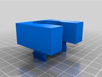
The weight consists of two separate and displaceable parts: the outer shell and the inner assembly-block (frame, motor, batteries, coin-weight, etc). The position of the free-moving outer shell relative to the assembly-block depends on whether the weight hangs at the uppermost position or at the lowest position on the chain. To detect this, a bi-stable switching mechanism is provided which switches the electric motor. If the weight is completely down, the chain will tension the outer shell up relative to the inner assembly and this actuates the switch what starts the motor. As a result, the weight begins to climb on the chain up until it reaches the bottom of the clock. The clock pushes the outer shell down relative to the assembly and the switch stops the motor. And the game starts again, the weight sinks with the chain until it reaches the lowest position then the weight climbs back to the top on the chain... It's so simple... written... but let's see...
The climbing weight
The weight includes a tiny cheap and easily available (Ebay / AliExpress / Amazon) geared electric motor. The energy for the movement is provided by 4 pieces 1.5 Volt batteries connected in series. The mass of the weight can be further increased with coins. The current version is designed to fit 21.3 mm diameter coins. So, the 5 Euro cents, the 5 USD cents or the 5 HUF fit perfectly. It can also be used with smaller diameter coins, but care must be taken to ensure that the ball chain does not reach the coins. The mass can be any other thing, putting them into a small plastic bag and placing it into the coin compartment. I put 2x15 pieces of 5 HUF in it, so the total mass of the weight is 320 grams. Actually, my clock runs at 200 grams too, I tried it, but it depends a lot on how heavy and long (inertia and forces) the pendulum is and how much friction there is in the clock’s mechanics (but YMMV). You can experiment ... I use a micro switch desoldered from a defect mouse, but this kind of switch is also easy to get from the online stores. I made the contacts of the battery holder from a ball point pen spring and drawing pins. The two shafts of the pulleys can be made from a suitable nail. The rod of the switch actuating mechanism can be a 3 mm diameter wood stick, or a rod can be printed out with the associated switch actuator. The whole mechanism is covered with a cylindrical shell, two halves of which adhere to each other with small magnets. This makes it very easy to disassemble and control the climbing weight. Instead of magnet, four pieces shafts placed into the hole of magnets as pin bolts are also suitable...
The clockThe base of the clock I built earlier is designed by A26 (https://www.thingiverse.com/thing:1739676, One Plate Mechanical Clock) Credit to him for this. It is a nice minimal design clock, it shows the basic components needed to operate a clock, easy to print then assemble. I especially like this clock that the clock-face can be replaced with another look as you like, no need to disassemble/change/assemble the clock. I wanted to keep it itself as original as possible so that the gears / parts could still be seen during operation. https://www.thingiverse.com/make:929621 Remix issue Thingiverse: https://www.thingiverse.com/groups/thingiverse/forums/site-issues-and-feedback/topic:48410
Changes and remarks on the clock
The only change that is absolutely necessary to be able to operate the clock with a chain instead of a rope is described at the point 1. The rests are only needed because of the reliability or circumstances, e.g. I do not have any penny. The changes I made to the pendulum clock are as follows:
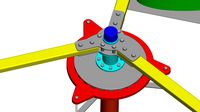
1 The winding drum (drumb.stl -> CW_CLOCK_drumb.stl) has been redesigned so that the weight hangs on a ball chain instead of a cord.2 A hole has been made throught the ratchet part of the drum (druma.stl -> CW_CLOCK_druma.stl) for a screw (=cotter pin) so that the ratchet cannot rotate on the shaft. Accordingly, an about 4mm wide flat part 27mm from the end was made on the 75 mm long shaft. This provides a more reliable force transmission than the grip and/or glue between the shaft and the ratchet.3 A "top point stopper" (CW_CLOCK_stopper.stl) has been created so that the weight does not collide with the dial plate or the clock escapement when it climbs up. The stopper simply snaps onto the frame of the clock.4 I cut a thread on both ends of the pendulum's rod, so I can easily fine-tune the balance of the pendulum and the time keeping accuracy of the clock. I also resized the coin holders of the pendulum (bobs, penweight.stl) to fit 100 HUF. One coin is placed at each end. To Hungarians: I didn't know it before, but with the same look, this coin exists in two different weights.5 Added a washer under the escapement wheel to avoid any collision between the wheel and the frame.6 Pendulum bar (200 mm shaft) fixation improved, drilled a hole and added a security screw to the anchor.7 I printed the "-v2" variant for wheel4 assembly. It requires an additional Ø3x16mm shaft but allows easier hour-hand adjustments in the daily use of the clock. Just medium grip needs between the shaft and the wheels.8 I also modified the bearing nests on the frame because I had bearings of other sizes (11x5x5mm) at home. This stl is not included.
In order for the climbing weight to be used for other clocks, a ball chain gear of the appropriate size must be attached / mounted to the winding drum of the clock. The higher the number of teeth on the chain gear, the lower the weight required to drive the clock. A little help making the proper ball chain gear can be found here: https://www.thingiverse.com/thing:4851360
The continuous operation requires an endless ball chain. For this, I printed a simple “cavity” tool (CW_TOOL_ball_chain_cavity.stl) so that the chain can be looped with a traditional combination pliers. Print two pieces...
Recommended assembly method and adjustment:
Coming soon...after request
Bom (non-printable components):
• 1 pc geared electric motor, GA12-N20, 6V, 30rpm
https://www.aliexpress.com/item/33022320164.html
• 1 pc switch, D2FC-F-7N
https://www.aliexpress.com/item/32924769791.html
• 1-3 m ball (bead) chain, Ø3.2 mm, ≈225 ball/meter (can be colored e.g. brass)
https://www.aliexpress.com/item/4001148205301.html
• 1 pc screw and nut, M3, min. 18 mm
https://www.aliexpress.com/item/10000181324125.html
• 2 pcs shafts Ø3x21 mm
https://www.aliexpress.com/item/32297671032.html
• 8 pcs magnets Ø3x6 mm (or 4 shafts Ø3x10-12 mmm)
https://www.aliexpress.com/item/1005001515842121.html
• 1 pc flyback (snubber) diode to protect the switch. 1N400X or 1N4148, etc.
• 4 pcs AA battery, 1.5V
• 2 pcs ballpoint pen spring
• 2 pcs flat head metal push pin
• 15 cm wire
• lots of coin
• super glue
Postscript
I have had the clock with the self climbing weight for about ten days. My ball chain was 3 meters long, so it hung about a meter and a half from the clock. With this length the weight reached the bottom point approx. every 12 hours and climbed back to the clock. With a shorter chain, the clock-weight would pull itself upThe modification requires only minimal changes to the clock hardware itself, virtually 99% of the original clock remains intact.
With this method, many 3D printed weight-driven clocks can be automated (even after completion) without having to delve deep into the structure of the clock. Plus, it's all completely hidden, no one can recognize that the clock is automatized. more often. I wanted to see frequently how the weight climbs up, so I recently shortened the chain, now it hangs just about 80 cm. I have no idea how long the batteries and mechanics will last, so far I don’t see any problems.
Update 30.04.2021
After roughly 3 weeks of continuous operation, the switch became intermittent because its contacts have burned out. I replaced the switch and soldered a flyback diode to the motor terminals to protect the switch against the inductive voltage spikes. Component added to the bom list. See photo about the installation.
Demo:https://youtu.be/jV5sDiRVjcE
Concept:https://youtu.be/RdRMT0bqkkohttps://youtu.be/s17w4Eyq9Rc
Don’t worry, if you forgot to wind up your clock. The clock itself will do it for you...Abstract
I’ve wanted to make a pendulum clock for a long time, so I printed one recently. However, I seem to be lazy enough to keep this alive continuously and wind it twice a day (once if I would use a pulley bearing as a two-fall compound). That is why I made an automatic winding mechanism but not in the usual way. Instead, I redesigned the clock weight itself. Thus, a "dumb and puffy" hanging-only part became an active component of the mechanism, supporting the operation of the clock :). The modification requires only minimal changes to the clock hardware itself, virtually 99% of the original clock remains intact.With this method, many 3D printed weight-driven clocks can be automated (even after completion) without having to delve deep into the structure of the clock. Plus, it's all completely hidden, no one can recognize that the clock is automatized.
The concept
The energy needed to operate the clock is still provided by the potential energy of a weight. However, the commonly used cord to hang weights is replaced by an endless metal ball chain. The chain is placed on the slightly modified winder drum and the weight "clings" to this chain. Once the weight has reached a certain lower level while the clock is running, it climbs its own to the upper position. The clock can also be wound up manually by pulling the other half of the chain in the usual way to lift the weight again.
The weight consists of two separate and displaceable parts: the outer shell and the inner assembly-block (frame, motor, batteries, coin-weight, etc). The position of the free-moving outer shell relative to the assembly-block depends on whether the weight hangs at the uppermost position or at the lowest position on the chain. To detect this, a bi-stable switching mechanism is provided which switches the electric motor. If the weight is completely down, the chain will tension the outer shell up relative to the inner assembly and this actuates the switch what starts the motor. As a result, the weight begins to climb on the chain up until it reaches the bottom of the clock. The clock pushes the outer shell down relative to the assembly and the switch stops the motor. And the game starts again, the weight sinks with the chain until it reaches the lowest position then the weight climbs back to the top on the chain... It's so simple... written... but let's see...
The climbing weight
The weight includes a tiny cheap and easily available (Ebay / AliExpress / Amazon) geared electric motor. The energy for the movement is provided by 4 pieces 1.5 Volt batteries connected in series. The mass of the weight can be further increased with coins. The current version is designed to fit 21.3 mm diameter coins. So, the 5 Euro cents, the 5 USD cents or the 5 HUF fit perfectly. It can also be used with smaller diameter coins, but care must be taken to ensure that the ball chain does not reach the coins. The mass can be any other thing, putting them into a small plastic bag and placing it into the coin compartment. I put 2x15 pieces of 5 HUF in it, so the total mass of the weight is 320 grams. Actually, my clock runs at 200 grams too, I tried it, but it depends a lot on how heavy and long (inertia and forces) the pendulum is and how much friction there is in the clock’s mechanics (but YMMV). You can experiment ... I use a micro switch desoldered from a defect mouse, but this kind of switch is also easy to get from the online stores. I made the contacts of the battery holder from a ball point pen spring and drawing pins. The two shafts of the pulleys can be made from a suitable nail. The rod of the switch actuating mechanism can be a 3 mm diameter wood stick, or a rod can be printed out with the associated switch actuator. The whole mechanism is covered with a cylindrical shell, two halves of which adhere to each other with small magnets. This makes it very easy to disassemble and control the climbing weight. Instead of magnet, four pieces shafts placed into the hole of magnets as pin bolts are also suitable...
The clockThe base of the clock I built earlier is designed by A26 (https://www.thingiverse.com/thing:1739676, One Plate Mechanical Clock) Credit to him for this. It is a nice minimal design clock, it shows the basic components needed to operate a clock, easy to print then assemble. I especially like this clock that the clock-face can be replaced with another look as you like, no need to disassemble/change/assemble the clock. I wanted to keep it itself as original as possible so that the gears / parts could still be seen during operation. https://www.thingiverse.com/make:929621 Remix issue Thingiverse: https://www.thingiverse.com/groups/thingiverse/forums/site-issues-and-feedback/topic:48410
Changes and remarks on the clock
The only change that is absolutely necessary to be able to operate the clock with a chain instead of a rope is described at the point 1. The rests are only needed because of the reliability or circumstances, e.g. I do not have any penny. The changes I made to the pendulum clock are as follows:
1 The winding drum (drumb.stl -> CW_CLOCK_drumb.stl) has been redesigned so that the weight hangs on a ball chain instead of a cord.2 A hole has been made throught the ratchet part of the drum (druma.stl -> CW_CLOCK_druma.stl) for a screw (=cotter pin) so that the ratchet cannot rotate on the shaft. Accordingly, an about 4mm wide flat part 27mm from the end was made on the 75 mm long shaft. This provides a more reliable force transmission than the grip and/or glue between the shaft and the ratchet.3 A "top point stopper" (CW_CLOCK_stopper.stl) has been created so that the weight does not collide with the dial plate or the clock escapement when it climbs up. The stopper simply snaps onto the frame of the clock.4 I cut a thread on both ends of the pendulum's rod, so I can easily fine-tune the balance of the pendulum and the time keeping accuracy of the clock. I also resized the coin holders of the pendulum (bobs, penweight.stl) to fit 100 HUF. One coin is placed at each end. To Hungarians: I didn't know it before, but with the same look, this coin exists in two different weights.5 Added a washer under the escapement wheel to avoid any collision between the wheel and the frame.6 Pendulum bar (200 mm shaft) fixation improved, drilled a hole and added a security screw to the anchor.7 I printed the "-v2" variant for wheel4 assembly. It requires an additional Ø3x16mm shaft but allows easier hour-hand adjustments in the daily use of the clock. Just medium grip needs between the shaft and the wheels.8 I also modified the bearing nests on the frame because I had bearings of other sizes (11x5x5mm) at home. This stl is not included.
In order for the climbing weight to be used for other clocks, a ball chain gear of the appropriate size must be attached / mounted to the winding drum of the clock. The higher the number of teeth on the chain gear, the lower the weight required to drive the clock. A little help making the proper ball chain gear can be found here: https://www.thingiverse.com/thing:4851360
The continuous operation requires an endless ball chain. For this, I printed a simple “cavity” tool (CW_TOOL_ball_chain_cavity.stl) so that the chain can be looped with a traditional combination pliers. Print two pieces...
Recommended assembly method and adjustment:
Coming soon...after request
Bom (non-printable components):
• 1 pc geared electric motor, GA12-N20, 6V, 30rpm
https://www.aliexpress.com/item/33022320164.html
• 1 pc switch, D2FC-F-7N
https://www.aliexpress.com/item/32924769791.html
• 1-3 m ball (bead) chain, Ø3.2 mm, ≈225 ball/meter (can be colored e.g. brass)
https://www.aliexpress.com/item/4001148205301.html
• 1 pc screw and nut, M3, min. 18 mm
https://www.aliexpress.com/item/10000181324125.html
• 2 pcs shafts Ø3x21 mm
https://www.aliexpress.com/item/32297671032.html
• 8 pcs magnets Ø3x6 mm (or 4 shafts Ø3x10-12 mmm)
https://www.aliexpress.com/item/1005001515842121.html
• 1 pc flyback (snubber) diode to protect the switch. 1N400X or 1N4148, etc.
• 4 pcs AA battery, 1.5V
• 2 pcs ballpoint pen spring
• 2 pcs flat head metal push pin
• 15 cm wire
• lots of coin
• super glue
Postscript
I have had the clock with the self climbing weight for about ten days. My ball chain was 3 meters long, so it hung about a meter and a half from the clock. With this length the weight reached the bottom point approx. every 12 hours and climbed back to the clock. With a shorter chain, the clock-weight would pull itself upThe modification requires only minimal changes to the clock hardware itself, virtually 99% of the original clock remains intact.
With this method, many 3D printed weight-driven clocks can be automated (even after completion) without having to delve deep into the structure of the clock. Plus, it's all completely hidden, no one can recognize that the clock is automatized. more often. I wanted to see frequently how the weight climbs up, so I recently shortened the chain, now it hangs just about 80 cm. I have no idea how long the batteries and mechanics will last, so far I don’t see any problems.
Update 30.04.2021
After roughly 3 weeks of continuous operation, the switch became intermittent because its contacts have burned out. I replaced the switch and soldered a flyback diode to the motor terminals to protect the switch against the inductive voltage spikes. Component added to the bom list. See photo about the installation.
Similar models
thingiverse
free

Ball-Chain Pulley and Penny Pendulum Zip-tie Clips for Polargraph by DocJames
...p ties. this is a simple replacement for "weight for swinging pendulum" by bre (http://www.thingiverse.com/thing:17016)
thingiverse
free

Flower clock by arifg
...ck-movement-for-mechanism-repair-diy-parts-clock-parts-accessories-pendulum/32602619548.html?spm=a2g0s.9042311.0.0.30864c4dnjcv5f
thingiverse
free

Pendulum by ThingiJay
...ic pendulum i made to replace one on a battery operated clock i have. it was decorative and so didn't need any weight to it.
thingiverse
free

Pendulum Wall Clock Final v2 by lustertone
... smoothly. i also added a tiny bit more to the hour/minute/seconds gear shafts so they would not have much friction between them.
thingiverse
free

Printed Pendulum + "Improved" Coinholders + back plate for A26 's One Plate Clock by NODONTTOUCHTHAT
...usted more easily and doesn't let coins fall out. holds coins up to 26mm in diameter. the backplate requires one m3*10 screw.
thingiverse
free
Pendulum by aviyahalom
...ng gears but the were too rigid and prevented the mechanism from turning.
you can view a video here: https://youtu.be/tlrrfoftqls
grabcad
free

Wooden Pendulum Clock- Mechanical Wooden Clock
...tting, and others need basic craftsmanship. besides, my next step is develop this model and draw a suitable clock cabinet for it.
thingiverse
free

Winding key for clock pendulum by loumgg
...ng key for clock pendulum, for 3,3 mm square
clef de remontage pour horloge pendule mécanique, pour un carré de pendule de 3,3 mm
thingiverse
free

waterjet clock rev 4 by engunneer
...ront gear on the right shaft is connected to the ratchet and pawl mechanism and can be used for winding the weight back up again.
thingiverse
free

Fidget Cube Replica by dudu_abdu
...; (and remember to locate the sixth tactile switch and the steel ball bearing inside the 'ball holder" before gluing it)
Krahut
thingiverse
free

Ball (bead) chain gears by krahut
...ballchain.com/chain-sizes/
click like if you find a good one or write a comment if you feel there would be something to change...
thingiverse
free

Z axis level indicator gauge (Dual Z axis stepper alignmen / synchronization check) by krahut
... also leads to faulty bed leveling.
some videos for better understanding:https://youtu.be/8k2pwq4to8shttps://youtu.be/dbp7phog7x0
Pendulum
turbosquid
$10

Pendulum
... available on turbo squid, the world's leading provider of digital 3d models for visualization, films, television, and games.
turbosquid
$5

pendulum
... available on turbo squid, the world's leading provider of digital 3d models for visualization, films, television, and games.
3d_export
$5

pendulum of newton
...pendulum of newton
3dexport
newton's pendulum is made with respect to proportions and dimensions.
turbosquid
$20

pendulum clock
...uid
royalty free 3d model pendulum clock for download as c4d on turbosquid: 3d models for games, architecture, videos. (1489452)
turbosquid
$19

Pendulum trainer
...3d model pendulum trainer for download as , fbx, stl, and obj on turbosquid: 3d models for games, architecture, videos. (1684795)
turbosquid
$10

Foucault pendulum
...odel foucault pendulum for download as 3ds, max, obj, and fbx on turbosquid: 3d models for games, architecture, videos. (1441097)
turbosquid
$5

pendulum clock
... available on turbo squid, the world's leading provider of digital 3d models for visualization, films, television, and games.
design_connected
free

Pendulum Wall Mirror
...pendulum wall mirror
designconnected
free 3d model of pendulum wall mirror by cb2 designed by mermelada estudio.
3d_export
$65

big pendulum
...big pendulum
3dexport
simple rendering of the scene file
3d_ocean
$15

Pendulum Clock Kit
...endulum clock kit with a real clock system inside that you can control. the kit/rig is fully functional and controlled by xpresso
Climbing
3d_ocean
$9

Climbing Axe
...dy to be put into action. fits perfect for fps / third person games. low poly (1019 polygons – 856 vertices) 4096×4096 png tex...
turbosquid
$6

Inflatable Climbing
...d
royalty free 3d model inflatable climbing for download as on turbosquid: 3d models for games, architecture, videos. (1298328)
turbosquid
$19

Combination for climbing
...el combination for climbing for download as max, obj, and fbx on turbosquid: 3d models for games, architecture, videos. (1601482)
3d_ocean
$12

Tall Climbing Plant
...d fbx flower green interior max mentalray obj plant pot round tall vray white
3d model of tall climbing plant in white round pot.
turbosquid
$60

wall climbing
... available on turbo squid, the world's leading provider of digital 3d models for visualization, films, television, and games.
turbosquid
$45

Climbing Shoe
... available on turbo squid, the world's leading provider of digital 3d models for visualization, films, television, and games.
turbosquid
$32

Atomi Climb
... available on turbo squid, the world's leading provider of digital 3d models for visualization, films, television, and games.
turbosquid
$30

Set For Climbing
... available on turbo squid, the world's leading provider of digital 3d models for visualization, films, television, and games.
turbosquid
$20

Tower for Climbing
... available on turbo squid, the world's leading provider of digital 3d models for visualization, films, television, and games.
turbosquid
$20

Set for Climbing
... available on turbo squid, the world's leading provider of digital 3d models for visualization, films, television, and games.
Driven
turbosquid
$50
CHAIN DRIVEN CONVEYOR
... available on turbo squid, the world's leading provider of digital 3d models for visualization, films, television, and games.
3d_export
free
driven shaft of the lump crusher
...driven shaft of the lump crusher
3dexport
3d_export
$27
n95 full servo driven mask printer
...n95 full servo driven mask printer
3dexport
n95 full servo driven mask printer
turbosquid
$16
(Project) Food packing helper machine with holding clamp and press table driven by an actuator
... available on turbo squid, the world's leading provider of digital 3d models for visualization, films, television, and games.
3d_export
$47
the fifth generation of one driven two new mask machine
...ing, lamination, pressing, ear band tapping, ultrasonic, etc. the structure of the model is detailed, including model parameters.
3d_export
$15
industrial belt-driven air cooler
...leaning up necessary, just drop your models into the scene and start rendering/texturing. no special plugin needed to open scene.
3d_export
free

golf cart
...golf cart 3dexport golf cart for golfers to be driven in...
3d_export
$10
design and assembly of pulley
...pulley 3d model which is used for drive and driven ...
archive3d
free
Windmill 3D Model
...windmill 3d model archive3d wind turbine wind-driven powerplant wind-electric set windmill n181208 - 3d model (*.gsm+*.3ds)...
3d_export
$30
Compressed Air Engine 3D Model
...motor flywheel shaft camshaft piston valve block engineering compressed-air driven compressed air engine 3d model zenmunster 92451...
Winding
design_connected
$4

Wind
...wind
designconnected
emmemobili wind dining tables computer generated 3d model. designed by chiara vaghi.
3d_ocean
$4

Wind Turbine
...n
and render setup turbine wind
wind turbine, modeled with cinema4d r13 , render setup and textured, custom logo for wind turbine
3d_export
$40
wind turbine
...wind turbine
3dexport
wind turbine
3d_export
$40

wind turbine
...wind turbine
3dexport
wind turbine
3d_export
$40
wind turbine
...wind turbine
3dexport
wind turbine
3d_export
$40
wind turbine
...wind turbine
3dexport
wind turbine
3d_export
$40
wind turbine
...wind turbine
3dexport
wind turbine
3d_export
$40
wind turbine
...wind turbine
3dexport
wind turbine
3d_export
$40

wind turbine
...wind turbine
3dexport
wind turbine
3d_export
$40
wind turbine
...wind turbine
3dexport
wind turbine
Clock
3d_ocean
$4

Clock
...clock
3docean
clock hand kitchen clock time watch
a clock
archibase_planet
free

Clock
...clock
archibase planet
clock table clock alarm-clock
clock orange - 3d model (*.gsm+*.3ds) for interior 3d visualization.
archibase_planet
free

Clock
...clock
archibase planet
clock table clock alarm-clock
clock yellow - 3d model (*.gsm+*.3ds) for interior 3d visualization.
archibase_planet
free
Clock
...clock
archibase planet
clock alarm-clock
clock n100707 - 3d model for interior 3d visualization.
archibase_planet
free

Clock
...clock
archibase planet
clock table clock
clock - 3d model (*.gsm+*.3ds) for interior 3d visualization.
archibase_planet
free

Clock
...clock
archibase planet
clock striking clock
clock - 3d model (*.gsm+*.3ds) for interior 3d visualization.
archibase_planet
free
Clock
...clock
archibase planet
clock wall clock
clock 1 - 3d model (*.gsm+*.3ds) for interior 3d visualization.
archibase_planet
free
Clock
...clock
archibase planet
clock wall clock
clock 2 - 3d model (*.gsm+*.3ds) for interior 3d visualization.
archibase_planet
free

Clock
...clock
archibase planet
clock wall clock
clock 3 - 3d model (*.gsm+*.3ds) for interior 3d visualization.
archibase_planet
free

Clock
...clock
archibase planet
alarm clock alarm-clock
clock - 3d model (*.gsm+*.3ds) for interior 3d visualization.
Clocks
3d_ocean
$4
Clock
...clock
3docean
clock hand kitchen clock time watch
a clock
archibase_planet
free
Clock
...clock
archibase planet
clock table clock alarm-clock
clock orange - 3d model (*.gsm+*.3ds) for interior 3d visualization.
archibase_planet
free
Clock
...clock
archibase planet
clock table clock alarm-clock
clock yellow - 3d model (*.gsm+*.3ds) for interior 3d visualization.
archibase_planet
free
Clock
...clock
archibase planet
clock alarm-clock
clock n100707 - 3d model for interior 3d visualization.
archibase_planet
free
Clock
...clock
archibase planet
clock table clock
clock - 3d model (*.gsm+*.3ds) for interior 3d visualization.
archibase_planet
free
Clock
...clock
archibase planet
clock striking clock
clock - 3d model (*.gsm+*.3ds) for interior 3d visualization.
archibase_planet
free
Clock
...clock
archibase planet
clock wall clock
clock 1 - 3d model (*.gsm+*.3ds) for interior 3d visualization.
archibase_planet
free
Clock
...clock
archibase planet
clock wall clock
clock 2 - 3d model (*.gsm+*.3ds) for interior 3d visualization.
archibase_planet
free
Clock
...clock
archibase planet
clock wall clock
clock 3 - 3d model (*.gsm+*.3ds) for interior 3d visualization.
archibase_planet
free
Clock
...clock
archibase planet
alarm clock alarm-clock
clock - 3d model (*.gsm+*.3ds) for interior 3d visualization.
Self
3ddd
$1

Self
... банкетка
каталог minotti 2010модель selfдизайнер rodolfo dordoniш\д\в 60\120\42
3ddd
$1

Minotti Self
...minotti self
3ddd
minotti
банкетка minotti self
3ddd
$1
Minotti Self
...minotti self
3ddd
minotti , self
текстуры и материалы прилагаются.
3ddd
$1

Self cleaning ashtrays
...self cleaning ashtrays
3ddd
пепельница
self cleaning ashtrays
turbosquid
$15

Book self
...
royalty free 3d model book self for download as max and fbx on turbosquid: 3d models for games, architecture, videos. (1502520)
3d_export
free
self-tapping screw
...self-tapping screw
3dexport
self-tapping screw 55 мм
turbosquid
$12

Book Self
...lty free 3d model book self for download as max, obj, and fbx on turbosquid: 3d models for games, architecture, videos. (1473695)
turbosquid
$4

Self with Desk
...d model self with desk for download as 3ds, max, obj, and fbx on turbosquid: 3d models for games, architecture, videos. (1511139)
turbosquid
$2

Book Self
...ree 3d model book self for download as max, fbx, 3ds, and obj on turbosquid: 3d models for games, architecture, videos. (1544366)
turbosquid
$2

Book self
...ree 3d model book self for download as 3ds, max, fbx, and dwg on turbosquid: 3d models for games, architecture, videos. (1300384)
Weight
archibase_planet
free

Weight
...weight
archibase planet
weight
weight n030907 - 3d model for interior 3d visualization.
3ddd
$1
Weighted
...weighted
3ddd
weighted
высота (см)165ширина (см)75
archibase_planet
free

Weight
...weight
archibase planet
weight dumb-bell dumbbell
weight 24 kg n290313 - 3d model (*.gsm+*.3ds) for interior 3d visualization.
3d_export
free
weight
...weight
3dexport
archibase_planet
free

Weight
...weight
archibase planet
gym sport equipments
sport`s weight n010907- 3d model for interior 3d visualization.
turbosquid
$14

Weight
...uid
royalty free 3d model weight for download as max and obj on turbosquid: 3d models for games, architecture, videos. (1197215)
turbosquid
$19

Weight
...alty free 3d model weight for download as , stl, obj, and fbx on turbosquid: 3d models for games, architecture, videos. (1684982)
turbosquid
$4
Weights
...yalty free 3d model weights for download as max, obj, and fbx on turbosquid: 3d models for games, architecture, videos. (1494762)
turbosquid
$6
weights
... free 3d model weights for download as 3ds, obj, c4d, and fbx on turbosquid: 3d models for games, architecture, videos. (1261435)
turbosquid
$3

weight
...free 3d model weight for download as blend, dae, fbx, and obj on turbosquid: 3d models for games, architecture, videos. (1558127)