Thingiverse
Sega Master System 2 NoCut AV Mod by tempura
by Thingiverse
Last crawled date: 2 years, 10 months ago
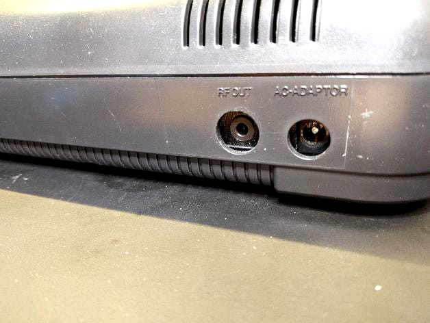
This mod brings out the Composite (not the RGB as in the original mod, so the image quality might not be as good as with the other mod) video signal and the audio signal (mono only) to a 4-pole headphone jack.
Double check everything before powering up. I am not to be held responsible in any way if you screw up your precious console!
I liked the idea of the original mod (thans @zitruskeks for sharing!), but as no sources were given and I had no suitable connectors at hand, I re-designed this in OpenSCAD to be able to fit a 4-pole 3.5mm headphone jack. I had some cables lying around from older cell phones which usually provided a composite signal from the jack via the 4th ring.
As stated in the original Thing, you will need to de-solder the RF modulator (no modern TV I know of still sports an analogue TV capable receiver anyway) in order to put this into place. The thermal mass of the shielding is rather high, so be careful on removal.
Note: I helped myself with a trick I picked up recently: adding a little bit of Bismuth (https://en.wikipedia.org/wiki/Bismuth#Other_metal_uses_and_specialty_alloys, you can get this easily e.g. on Amazon) to the solder. This will drop the melting point significantly and using a solder sucker becomes much more easy as the solder takes more time to solidify. Just be sure to thoroughly clean off the remaining solder once you are done.
I got the jacks from here: https://www.amazon.com/s?k=B089222S84 and with the current design they fit nicely flush. Just attach the cable you want to use and use a Multimeter to check which tab goes to which part of the cable.
For the other connections I did some research on the net (the key word is CXA1145P, which is the signal encoder used in the SMS2) and what I found working nicely is to
put 75Ohms (I used 2x 150Ohms in parallel) in series with a 220uF electrolytic capacitor for the Composite video signal
put a 10uF electrolytic capacitor in series for the audio signal
To get the best signal quality possible, I grabbed them immediately after the chip. According to the SMS2 schematic (I love the Internet), I had to remove some components to avoid interference ('upper' means near to the backside):
de-solder R21, R28, C40 from the board
use the 'upper' solder pad of R21 for the video signal
use the 'upper' solder pad of R28 for the mono audio signal (just split it after the cap)
Please check the pictures for details. I also used two grounding points just to be safe.
Note: for the electrolytics, I put the positive side next to the CXA1145P pins. Don't know how much difference it makes, though.
The print should fit snugly between the power supply connector and the RF shielding.
If you happen to have other jacks, just go ahead and check the OpenSCAD source how to modify it according to your needs.
Finally: Have fun playing the old classics!
Similar models
thingiverse
free

VTech Socrates Composite Mod RF Box Replacement
...), second (ground) and third (video) wires. this box will then sit in the same area as the rf box and allow 3 jacks to be added.
cg_trader
$2

AUX Cable - headphone jack
...udio jack, headphone jack or jack plug, is a family of electrical connectors typically used for analog audio signals. (wikipedia)
thingiverse
free

replacement jack analog stereo by ryks
...int this stereo case and utilise the audio iron jack to put in ,solder new cables and mont it .
be free to modify and spread on .
thingiverse
free

Atari 7800 Composite Mod Mount by the16bitgamer
...f module was.
melt the legs so the mod wont fall out
finish the mod
put the rf shield back on. you might need to bend the leads.
thingiverse
free

Headphone Clip for Windows Mixed Reality - LENOVO add on by Roadrunner06
...n pla materials, 205 degree nozzle, 0.2mm layer height supports as required, just try to positioned it properly to reduce support
thingiverse
free

Audio jack plug by jason_atwood
...erhaps under your desk. this thing will hold the female end of a audio cable and allow you to just plug your headphones right in.
thingiverse
free

3.5mm Headphone Jack Desk Holder
...t one of these cables (it's what i had on hand): https://www.amazon.com/amazonbasics-3-5mm-female-stereo-audio/dp/b01cnauyby/
thingiverse
free

Superlux HD-681 audio-jack adapter
...the plug
for the proper wiring, use this helpful thread: https://www.head-fi.org/threads/need-help-wiring-superlux-hd668b.877749/
thingiverse
free

Gameboy Classic DMG Headphone Jack Bracket / Mount by WillowLazuli
...widely available.
printing:
i printed this on an anycubic photon at 0.05 layer height at a 15 degree angle and light supports.
thingiverse
free

Dual Jack cable holder by zeroq
...ables.
there are two holes used for an audio cable extender and also a central hole for other extra cables.
designed with blender
Nocut
thingiverse
free

Hi-Def NES No Cut Mod by collingall
...several pieces that need to be printed. hi-def nes nocut mid section.stl hi-def nes nocut board mount.stl hi-def nes...
cg_trader
$30

Storm Punk | 3D
...2 heads variant 30cm and 20 cm ,cut and nocut xmen storm marvel figure magneto wolverine stormpunk superhero comic...
Tempura
3ddd
$1

Hosomaki Tempura fish
...hosomaki tempura fish
3ddd
ролл
this is a salmon tempura hosomaki sushi
turbosquid
$5

Hosomaki tempura fish sushi
... available on turbo squid, the world's leading provider of digital 3d models for visualization, films, television, and games.
3d_sky
$8

Hosomaki Tempura fish
...hosomaki tempura fish
3dsky
sushi
this is a salmon tempura hosomaki sushi
thingiverse
free

Improved New 3DS charger dock door by tempura
...lly pull the cable back and align the door with the base.
fasten the screw and enjoy.
thanks @dash_lambda for sharing his design!
thingiverse
free

gloogun
...potato digging class and harvest food. the food includes tempura bread and more. at 11 am, jun gathers in...
cg_trader
$12

Tempura
...tempura
cg trader
tempura 3d model.
cg_trader
$10

Squid Tempura
...quid tempura
cg trader
3d squid tempura other squid seafood, formats max, obj, 3ds, fbx, stl, dwg, ready for 3d animation and ot
cg_trader
$8

Prawn Tempuras
...n tempuras
cg trader
prawn tempuras 3d cuisine food, formats include max, obj, 3ds, fbx, stl, dae, ready for 3d animation and ot
cg_trader
$10

Hosomaki Tempura fish sushi
...hosomaki tempura fish sushi
cg trader
this is a tempura hosomaki sushi with salmon, tilapia, avocado and microgreens
Sega
turbosquid
$5

Sega Dreamcast
... available on turbo squid, the world's leading provider of digital 3d models for visualization, films, television, and games.
cg_studio
$79

Sega Megadrive3d model
...sega megadrive3d model
cgstudio
.max - sega megadrive 3d model, royalty free license available, instant download after purchase.
cg_studio
$79

Sega Saturn3d model
...sega saturn3d model
cgstudio
.max - sega saturn 3d model, royalty free license available, instant download after purchase.
cg_studio
$43

Sega Dreamcast3d model
...sega dreamcast3d model
cgstudio
.max - sega dreamcast 3d model, royalty free license available, instant download after purchase.
3ddd
$1

Sega Mega Drive 16-bit
...sega mega drive 16-bit
3ddd
sega , игровая приставка
sega mega drive 16-bit
3d_export
$79

Sega Saturn 3D Model
...vintage old retro photorealistic toy computer people play nostalgia classic cartridge
sega saturn 3d model fabelar 29760 3dexport
3d_export
$79

Sega Megadrive 3D Model
...tage old retro photorealistic toy computer people play nostalgia classic cartridge
sega megadrive 3d model fabelar 29423 3dexport
3d_export
$47

Sega Dreamcast 3D Model
...alistic toy computer people play nostalgia classic cartridge gaming video game pal
sega dreamcast 3d model fabelar 62969 3dexport
cg_studio
$79

Sega Master System3d model
... nostalgia classic cartridge
.max - sega master system 3d model, royalty free license available, instant download after purchase.
3d_export
$10

Sega game console
...sega game console
3dexport
rar arhive 3dmax2019 fbx obj material texture
Av
3ddd
$1

AV Mazzega
...orolla , av mazzega
светильника: av mazzega, модель: corolla
ширина: 49 см
высота: 25 см
3ddd
$1

бра AV MAZZEGA
...бра av mazzega
3ddd
av mazzega
бра av mazzega из коллекции
curiosity cabinet
3d_export
free

avs model 6
...avs model 6
3dexport
avs model 6
3ddd
$1

светильник AV Mazzega
...светильник av mazzega
3ddd
avmazzega
светильник av mazzega (подвесной)
turbosquid
$49

AVE Milano
...bosquid
royalty free 3d model ave milano for download as max on turbosquid: 3d models for games, architecture, videos. (1503974)
3ddd
$1

AV MAZZEGA Dixie
...av mazzega dixie
3ddd
av mazzega
потолочный светильник dixie из коллекции av mazzega 2013 года
высота - 68см.
диаметр - 46см.
3ddd
$1

Av-Bistrot 3
...v-bistrot , подстолье
классическое подстолье av-bistrot 3. max2012, fbx, obj в комплекте
3ddd
$1

Brilux Aves 100
...brilux aves 100
3ddd
бра. brilux aves 100. польша. материалы настроены.
3ddd
free

Teuco Aveness F04
..., угловая , ванна
teuco aveness f04, 150x150 см
3ddd
$1

Av Mazzega 900
...v mazzega 900
3ddd
av mazzega , муранское стекло
итальянская люстра из муранского стекла
Master
3ddd
$1

Master
...master
3ddd
besana , master
фабрика: besana
master
размер: 80х60х80
design_connected
$20

Masters
...photo-realistic 3d models of the kartell masters chair by philippe starck for 3d architectural and interior design presentations.
3ddd
$1

Masters
...ка на производительяhttp://www.designboom.com/design/philippe-starck-masters-chair-for-kartell-at-milan-design-week-09/
3d_export
$5

master roshi
...master roshi
3dexport
master roshi 3d model good quality for animation
design_connected
$18

Masters Stool
...masters stool
designconnected
kartell masters stool computer generated 3d model. designed by starck, philippe.
3ddd
free

Key Master
...key master
3ddd
игровой автомат , key master
д 950 / ш 950 / в 1850
3ddd
$1

Стул: Masters Chair
... kartell
стул: masters chair
коллекция: masters
бренд: kartell
страна: италия
размеры, см: 83x54x54; высота сиденья – 47.
3d_export
$5

master bedroom
...master bedroom
3dexport
zhu design<br>a modern tropical inspired master bedroom for your model
3ddd
$1

kartel masters
...el masters
3ddd
kartel , masters
в архиве присутствует fbx и модель в 2011 версии макса.
turbosquid
$150

Master Bedroom
...osquid
royalty free 3d model master bedroom for download as on turbosquid: 3d models for games, architecture, videos. (1329485)
Mod
design_connected
$13
MOD. 4233 - MOD. 4234 Table Lamp
...mod. 4233 - mod. 4234 table lamp
designconnected
arcahorn mod. 4233 - mod. 4234 table lamp computer generated 3d model.
design_connected
$11
MOD.1095
...mod.1095
designconnected
mod.1095 computer generated 3d model. designed by sarfatti, gino.
3ddd
$1
fireplaces mod Spec
...fireplaces mod spec
3ddd
камин
fireplaces mod spec 180x90x125h
3ddd
free
Flos Mod. 2129
... mod
фабрика: flos
модель: mod. 2129
описание: подвесной светильник, металл, белый, черный.
сайт: www.flos.com
turbosquid
$34
Mod Lamp.c4d
... available on turbo squid, the world's leading provider of digital 3d models for visualization, films, television, and games.
turbosquid
$32
MOD A 001
... available on turbo squid, the world's leading provider of digital 3d models for visualization, films, television, and games.
turbosquid
$29
Maars Mod
... available on turbo squid, the world's leading provider of digital 3d models for visualization, films, television, and games.
turbosquid
$15
Mod 70..
... available on turbo squid, the world's leading provider of digital 3d models for visualization, films, television, and games.
turbosquid
$10
MOD Sofa
... available on turbo squid, the world's leading provider of digital 3d models for visualization, films, television, and games.
turbosquid
$1
Mod-Lite
... available on turbo squid, the world's leading provider of digital 3d models for visualization, films, television, and games.
System
archibase_planet
free
System
...m
archibase planet
fire alarm system fire alarm box
security light system - 3d model (*.gsm+*.3ds) for interior 3d visualization.
archibase_planet
free
Spider system
...stem spider glass system
spider system to fix glass stefano galli n050912 - 3d model (*.gsm+*.3ds) for interior 3d visualization.
3ddd
$1
Euforia System
...euforia system
3ddd
euforia
euforia system
3d_export
$50
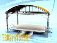
Roof system Truss system 3D Model
...oof system truss system 3d model
3dexport
roof system truss truss stage
roof system truss system 3d model aleksbel 38970 3dexport
3ddd
$1
DVD System
...dvd system
3ddd
dvd , schneider
dvd system
design_connected
free
Seating system
...seating system
designconnected
free 3d model of seating system
3d_export
$5

solar system
...solar system
3dexport
solar system in c4d, with 8k nasa textures
3ddd
$1
Quanta System
...quanta system
3ddd
медицина
quanta system.
лазерное оборудование для медицинских центров
3d_export
$15
solar system
...nd the other the sun, the earth and the moon, the latter has an animation with camera movement included, the files are in spanish
3d_export
$14

missile system
...missile system
3dexport
2
design_connected
$11
No 2
...no 2
designconnected
sibast no 2 computer generated 3d model. designed by sibast, helge.
turbosquid
$6
Cliff Rock 2-2
...uid
royalty free 3d model cliff rock 2-2 for download as obj on turbosquid: 3d models for games, architecture, videos. (1619161)
turbosquid
$29
Book variation 2 2
...3d model book variation 2 2 for download as max, obj, and fbx on turbosquid: 3d models for games, architecture, videos. (1366868)
turbosquid
$22
Classic baluster (2) (2)
...assic baluster (2) (2) for download as max, obj, fbx, and stl on turbosquid: 3d models for games, architecture, videos. (1483789)
turbosquid
$99

Smilodon 2 Pose 2
... available on turbo squid, the world's leading provider of digital 3d models for visualization, films, television, and games.
turbosquid
$20

Barrel Barricade 2-2
... available on turbo squid, the world's leading provider of digital 3d models for visualization, films, television, and games.
turbosquid
$6
Wall Trophy (2) (2)
... available on turbo squid, the world's leading provider of digital 3d models for visualization, films, television, and games.
turbosquid
free
Tire label 2 of 2
... available on turbo squid, the world's leading provider of digital 3d models for visualization, films, television, and games.
3ddd
$1

Кровать, 2 тумбочки, 2 светильника
...кровать, 2 тумбочки, 2 светильника
3ddd
кровать, 2 тумбочки, 2 светильника
нормальное качество
формат 3ds max
без текстур
3ddd
free

Кровать, 2 тумбочки, 2 светильника
...кровать, 2 тумбочки, 2 светильника
3ddd
кровать, 2 тумбочки, 2 светильника
нормальное качество
формат 3ds max
без текстур