Thingiverse
Sansui AU-717 AU-517 speaker binding post adapters by bloblob
by Thingiverse
Last crawled date: 3 years, 3 months ago
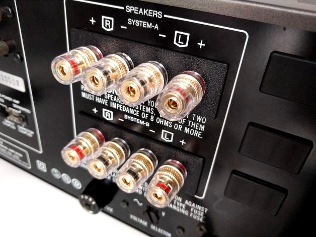
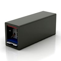
These parts are used to convert a vintage Sansui AU-717 or AU-517 integrated amplifier to use speaker binding posts instead of the original bare wire spring clips. With binding posts you can still use bare stranded wire, but also 4mm banana plugs (recommended), spade terminals, etc.
You will need to buy binding posts (4x red, 4x black) to do this conversion. I used these: https://www.amazon.es/gp/product/B01FQXOYV6, but you may find other compatible options depending on where you live. The binding posts should be the type with a solder tab/ring that detaches from the binding post. This will make it FAR easier to do the soldering, since there isn't much slack in the existing wires.
There is no hardware required to install these, nor drilling/modification of the rear panel. The outer part has a 'key' that locates it in the existing opening. The inner and outer parts are clamped together by the binding posts, and are held firmly (no movement) to the panel.
The inner part has 'partitions' to prevent adjacent wires from touching even if the nut on the binding post came loose. The inner part also has rectangular recesses that keep the solder tabs oriented in specific directions so they won't rotate under strain.
Instructions:
Take pictures of the existing connections before disassembly. It is very important to remember which wire connects to which terminal when assembling later!
Cut the existing wires as close as possible to the terminals of the old speaker clips.
Remove the spring clip terminals. There are spring tabs at either end of each terminal block that must be (very firmly) squeezed together, which will allow them to be pushed out. It might be worth saving these for another project, or to sell on eBay, for example. If it is too much trouble, you can try breaking off the spring tabs at either end.
Strip the wires (18 AWG), leaving about 8mm of bare wire exposed. I started with the lower terminal's wires (labeled System-B on the rear panel). Bend all of the solder tabs to 90 degrees.
The two outer wires (red and yellow in my case) were folded through the eyelets of two of the solder tabs, and soldered. For the two inner wires (black and white), you need to solder the amp wires to the tabs, as well as jumper wires that will connect to the inner tabs of the upper System-A terminal. I found it easier to solder the wires perpendicular to the tabs, from opposite sides (see 3rd photo).
Fit the inner and outer pieces to the lower panel hole, and insert the four binding post threaded shafts (having removed nuts, broken washers, and solder tabs). The outer two are red, the inner two are black. Fit the solder tabs over the shafts, and install the broken washers and nuts loosely. Orient the tabs as shown, and seat them in the rectangular depressions before tightening the nuts. The inner two tabs are turned 90 degrees to allow for the two connections (amp and jumper to upper terminals). It is recommended to use thread locker to prevent the nuts from coming loose, especially if using bare wire or spade terminals.
Repeat the process for the upper terminals.
Similar models
3dwarehouse
free

Binding Post Pair
..., spades, and bare wire. stereo pair in red/black, explodable for a single post. #amp #amplifier #binding_post #speaker #terminal
grabcad
free

Binding post / speaker terminal
...speaker terminal
grabcad
binding post / speaker terminal / banana socket. red version. panel thickness 3 to 5mm. hole size - 8mm
thingiverse
free

Two wire terminal strip by loughkb
...common 6 32 hard disk screws everyone should have plenty of. loop and solder a couple of bare wires for the contact connection.
grabcad
free

Binding Post 4mm Speaker Terminal
...binding post 4mm speaker terminal
grabcad
gold plated panel-mounted audio terminals, banana jack 4mm
thingiverse
free

Kissing the Frog v2.0 Speaker Terminal back plate by ElementRB
...ker terminal form jaycar (au) - https://www.jaycar.com.au/2-way-push-connection-speaker-terminals/p/pt3000
screw holes are all m3
3dwarehouse
free

Keystone Insert, Binding Post, Solder Type, Pair
...6534 and 6535. in this model, 1 foot equals 1 inch (12:1 scale). #audio #binding_post #connectors #keystone #speakers #wall_panel
3dwarehouse
free

Banana Binding Post Round Recessed Speaker Terminal Cup
...banana binding post round recessed speaker terminal cup
3dwarehouse
outer dia - 76.5mm cut hole size dia - 52.5
grabcad
free

Connector; Push Button; 2 Circuit Terminal Block
...ctor; push button; 2 circuit terminal block
grabcad
2-circuit, spring-loaded tab terminal block for speaker wire or prototyping.
grabcad
free

Square Speaker Input Terminal
...square speaker input terminal
grabcad
square speaker input terminal - 2 x screw/binding post
thingiverse
free
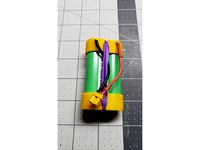
18650 holder 1S / 2S
...make sure they are correctly oriented. 1s instructions follow similar steps as described in the2s construction, however: solder two...
Bloblob


Sansui
thingiverse
free

Sansui G-Series Wood Bonnet Bushing / Grommet / Sleeve by MWH901
...re printed in black resin on an elegoo mars. i cured them for 30 minutes under uv light to improve their hardness and glossiness.
sketchfab
$8

SALE Old Stereo Receiver
...sale old stereo receiver sketchfab sansui 890 stereo receiver 2k pbr textures • albedo •...
grabcad
free

Sansui CD-X211E Compact Disc Player
...on creo, later rendered on keyshot.
see the model in action in the linked video.
let me know what you think!
instagram @jw.pde
cg_trader
free

Sansui 4 way stereo speakers
...ining it a more pleasant dark cherry wood color…. cabinet japanese sansui sp 2000 speakers stereo sturdy wooden electronics audio
cg_trader
$8

Old Stereo Receiver
...old stereo receiver cg trader sansui 890 stereo receiver 2k pbr textures • albedo •...
cg_trader
free

4 way Stereo Speaker dark cherry wood
...in real life, enough. braveheart may have killed my sansui amp, but it couldn't kill these amazing speakers! you...
3dwarehouse
free

Sansui QRX5500 stereo receiver
...sansui qrx5500 stereo receiver
3dwarehouse
specs: oem: sansui year: 1960's/1970's
3dwarehouse
free

Sansui CD-X501 CD player
...sansui cd-x501 cd player
3dwarehouse
specs: oem: sansui year: 1987?
3dwarehouse
free

Sansui CD-V1000 CD player
...sansui cd-v1000 cd player
3dwarehouse
specs: oem: sansui year: 1989
517
turbosquid
$49

S 517 Bus
... available on turbo squid, the world's leading provider of digital 3d models for visualization, films, television, and games.
3ddd
$1

Riva tubular 517
...riva tubular 517
3ddd
riva
фирма riva, текстуры в наличии
3d_export
$60

Architecture 517 3D Model
...lege campus max street landscape commercial building medical hospital offices
architecture 517 3d model lotusmodel 48623 3dexport
3d_export
$160

3d building 517 3D Model
...metropolis street block detailed definition realistic skyscraper huge collection
3d building 517 3d model kanhtart 44556 3dexport
3d_export
$50

3D Home 517 3D Model
... chair furniture texture table lamp apartment rug carpet restaurant hotel sitting
3d home 517 3d model richard3015 46438 3dexport
3d_export
$20

decorative fern in a white flowerpot 517
...e interior in a white pot<br>houseplants<br>exotic plants<br>tropical plants<br>fern<br>nephrolepis
cg_studio
$100

3d building 5173d model
... building 5173d model
cgstudio
.max - 3d building 517 3d model, royalty free license available, instant download after purchase.
3ddd
free

Jeremiah Chandelier
...jeremiah chandelier 3ddd gramercy home цена: 517 у.е. артикул: ch059-5-ir габариты: ширина 155 см глубина 155...
3ddd
$1

Дверь "АРБОЛЕДА" Болеро 21
...дверь "арболеда" болеро 21 3ddd дверь дверь "арболеда" болеро 21http://www.dvkomp.ru/?page=517amp;subcat;=709&id;=1443 800x2100...
3ddd
$1

Belt Elica bl/f/80
...- 798 mm depth - 330 mm height - 517 (950) mm textures included poly count: 14 788...
717
3d_export
$17

Boeing 717-200
...boeing 717-200
3dexport
boeing 717-200
design_connected
$16

Tagliatelle 717
...ted
photo-realistic 3d models of the tagliatelle 717 armchair from alias for 3d architectural and interior design presentations.
3ddd
free

Зеркало 717
...зеркало 717
3ddd
круглое
в fbx файле не наложен turbosmooth на орнаменте .
3d_export
$65

Airliner 717 3D Model
...craft airplane commercial jet airliner civilian flight vehicle transportation
airliner 717 3d model vanishingpoint 73100 3dexport
turbosquid
$10

Corbett Lighting 220-717
...ty free 3d model corbett lighting 220-717 for download as max on turbosquid: 3d models for games, architecture, videos. (1295813)
3d_export
$60

Architecture 717 3D Model
...lege campus max street landscape commercial building medical hospital offices
architecture 717 3d model lotusmodel 49102 3dexport
3ddd
$1

Charme Articolo 717/G Chest of drawers
..., articolo
charme articolo 717/g chest of drawers
dimensions h 130 cm, w 60 cm, d 40 cm
3ddd
$1

Столик Lexington AQUARIUS арт.4211-717
...em/01-4211-717
dimensions: 18w x 18d x 21¼h in.
diameter: 18 in.
все материалы в архиве,
модель в реальных размерах.
turbosquid
$1

RGD-5 (a hand grenade, remote, GRAU index - 57-D-717)
... available on turbo squid, the world's leading provider of digital 3d models for visualization, films, television, and games.
3d_export
$18

orange tree for the interior in black pot 717
...or the street and interior in a black flowerpot.<br>houseplants<br>exotic plants<br>citrus<br>orange tree
Binding
3d_export
$22

Bindings 3D Model
...bindings 3d model
3dexport
extreme sport bindings snow board cold risk
bindings 3d model mikebibby 65905 3dexport
3d_ocean
$5

Binding Clip
.../ obj / fbx (*.c4d file contains a low poly models in hypernurbs *.fbx and *.obj files contain low poly and high poly models.)...
turbosquid
$23

Binding Machine
... available on turbo squid, the world's leading provider of digital 3d models for visualization, films, television, and games.
3d_ocean
$6

Snowboard & Bindings
...er then this model is perfect to showcase your designs on. the model can also be dragged straight in to ibooks author for an i...
evermotion
$8

binding machine 60 AM87
...ng machine with all textures, shaders and materials. it is ready to use, just put it into your scene.. evermotion 3d models shop.
turbosquid
$100

DNA-Binding Protein
... available on turbo squid, the world's leading provider of digital 3d models for visualization, films, television, and games.
turbosquid
$59

DNA Binding Protein
... available on turbo squid, the world's leading provider of digital 3d models for visualization, films, television, and games.
3d_export
$15

Hardcover Book Leather Binding 3D Model
...d bookcase bibliotheca gothic books cartoon cardboard pasteboard
hardcover book leather binding 3d model trinity23 28941 3dexport
3d_export
free

Download free The Binding of Isaac Cain 3D Model
...the binding of isaac cain 3d model
3dexport
isaac rebirth cain
the binding of isaac cain 3d model suicidalviking 93704 3dexport
turbosquid
$24

Beer Can Binding Romer Pils 500ml
...d model beer can binding romer pils 500ml for download as max on turbosquid: 3d models for games, architecture, videos. (1300230)
Speaker
3d_ocean
$12

Speakers
...speakers
3docean
beautiful customizable customizable speakers
speakers 3d model
3d_ocean
$5

Speaker
...speaker
3docean
audio speaker
minimalist audio speaker for your design.
3d_export
$5

speaker
...speaker
3dexport
speaker
archibase_planet
free

Speaker
...er
archibase planet
acoustic system column speaker loud speaker
speaker 3 - 3d model (*.gsm+*.3ds) for interior 3d visualization.
archibase_planet
free

Speaker
...er
archibase planet
column speaker loud speaker acoustic system
speaker 2 - 3d model (*.gsm+*.3ds) for interior 3d visualization.
archibase_planet
free

Speaker
...er
archibase planet
loud speaker column speaker acoustic system
speaker 1 - 3d model (*.gsm+*.3ds) for interior 3d visualization.
archibase_planet
free

Speaker
...speaker
archibase planet
speaker audio
speaker din - 3d model for interior 3d visualization.
archibase_planet
free

Speakers
...speakers
archibase planet
speaker speakers audio
speakers1 - 3d model for interior 3d visualization.
3d_ocean
$6

Speaker
...speaker
3docean
3d model music sound speaker
model,3d,speaker,sound,best,music
3d_ocean
$4

Speaker
...speaker
3docean
audio computer desktop electronic headphone microphone music pc speaker speakers technology
.
Au
turbosquid
$10

Pain Au chocolat
...quid
royalty free 3d model pain au chocolat for download as on turbosquid: 3d models for games, architecture, videos. (1652051)
3ddd
$1

Kolarz RUBENS 0244.14.Au
...kolarz rubens 0244.14.au
3ddd
kolarz
kolarz rubens 0244.14.au люстра
3ddd
$1

Karman AU REVOIR светильник
...karman au revoir светильник
3ddd
karman
производитель karman, au revoir настольный декоративный светильник
turbosquid
$4

Powerboard AUS NZ
...odel powerboard aus nz for download as max, obj, fbx, and stl on turbosquid: 3d models for games, architecture, videos. (1475247)
turbosquid
$2

Pain au chocolat
... pain au chocolat for download as lwo, lxo, stl, obj, and fbx on turbosquid: 3d models for games, architecture, videos. (1644992)
turbosquid
free

schrank aus kifer.sit
... available on turbo squid, the world's leading provider of digital 3d models for visualization, films, television, and games.
3ddd
$1

Airship AU-30
...airship au-30
3ddd
дирижабль
аппарат в масштабе создан по чертежам
vray 2.0
3ddd
$1

Kolarz NISIDA 0378.84.3.Au
...kolarz nisida 0378.84.3.au
3ddd
kolarz
люстра nisida от kolarz
3ddd
$1

Kolarz NISIDA 0378.62.3.Au
...kolarz nisida 0378.62.3.au
3ddd
kolarz
бра серии nisida, фабрики kolarz
3ddd
$1

B&B Italia, VOL AU VENT
... vent
3ddd
b&b italia , vol au vent
длинна: 460 мм
ширина: 580 мм
высота: 840 мм
Adapters
3d_export
$10
Adapter 3D Model
...adapter 3d model
3dexport
adapter
adapter 3d model mur 20260 3dexport
archive3d
free
Adapter socket 3D Model
...dapter socket adapter
adapter socket n090211 - 3d model (*.3ds) for interior 3d visualization.
turbosquid
$400

cell adaptation
...
royalty free 3d model cell adaptation for download as blend on turbosquid: 3d models for games, architecture, videos. (1701655)
archive3d
free
Adapter 3D Model
...ups pc equipment
adapter extron n180813 - 3d model (*.gsm+*.3ds) for interior 3d visualization.
turbosquid
$5
usb adapter
...royalty free 3d model usb adapter for download as ige and stl on turbosquid: 3d models for games, architecture, videos. (1582234)
turbosquid
$15
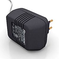
Power adapter
...free 3d model power adapter for download as max, obj, and fbx on turbosquid: 3d models for games, architecture, videos. (1510024)
turbosquid
$8
USB adapter
...e 3d model usb adapter for download as max, fbx, obj, and dwg on turbosquid: 3d models for games, architecture, videos. (1713542)
turbosquid
$30
adapter.3ds
... available on turbo squid, the world's leading provider of digital 3d models for visualization, films, television, and games.
turbosquid
$15
Nokia Adapter
... available on turbo squid, the world's leading provider of digital 3d models for visualization, films, television, and games.
turbosquid
$15
Universal adapter
... available on turbo squid, the world's leading provider of digital 3d models for visualization, films, television, and games.
Post
archibase_planet
free

Post
...post
archibase planet
barrier pole post pillar
fence post 11 - 3d model (*.gsm+*.3ds) for interior 3d visualization.
3d_ocean
$1

Post-it
...emporary website: http://marcinbauer.com ) features: - easy switch of post-it texture and color - you can very easily change t...
3d_ocean
$2

Post-It
...st-it tack tic work
*originally created in blender 3d. exported to different formats: .obj;.3ds;.blend;.dae;.fbx;.ply;.x3d;.mtl .
3d_export
free

Post
...post
3dexport
turbosquid
$7

Post
...lty free 3d model post for download as max, obj, fbx, and stl on turbosquid: 3d models for games, architecture, videos. (1150679)
3d_export
$5

sidewalk post
...sidewalk post
3dexport
sidewalk post
turbosquid
free

Post
... available on turbo squid, the world's leading provider of digital 3d models for visualization, films, television, and games.
3d_export
$5

post box
...post box
3dexport
american post box
archibase_planet
free

Steel Post
...steel post
archibase planet
fence balustrade
balustrade steel post
archibase_planet
free

Guard post
...base planet
guard post checkpoint building check point
guard post n191015 - 3d model (*.gsm+*.3ds) for exterior 3d visualization.