Thingiverse
SAMBUCCA - Chassis - Level 1 - Power by hede3D
by Thingiverse
Last crawled date: 3 years, 3 months ago
S.A.M.B.U.C.C.A.
L E V E L 1 - P O W E R
Deutsch
Es hat nun etwas gedauert, aber hier ist es: das nächste Level! Wer noch nicht weiß worum es geht, der schaut in der Linkliste weiter unten nach dem ersten Teil (Level 0) von SAMBUCCA, dort wird erklärt was SAMBUCCA ist. Dort habe ich auch versprochen in diesem Teil zu erklären warum ich dieses Projekt mache. Nun, eigentlich kann man mit dem fertigen SAMBUCCA nicht so viel machen. Man kann etwas damit spielen, das war es aber auch schon. Aber der Weg ist bekanntlich das Ziel, und so lernt man bei der Entstehung dieses Vehikels viel über Microcontroller, Programmieren, Schaltungsentwurf, Zusammenspiel von Teilen, Mechanik, Mathematik, Umgang mit Werkzeugen und Software. Theoretisch also ein Lern-Projekt für den Schreibtisch. Darum also, weil ich herausfinden will ob ich es kann.
Aufgabe dieses Levels von SAMBUCCA
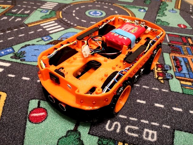
Hier finden Akku und Hauptschalter, sowie ein Anschluss zum Laden der Akkus platz. Welchen Akku ihr verwendet bleibt euch überlassen, ich verwende einen älteren 9,6V RC Akku aus 8 Zellen. Befestigen könnt ihr Ihn mit Klettband (so wie ich) oder mit Kabelbindern.
Unter dem Akku befinden sich die Gabellichtschranken für die Encoder-Scheiben der Motoren aus Level 0. Je nach verwendeter Gabellichtschranke benötigt ihr ein paar Distanzen um diese in die richtige Höhe zu heben.
Weiterhin finden sich hier bis zu 44 Stück 5mm LEDs. Diese können für lustige Animationen oder als Debug und Status-LEDs verwendet werden. So können sie als optisches Feedback für zum Beispiel die Fahrtrichtung, den Akkustand, Warnung, Annäherung oder sonstige Zustände genutzt werden. Einzelne LEDs können dabei einzelnen Sensoren zugeordnet sein und so den Schaltzustand anzeigen. Euch fällt da schon was ein. :)
Im vorderen Teil befinden sich 24 LEDs im hinteren Teil 20. Beide Teile habe ich sowohl mit als auch ohne Löcher für die LEDs entworfen, so sind Kombinationen möglich.
Als Ansteuerung für die LEDs verwende ich einen MAX7219CNG. Der Hardwareaufbau und das Pinout des MAX sind im Test-Sketch als Kommentare enthalten.
Benötigte Teile
MAX7219CNG
Experimentier-Platine, 10kOhm, 27kOhm, 10µF, 100nF, Stecker
0 / 24 / 20 / 44 Stück 5mm LED rot
2 Stück Gabellichtschranke für Arduino
Schalter
Power-Jack
Akkupack
Wichtig
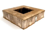
Das große Loch im hintern Teil signalisiert, dass dieser Platz frei bleiben sollte. Der Grund liegt im nächsten Level, denn dort ist der Greifer untergebracht und hier braucht es den Platz für den Servo-Motor!
Zugehörige Things:
Chassis - Level 0 - Drive: https://www.thingiverse.com/thing:4660593Chassis - Accessories: https://www.thingiverse.com/thing:4669691
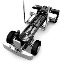
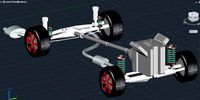
An dieser Stelle wieder die vorläufige Design-Studie:
Wenn es dir gefällt:
Hoffe jemand kann es gebrauchen.
Wenn es jemand baut, dann bitte unbedingt ein "Make" posten, ich will wissen was Ihr daraus macht!
:)
Bleibt gesund!
English
(Google-Translation)
It took a while, but here it is: the next level! If you do not yet know what it is about, look in the link list below for the first part (level 0) of SAMBUCCA, which explains what SAMBUCCA is. There I promised to explain in this part why I am doing this project. Well, actually you can't do that much with the finished SAMBUCCA. You can play with it, but that's about it. But the journey is the goal, as is well known, and so you learn a lot about microcontrollers, programming, circuit design, the interaction of parts, mechanics, mathematics, handling tools and software when creating this vehicle. In theory, a learning project for the desk. So it's because I want to find out if I can.
Abandonment of this level by SAMBUCCA
The battery and main switch as well as a connection for charging the batteries can be found here. Which battery you use is up to you, I use an older 9.6V RC battery with 8 cells. You can fix it with Velcro (like me) or with cable ties.
The fork light barriers for the encoder disks of the motors from level 0 are located under the battery. Depending on the fork light barrier used, you need a few distances to lift them to the correct height.
There are also up to 44 5mm LEDs here. These can be used for fun animations or as debug and status LEDs. For example, they can be used as visual feedback for the direction of travel, the battery level, warning, approach or other conditions. Individual LEDs can be assigned to individual sensors and thus indicate the switching status. You can think of something. :)
In the front part there are 24 LEDs in the back part 20. I designed both parts with and without holes for the LEDs, so combinations are possible.
I use a MAX7219CNG to control the LEDs. The hardware structure and the pinout of the MAX are included in the comments of the test sketch.
Required parts
MAX7219CNG
Experimental board, 10kOhm, 27kOhm, 10µF, 100nF, plug
0/24/20/44 pieces 5mm LED red
2 fork light barriers for Arduino
Switch
Power jack
Battery pack
Important
The large hole in the rear part signals that this space should remain free. The reason is on the next level, because this is where the gripper is located and this is where the servo motor is needed!
Related things:
Chassis - Level 0 - Drive : https://www.thingiverse.com/thing:4660593 Chassis - Accessories : https://www.thingiverse.com/thing:4669691
If you like it:
Hope someone can use it.
If someone builds it, please post a "Make", I want to know what you do with it!
:)
Stay healthy!
L E V E L 1 - P O W E R
Deutsch
Es hat nun etwas gedauert, aber hier ist es: das nächste Level! Wer noch nicht weiß worum es geht, der schaut in der Linkliste weiter unten nach dem ersten Teil (Level 0) von SAMBUCCA, dort wird erklärt was SAMBUCCA ist. Dort habe ich auch versprochen in diesem Teil zu erklären warum ich dieses Projekt mache. Nun, eigentlich kann man mit dem fertigen SAMBUCCA nicht so viel machen. Man kann etwas damit spielen, das war es aber auch schon. Aber der Weg ist bekanntlich das Ziel, und so lernt man bei der Entstehung dieses Vehikels viel über Microcontroller, Programmieren, Schaltungsentwurf, Zusammenspiel von Teilen, Mechanik, Mathematik, Umgang mit Werkzeugen und Software. Theoretisch also ein Lern-Projekt für den Schreibtisch. Darum also, weil ich herausfinden will ob ich es kann.
Aufgabe dieses Levels von SAMBUCCA
Hier finden Akku und Hauptschalter, sowie ein Anschluss zum Laden der Akkus platz. Welchen Akku ihr verwendet bleibt euch überlassen, ich verwende einen älteren 9,6V RC Akku aus 8 Zellen. Befestigen könnt ihr Ihn mit Klettband (so wie ich) oder mit Kabelbindern.
Unter dem Akku befinden sich die Gabellichtschranken für die Encoder-Scheiben der Motoren aus Level 0. Je nach verwendeter Gabellichtschranke benötigt ihr ein paar Distanzen um diese in die richtige Höhe zu heben.
Weiterhin finden sich hier bis zu 44 Stück 5mm LEDs. Diese können für lustige Animationen oder als Debug und Status-LEDs verwendet werden. So können sie als optisches Feedback für zum Beispiel die Fahrtrichtung, den Akkustand, Warnung, Annäherung oder sonstige Zustände genutzt werden. Einzelne LEDs können dabei einzelnen Sensoren zugeordnet sein und so den Schaltzustand anzeigen. Euch fällt da schon was ein. :)
Im vorderen Teil befinden sich 24 LEDs im hinteren Teil 20. Beide Teile habe ich sowohl mit als auch ohne Löcher für die LEDs entworfen, so sind Kombinationen möglich.
Als Ansteuerung für die LEDs verwende ich einen MAX7219CNG. Der Hardwareaufbau und das Pinout des MAX sind im Test-Sketch als Kommentare enthalten.
Benötigte Teile
MAX7219CNG
Experimentier-Platine, 10kOhm, 27kOhm, 10µF, 100nF, Stecker
0 / 24 / 20 / 44 Stück 5mm LED rot
2 Stück Gabellichtschranke für Arduino
Schalter
Power-Jack
Akkupack
Wichtig
Das große Loch im hintern Teil signalisiert, dass dieser Platz frei bleiben sollte. Der Grund liegt im nächsten Level, denn dort ist der Greifer untergebracht und hier braucht es den Platz für den Servo-Motor!
Zugehörige Things:
Chassis - Level 0 - Drive: https://www.thingiverse.com/thing:4660593Chassis - Accessories: https://www.thingiverse.com/thing:4669691
An dieser Stelle wieder die vorläufige Design-Studie:
Wenn es dir gefällt:
Hoffe jemand kann es gebrauchen.
Wenn es jemand baut, dann bitte unbedingt ein "Make" posten, ich will wissen was Ihr daraus macht!
:)
Bleibt gesund!
English
(Google-Translation)
It took a while, but here it is: the next level! If you do not yet know what it is about, look in the link list below for the first part (level 0) of SAMBUCCA, which explains what SAMBUCCA is. There I promised to explain in this part why I am doing this project. Well, actually you can't do that much with the finished SAMBUCCA. You can play with it, but that's about it. But the journey is the goal, as is well known, and so you learn a lot about microcontrollers, programming, circuit design, the interaction of parts, mechanics, mathematics, handling tools and software when creating this vehicle. In theory, a learning project for the desk. So it's because I want to find out if I can.
Abandonment of this level by SAMBUCCA
The battery and main switch as well as a connection for charging the batteries can be found here. Which battery you use is up to you, I use an older 9.6V RC battery with 8 cells. You can fix it with Velcro (like me) or with cable ties.
The fork light barriers for the encoder disks of the motors from level 0 are located under the battery. Depending on the fork light barrier used, you need a few distances to lift them to the correct height.
There are also up to 44 5mm LEDs here. These can be used for fun animations or as debug and status LEDs. For example, they can be used as visual feedback for the direction of travel, the battery level, warning, approach or other conditions. Individual LEDs can be assigned to individual sensors and thus indicate the switching status. You can think of something. :)
In the front part there are 24 LEDs in the back part 20. I designed both parts with and without holes for the LEDs, so combinations are possible.
I use a MAX7219CNG to control the LEDs. The hardware structure and the pinout of the MAX are included in the comments of the test sketch.
Required parts
MAX7219CNG
Experimental board, 10kOhm, 27kOhm, 10µF, 100nF, plug
0/24/20/44 pieces 5mm LED red
2 fork light barriers for Arduino
Switch
Power jack
Battery pack
Important
The large hole in the rear part signals that this space should remain free. The reason is on the next level, because this is where the gripper is located and this is where the servo motor is needed!
Related things:
Chassis - Level 0 - Drive : https://www.thingiverse.com/thing:4660593 Chassis - Accessories : https://www.thingiverse.com/thing:4669691
If you like it:
Hope someone can use it.
If someone builds it, please post a "Make", I want to know what you do with it!
:)
Stay healthy!
Similar models
thingiverse
free

Education Rover - programmable with Python by niewall
...hmen einer besonderen lernleistung und kann frei verwendet und weiterentwickelt werden. bei fragen stehe ich gerne zur verfügung.
thingiverse
free

Bed Leveler Knob for Ender V2 by Benibenito
...lt die mutter optimal und verrutscht nicht.
ich habe die level räder mit petg gedruckt, da das hotbed doch etwas wärme abstrahlt.
thingiverse
free

Hit Me Target für DR!FT Sturmkind Strecke by Ma_Bo_Thing
... ich die base mit uhu patafix auf der strecke befestigt, so kann ich diese immer wieder demontieren und an anderer stelle nutzen.
thingiverse
free

Nozzle und Throat Cooling Kühlung Anet E10 by Utz
...edruckt, diese nochmals nachgebohrt mit einem 2,5mm bohrer und die gewinde reingebohrt. die durchgangslöcher mit 3mm nachgebohrt.
thingiverse
free

Helfende Hand Basis (Helping Hand Base) by Dr_Peacock
... bilder.
die base ist 12cm von seite zu seite.
kritik, lob oder verbesserungsvorschläge könnt ihr gerne als comment hinterlassen.
thingiverse
free

Halter für Trelock Akku Fahrradlampe LS 950 Alternative zu ZL 700 by Pigcom
...eichter rasteffekt zwischen lenkeradapter und lampenadapter erzielt. generell habe ich überall selbstsichernde muttern verwendet.
thingiverse
free

Legenden von Andor - Einsatz der Sternenschild by Moly2201
...nn.
als kleber habe ich ein kunststoffkleber auf n-butylacetat-basis verwendet, hält bombenfest und duftet beim kleben auch gut.
thingiverse
free

Druckluft Motor by DDDUM
... und steueröffnung auf der kurbelwelle!
leider kann ich die teile nicht weiter bearbeiten, weil ich das programm nicht mehr habe.
thingiverse
free

Halter für Lupenbrille by Hans_n
... nachgebaut.
es kann sein, dass die rundung minimal zu dick ist, dann müsst ihr was abtragen, aber es soll nun mal streng sitzen.
3dwarehouse
free

Blache Design - Mercedes-Benz Penthaus
... die solarpanele im verbrauch von strom deutlich effizienter und bietet platz für alle zu tätigenden arbeiten in der bürobranche.
Sambucca
thingiverse
free

SAMBUCCA - Chassis - Accessories by hede3D
...pe someone can use it.
if someone builds it, please post a "make", i want to know what you do with it!
:)
stay healthy!
thingiverse
free

SAMBUCCA - Chassis - Level 0 - Drive by hede3D
...pe someone can use it.
if someone builds it, please post a "make", i want to know what you do with it!
:)
stay healthy!
Hede3D
thingiverse
free

Anet A8 MicroSD-USB Adapter Holder by hede3D
...et a8 microsd to usb adapter. mount it with selfadhesive tape on the bottomside.
printable without supports.
hope you like it. ;)
thingiverse
free

Corner protector for 15mm plate. by hede3D
...total external dimensions
countersunk hole 3mm for fastening with screw on the underside.
hope it is useful.
hope you like it. :)
thingiverse
free

Key Cap Set for DIY TC-1212T Microswitch Keyboard by hede3D
...caps for microswitches typ tc-1212t in a finger friendly retro style design. :)
update 2020-11-03:
rework the bottom of the caps.
thingiverse
free

Add On 2 for my Key Cap Set for DIY TC-1212T Microswitch by hede3D
...oswitch by hede3d
thingiverse
this is the second addon set for my keycap set published 2020-11-03.
including math keys
have fun!
thingiverse
free

Add On 1 for my Key Cap Set for DIY TC-1212T Microswitch by hede3D
...de3d
thingiverse
this is the first addon set for my keycap set published 2020-11-03.
including special and office keys
have fun!
thingiverse
free

Container for Amazon Fire TV 4K by hede3D
...st up a little bit so that it fits more easily. (if you want to)
its a thing for travelers.
hope its useful.
hope you like it. :)
thingiverse
free

Corner protector for 6,8,10,12,13,15,18,20,21,24 or 25mm plates by hede3D
...)
24mm (28mm)
25mm (29mm)
countersunk hole 3mm for fastening with screw on the underside.
hope it is useful.
hope you like it. :)
thingiverse
free

Extension boxes for my Bench ATX PSU by hede3D
...
of course, you can wire them internally as you wish.
the back plate is identical for both boxes.
i hope you will find it useful.
thingiverse
free

(another) Anet A8 X-Belt Tensioner by hede3D
...part of the bearing securely so that no center screw is "sawed" any more.
hope it is useful to you ;)
hope you like it.
thingiverse
free

Wire reel with stackable storage box (easy to print) by hede3D
...and place on the first one. and so on. put the lid on top (box_lid.stl) and you're done.
easy right?
hope someone can use it.
Chassis
design_connected
$16

Chassis
...chassis
designconnected
wilkhahn chassis chairs computer generated 3d model. designed by stefan diez.
3d_export
$10

truck chassis
...truck chassis
3dexport
truck chassis
3d_export
$5
Truck chassis
...truck chassis
3dexport
truck chassis
3d_export
$5

buggy chassi
...buggy chassi 3dexport chassis of a simple ride...
turbosquid
$35

Chassis
...odel chassis for download as 3ds, dxf, obj, c4d, fbx, and stl on turbosquid: 3d models for games, architecture, videos. (1413332)
design_connected
$16

Chassis Armchair
...chassis armchair
designconnected
baxter chassis armchair armchairs computer generated 3d model. designed by n/a.
turbosquid
$25
DRONE CHASSIS
...bosquid
royalty free 3d model drone chassis for download as on turbosquid: 3d models for games, architecture, videos. (1699724)
turbosquid
$79

Car Chassis
...quid
royalty free 3d model car chassis for download as blend on turbosquid: 3d models for games, architecture, videos. (1593376)
turbosquid
$50
Car Chassis
...osquid
royalty free 3d model car chassis for download as dwg on turbosquid: 3d models for games, architecture, videos. (1164087)
turbosquid
$75

Chassis 8x8
...free 3d model chassis 8x8 for download as ige, obj, and sldas on turbosquid: 3d models for games, architecture, videos. (1221250)
Level
design_connected
$11
Levels
...levels
designconnected
one nordic levels computer generated 3d model. designed by form us with love.
design_connected
$7
Level
...level
designconnected
zanotta level shelves and storage computer generated 3d model. designed by arik levy.
turbosquid
$29
level
...ty free 3d model level for download as 3ds, obj, c4d, and fbx on turbosquid: 3d models for games, architecture, videos. (1272856)
turbosquid
$1
level
... available on turbo squid, the world's leading provider of digital 3d models for visualization, films, television, and games.
3d_export
$5
Mario level
...mario level
3dexport
mario level low quality for fun videos
3ddd
$1
LEVELS OF DISCOVERY
...етская мебель "levels of discovery". rab10003 princess mini rocker
кресло-качалка (мини) "принцесса навсегда"
3d_export
$19
level design
...level design
3dexport
you can use this design (level design) in your own game.
turbosquid
$60
Desert level
...squid
royalty free 3d model desert level for download as fbx on turbosquid: 3d models for games, architecture, videos. (1208131)
turbosquid
$15
Transit Level
...quid
royalty free 3d model transit level for download as max on turbosquid: 3d models for games, architecture, videos. (1158112)
turbosquid
$14

Districts Level
...id
royalty free 3d model districts level for download as max on turbosquid: 3d models for games, architecture, videos. (1408410)
Power
turbosquid
$100
power
...ower
turbosquid
royalty free 3d model power for download as on turbosquid: 3d models for games, architecture, videos. (1421990)
3d_export
$5

Power
...power
3dexport
3d_export
$5
power outlets
...power outlets
3dexport
power outlets
3ddd
$1
lion power
...lion power
3ddd
лев , статуя
lion power gold sculpture
3ddd
$1
Sea Power
...
компас , море , часы
часы с компасом sea power
3ddd
free
Meridiani / Power
...power
3ddd
meridiani , круглый
стол power производитель meridiani, диаметр 120,высота 67
3d_export
$5

Power Surge
...power surge
3dexport
the power surge is a all mesh carnival ride to lower in game part count and lag
turbosquid
$8
Airport Ground Power Unit (AXA Power )
... available on turbo squid, the world's leading provider of digital 3d models for visualization, films, television, and games.
turbosquid
$50

Power Houser
...rbosquid
royalty free 3d model power houser for download as on turbosquid: 3d models for games, architecture, videos. (1333800)
3d_export
$5

power outlet
...power outlet
3dexport
power outlet<br>format file maya 2018, 3d max 2017, obj, fbx
1
turbosquid
$69
armchairs(1)(1)
... available on turbo squid, the world's leading provider of digital 3d models for visualization, films, television, and games.
turbosquid
$15
ring 1+1
... available on turbo squid, the world's leading provider of digital 3d models for visualization, films, television, and games.
turbosquid
$10
chair(1)(1)
... available on turbo squid, the world's leading provider of digital 3d models for visualization, films, television, and games.
turbosquid
$8

Chair(1)(1)
... available on turbo squid, the world's leading provider of digital 3d models for visualization, films, television, and games.
turbosquid
$2

RING 1(1)
... available on turbo squid, the world's leading provider of digital 3d models for visualization, films, television, and games.
turbosquid
$1
house 1(1)
... available on turbo squid, the world's leading provider of digital 3d models for visualization, films, television, and games.
turbosquid
$1

Table 1(1)
... available on turbo squid, the world's leading provider of digital 3d models for visualization, films, television, and games.
turbosquid
$59
Formula 1(1)
...lty free 3d model formula 1 for download as max, fbx, and obj on turbosquid: 3d models for games, architecture, videos. (1567088)
design_connected
$11
No 1
...no 1
designconnected
sibast no 1 computer generated 3d model. designed by sibast, helge.
turbosquid
$2
desert house(1)(1)
...3d model desert house(1)(1) for download as 3ds, max, and obj on turbosquid: 3d models for games, architecture, videos. (1055095)