GrabCAD

RTP - Robotic Test Platform (drone/robot)
by GrabCAD
Last crawled date: 1 year, 11 months ago
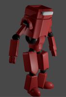
Me and a friend of mine are working on a new project which we want to share with other enthusiasts. We have been experimenting with Atmel AVR's for a while, and have quite an assortment of Arduino boards and extension modules. However, we never did anything more with this then some bench testing, up until now!
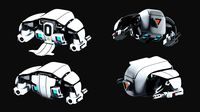
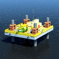
We decided to build a robotic test platform which will be suitable to test numerous electronic circuits and programs on. (Thus the name RTP) It started with some plans for a small wooden platform and some transmission motors, but quickly got up scaled to something that could autonomous drive outside. Our plan is to equip the robot with sensors, cameras and a GPS receiver and be able to set up a traveling route with the computer, tablet or smartphone.
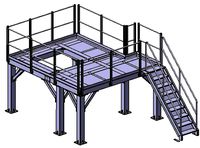
After some research on the standard hardware parts, motors, electronics and batteries we started designing the robot using SolidWorks. We came up with frame constructed out of sheet metal which will form the base of the robot. For the drive train our choice went out to two 500W 24V electric bike motors powered by six 12V 7Ah SLA batteries. To controll the speed of the motors we got our hands on two 36V 70A speed controllers, which are perfect for the project, because they support both a PWM input signal as a RS232 connection.
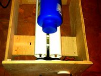
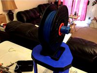
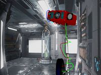
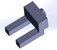
Before we started building the real frame we wanted to check that we don't have any issues with the drive train. We build a temporally test-setup providing the ability to test the motors, speed controllers and transmission. In the video below you see some footage of the first tests we did. It might look that one of the shafts is bend, but this was only a bearing which twisted in its housing due to the miss alignment of one of the gears. (Fixed eventually!) After the tests we changed the positions of some gears, but nothing really spectacular.
The next step was the actual building of the machine. Luckily we had access to a nice workshop with all the tools we needed. (laser cutting machine, press brake, lathe, mill and proper welding equipment) This made building an ease and we got most of the work done in a weekend.
After the frame assembly we test-fitted all the parts. This meant assembling the whole machine, and gave us the opportunity to drive around for the first time. As you can see the batteries and electronics where mounted on top of the machine as their position of their mounting brackets still needed to be determined.
All of the parts fitted perfect, and even more important, the robot drove pretty good! We took it completely apart and sandblasted most of the components. This didn't only remove most of the sharp edged and grinding marks, it also provided a good bare metal surface for the powder coating to stick to. We chose for a dark grey textured coating which came out awesome! We started assembling the robot and took the pictures shown below.
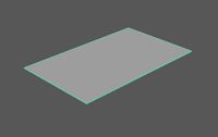
The final step was creating the bottom, top, front and rear panels to close of the internal parts and protect them from any dirt, sand and water. For these panels we chose a lighter grey which looks good next to the dark grey and yellow.
Images can be found on: http://gallery.datmartens.com/?jgall_dir=Robots%2FRTP+-+Robotic+Test+Platform%2F&
Videos can be found on: http://www.youtube.com/playlist?list=PLlnGjcgHt2j4g7yaxNasGGMuws9Ea-aE-
As said before, this is a projects that I’m working on together with Stef van Itterzon. Be sure to check out his website: www.svitterzon.nl
We decided to build a robotic test platform which will be suitable to test numerous electronic circuits and programs on. (Thus the name RTP) It started with some plans for a small wooden platform and some transmission motors, but quickly got up scaled to something that could autonomous drive outside. Our plan is to equip the robot with sensors, cameras and a GPS receiver and be able to set up a traveling route with the computer, tablet or smartphone.
After some research on the standard hardware parts, motors, electronics and batteries we started designing the robot using SolidWorks. We came up with frame constructed out of sheet metal which will form the base of the robot. For the drive train our choice went out to two 500W 24V electric bike motors powered by six 12V 7Ah SLA batteries. To controll the speed of the motors we got our hands on two 36V 70A speed controllers, which are perfect for the project, because they support both a PWM input signal as a RS232 connection.
Before we started building the real frame we wanted to check that we don't have any issues with the drive train. We build a temporally test-setup providing the ability to test the motors, speed controllers and transmission. In the video below you see some footage of the first tests we did. It might look that one of the shafts is bend, but this was only a bearing which twisted in its housing due to the miss alignment of one of the gears. (Fixed eventually!) After the tests we changed the positions of some gears, but nothing really spectacular.
The next step was the actual building of the machine. Luckily we had access to a nice workshop with all the tools we needed. (laser cutting machine, press brake, lathe, mill and proper welding equipment) This made building an ease and we got most of the work done in a weekend.
After the frame assembly we test-fitted all the parts. This meant assembling the whole machine, and gave us the opportunity to drive around for the first time. As you can see the batteries and electronics where mounted on top of the machine as their position of their mounting brackets still needed to be determined.
All of the parts fitted perfect, and even more important, the robot drove pretty good! We took it completely apart and sandblasted most of the components. This didn't only remove most of the sharp edged and grinding marks, it also provided a good bare metal surface for the powder coating to stick to. We chose for a dark grey textured coating which came out awesome! We started assembling the robot and took the pictures shown below.
The final step was creating the bottom, top, front and rear panels to close of the internal parts and protect them from any dirt, sand and water. For these panels we chose a lighter grey which looks good next to the dark grey and yellow.
Images can be found on: http://gallery.datmartens.com/?jgall_dir=Robots%2FRTP+-+Robotic+Test+Platform%2F&
Videos can be found on: http://www.youtube.com/playlist?list=PLlnGjcgHt2j4g7yaxNasGGMuws9Ea-aE-
As said before, this is a projects that I’m working on together with Stef van Itterzon. Be sure to check out his website: www.svitterzon.nl
Similar models
grabcad
free

Truck Engine Transmission Block
...ss. transmissions are also used on pedal bicycles, fixed machines, and where different rotational speeds and torques are adapted.
cg_trader
free

Truck Engine Transmission Block
...ss. transmissions are also used on pedal bicycles, fixed machines, and where different rotational speeds and torques are adapted.
cg_trader
$9

Gearbox
... transition tran diff shaft teeth rack robot pbr industrial machine industrial machine industrial part gear rack industrial robot
grabcad
free

Gear box
...nsmission is a type of gearbox that can be "shifted" to dynamically change the speed-torque ratio such as in a vehicle.
grabcad
free

QRM - Quad Rotor Mini
...adcopter is only 176x176mm and will have a rtf flying weight of about 325grams. we gave it the name qrm, meaning quad rotor mini.
grabcad
free

BLDC Motor
...ing are linear motors, servomotors, actuators for industrial robots, extruder drive motors and feed drives for cnc machine tools.
grabcad
free

multiple disc clutch
...some diesel locomotives with mechanical transmissions. it is also used in some electronically controlled all-wheel drive systems.
grabcad
free

Differential Drive Robot
...out design. no supports are needed during printing.
you can also view my youtube video, which demonstrates the assembly sequence.
grabcad
free

ESC
...c
grabcad
an electronic speed control (esc) is an electronic circuit that controls and regulates the speed of an electric motor.
thingiverse
free
Rock tumbler by papergeek
... the amount of starting current is too great for a basic power supply.
see assembly instructions for details on materials used.
Rtp
3d_export
$5
Dish01 3D Model
...model 3dexport dish table dish glass dish01 3d model rtp 66671...
thingiverse
free
Nautilus Gears RTP by JrDesigner
...nautilus gears rtp by jrdesigner
thingiverse
fun gears to play with
thingiverse
free
Glock 26 Magazine Extension Grip 26/27/33/39 by RTP
... the extension grip printed flat and upside down, instead of at an angle.
bitcoin donations: 1em2kgnguxsi9gybvasiwgpqhsbnbs4qpt
thingiverse
free
SeeMeCNC Eris Delta Top Spool Holder by Djkirkendall
...sketchy side-spooler that comes with the seemecnc eris delta rtp printer. you'll need to print: 2 x 52mm spool...
thingiverse
free
Microphone Module I2S Interface Case
...you can use the command cvlc -vvv alsa://dmic_sv --sout '#transcode{acodec=ulaw}:rtpsdp=rstp://:8554}' to stream audio available at vlc rtsp://your.pi.ip.address:8554/ you will...
thingiverse
free

Small Parts Organizer Bins (3 Sizes) by Makersworkshopllc
...3d filament, blue pla: https://amzn.to/2iwqudw artemis 300 3d printer: https://www.seemecnc.com/products/artemis-300-rtpeslide-motion if you found this helpful please consider following and...
grabcad
free

RTP Pockels Cell
...-optically pockels cell switch, based of two rtp (rubidium titanyl phosphate – rbtiopo4) crystals in thermal compensative scheme.
grabcad
free

Reise-Tauchsieder "RTP 3040" im Polybeutel
...reise-tauchsieder "rtp 3040" im polybeutel
grabcad
heater
grabcad
free

https://www.dewa33g.com/
...online terbaik yang menyediakan permainan slot gacor terbaru dengan rtp 98%....
Drone
3d_export
$12
Drones
...drones
3dexport
drones
3d_export
$5
drone
...drone
3dexport
drone
3d_export
$6
drone
...drone
3dexport
high poly model of dji phantom 4 (drone)
3d_export
$5
drone
...drone
3dexport
drone military flight, sizes are in mm, modeled in fision 360
3d_export
free
drone
...drone
3dexport
drone de uso tactico, creado en blender version 2.79
3d_export
$35
DRONE
...drone
3dexport
turkey drone alpagu kamikaze foldable wing 3ds max 2019,2020,2021,2022 vray 5.00 rendered
3d_ocean
$29

Drone
...drone camera drone electronics justtomas military parrot plane robot sci-fi spy toy vehicle
drone by justtomas .c4d r16 .obj .3ds
turbosquid
$6

Drone
...rone
turbosquid
royalty free 3d model drone for download as on turbosquid: 3d models for games, architecture, videos. (1347051)
turbosquid
free
Drone
...drone
turbosquid
free 3d model drone for download as blend on turbosquid: 3d models for games, architecture, videos. (1688993)
turbosquid
$69
Drone
...e
turbosquid
royalty free 3d model drone for download as max on turbosquid: 3d models for games, architecture, videos. (1232508)
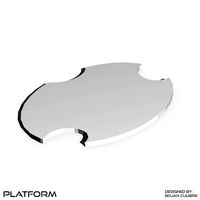
Platform
archibase_planet
free
Platform
...rm
archibase planet
platform
platform stefano galli savio cerrato n040413 - 3d model (*.gsm+*.3ds) for exterior 3d visualization.
turbosquid
$4
Platform
...d
royalty free 3d model platform for download as max and fbx on turbosquid: 3d models for games, architecture, videos. (1363559)
3d_export
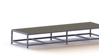
$5
WORKING PLATFORM
...working platform
3dexport
working platform 4000x3000x1500mm
turbosquid
$20
Platform
... available on turbo squid, the world's leading provider of digital 3d models for visualization, films, television, and games.
turbosquid
$9
Platform
... available on turbo squid, the world's leading provider of digital 3d models for visualization, films, television, and games.
turbosquid
$1
Platform
... available on turbo squid, the world's leading provider of digital 3d models for visualization, films, television, and games.
turbosquid
$1

Platform
... available on turbo squid, the world's leading provider of digital 3d models for visualization, films, television, and games.
turbosquid
$1

Platform
... available on turbo squid, the world's leading provider of digital 3d models for visualization, films, television, and games.
3d_ocean
$19
Drilling Platform
...rm for coastal areas. designed to perform drilling operations. include standart materials scene and v-ray scene with environment.
3d_export
$15
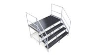
steel grill platform
...steel grill platform
3dexport
steel grill platform
Robot
3d_ocean
$20

Robot
...robot
3docean
character metal robot robot robotic white
robot model for 3dsmax 2009 and greater
3d_ocean
$45
Robot
...robot
3docean
fighing machine robot
a fighting robot from the scrapyard.
3d_ocean
$18
Robot
...robot
3docean
machin robot science fiction
high poly robot.
3d_export
$7
Robot
...robot
3dexport
robot
3d_export
$5
robot
...robot
3dexport
robot
3d_export
free

Robot
...robot
3dexport
robot
turbosquid
$10

Robot/ Alien Robot
...
royalty free 3d model robot/ alien robot for download as max on turbosquid: 3d models for games, architecture, videos. (1442828)
3d_export
$5

robot
...robot
3dexport
robot in blender
3ddd
$1
robot
...robot
3ddd
робот
robot
3ddd
$1

Robot
...robot
3ddd
робот
robot
Robotic
3d_ocean
$20
Robot
...robot 3docean character metal robot robot robotic white robot model for 3dsmax 2009 and...
3d_ocean
$45
Robot
...robot
3docean
fighing machine robot
a fighting robot from the scrapyard.
3d_ocean
$18
Robot
...robot
3docean
machin robot science fiction
high poly robot.
3d_export
$7
Robot
...robot
3dexport
robot
3d_export
$5
robot
...robot
3dexport
robot
3d_export
free
Robot
...robot
3dexport
robot
turbosquid
$10
Robot/ Alien Robot
...
royalty free 3d model robot/ alien robot for download as max on turbosquid: 3d models for games, architecture, videos. (1442828)
3d_export
$5
robot
...robot
3dexport
robot in blender
3ddd
$1
robot
...robot
3ddd
робот
robot
3ddd
$1
Robot
...robot
3ddd
робот
robot
Test
turbosquid
$99
test
...st
turbosquid
royalty free 3d model test for download as max on turbosquid: 3d models for games, architecture, videos. (1251637)
turbosquid
$63
TEST
...st
turbosquid
royalty free 3d model test for download as max on turbosquid: 3d models for games, architecture, videos. (1446233)
turbosquid
$1
test
...st
turbosquid
royalty free 3d model test for download as fbx on turbosquid: 3d models for games, architecture, videos. (1360941)
3d_export
free

johnny test
...johnny test
3dexport
johnny test 3d
turbosquid
$15

Test
... available on turbo squid, the world's leading provider of digital 3d models for visualization, films, television, and games.
turbosquid
$2

test
... available on turbo squid, the world's leading provider of digital 3d models for visualization, films, television, and games.
turbosquid
free

Test
... available on turbo squid, the world's leading provider of digital 3d models for visualization, films, television, and games.
turbosquid
free

test
... available on turbo squid, the world's leading provider of digital 3d models for visualization, films, television, and games.
turbosquid
free

Test
... available on turbo squid, the world's leading provider of digital 3d models for visualization, films, television, and games.
3d_export
$5
gripper test
...gripper test
3dexport
robot gripper test model