Thingiverse

RPi Meteor Camera by mjmazur
by Thingiverse
Last crawled date: 3 years, 1 month ago
Introduction
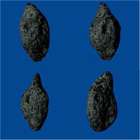
Every day, 10’s of tons of extra-terrestrial material falls onto the Earth. Although most of the particles are no bigger than grains of sand, when they hit our atmosphere they create the flashes of light that we often call ‘shooting stars.’ These meteors, as they are more properly known, occur at altitudes of between about 70 and 110km and are moving at speeds of between 11 and 72 km/s. And, with millions visible to the naked eye each day, we can’t help but wonder what they are and where they come from. To try to answer these questions, there are a number of different techniques that can be used. Two of the most basic are radar and optical observations. Radar is incredibly useful as it allows us to observe and compute orbits for some of the smallest particles that impact the Earth. However, it’s too costly for the amateur to produce meaningful information. Good optical observations, however, can be made cheaply and easily with a few pieces of basic equipment. Here, we describe an opensource project to build a very capable meteor camera that can be connected to a global meteor camera network.
The project can be found on GitHub at, https://github.com/CroatianMeteorNetwork/RMS
What You Need
A surprisingly capable meteor camera requires relatively few parts and can be built over the course of an evening or two. Here's what you'll need...
IP camera module with Sony IMX225 (discontinued) or IMX291 sensor
CS lens mount
4 mm f1.2 CS-mount lens (you can also use a 2.8 mm or a 6 mm if you want a wider or narrower field)
POE module for IP camera
IP/POE cable
POE injector
Raspberry Pi 3 Model B/B+
64GB SD card
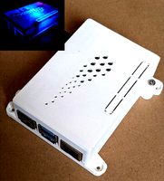
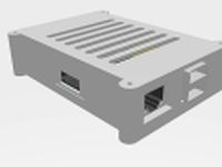
RPi case with fan and space for the RTC module
RTC module
Waterproof enclosure
Mounting bracket
2 network cables
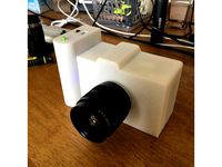
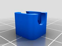
For the enclosure, you can either buy one commercially or print your own from the files included here. Printing your own has the advantage of being lightweight and can make use of a smaller mounting bracket than required by a commercial housing. If you decide to print your own, you'll also need the following parts.
47 mm diameter glass window
70 mm o-ring
1/4" nut
M2 standoffs 5 or 10mm
Silicone sealant
If you have trouble finding any of the required parts, send us a note. We can put together a small kit of tested parts for a reasonable cost.
How To Do It
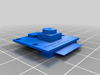
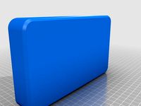
Print out the housing parts.
Drill a hole in the bottom corner of large enough to pass the IP/POE cable connectors through.
Run a thin bead of silicone along the inside edge of the seat for the window in the housing top.
Set the window onto the bead of silicone and press down lightly to ensure that a seal is made.
Place the o-ring around the threads of the housing base.
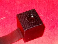
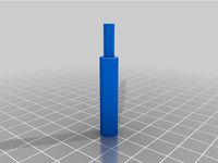
Insert a 1/4" nut into the hexagonal depression in the housing base and then screw the tripod mount into the nut.
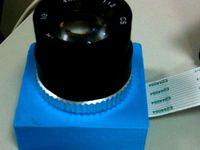
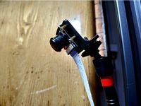
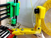
Peel the protective film (if there is one) off the front of the sensor of the camera module and attach a CS lens mount to the module.
Screw the 4 mm lens into the lens mount
Run the IP/POE cable connectors through the hole in the housing and then connect them to the POE module.
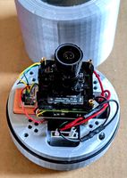
Attach the POE module to the camera base with 4 standoffs. If the threads on the standoffs aren't long enough, you may need to first screw four 5 mm standoffs into the base. The POE module can then be attached to these with 10/15 mm standoffs.
Run POE module cable to the camera module.
Attach the camera module to the 10/15 mm standoffs.
Screw the housing top to the base to check the fit. If the front of the lens is more than 5 mm from the window, you can add an additional set of 5 mm standoffs between the POE and camera modules.
Plug your camera into the POE injector and then into the ethernet connector on your computer.
Setup up your ethernet adapter to have an IP address of something like 192.168.1.5 (your camera is likely 192.168.1.10 from the factory) and your subnet and gateway as 255.255.255.0 and 192.168.1.0 respectively.
Plug the injector into the wall.
Run the CMS software (likely a download from your camera supplier) and add the camera as a device with IP address 192.168.1.10 (or whatever the camera address is).
Set the camera settings and finally the camera IP address as 192.168.42.10.
Take a break, and admire your handiwork. Your camera is now assembled and ready to be mounted and plugged into the Pi.
Find a mounting spot for your camera. The location should allow the camera to look up and be as free from obstructions as possible.
Mount the camera securely and run your network cable back to the POE injector which is, preferably, inside with the RPi.
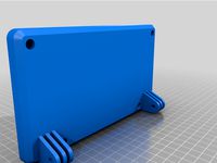
Assemble your RPi case and insert the RPi.
Install the RTC module.
Burn the Raspberry Pi Meteor System image to your SD card
Insert the SD card into the Pi and boot it up.
Expand the filesystem, setup a new ssh key, and reboot.
Plug the camera into the POE injector and the injector into the ethernet port on the RPi.
Double-click on the RMS_ShowLiveStream shell script on your desktop and execute it in a terminal window. A window should pop up with you video feed. Kill it by typing CTRL-c in the terminal window that it's running under.
Open the RMS_config file on the Desktop with a file editor.
Update the file with your latitude, longitude, and elevation.
Update field-of-view if you're not using a 4 mm lens.
Save the file with CTRL-s and reboot the RPi.
If all went well, your Raspberry Pi Meteor System will automatically begin collecting data when the sun goes down. In the morning, detected meteors can be viewed with the CMN_binViewer application (found on the desktop).
Create a plate solution by doing a stellar calibration (a detailed description of how to do this can be found here... https://github.com/CroatianMeteorNetwork/RMS/blob/master/Guides/SkyFit.md )
Now in order to achieve the full power of the system, there should be another camera located some distance away that is observing the same volume as your camera. When this is the case, orbital information for the observed meteors can be calculated. In the event of a meteorite-dropping fireball, this information will give a good idea of where the burst occured and where meteorites may be found on the ground. To enable orbit calculations, you simply need to edit the upload_enabled flag to true. This will automatically upload your detected meteors to a server at the University of Western Ontario where they can be correlated with other nearby observations.
Need Help?
This has been a simplified overview of how to build your own meteor camera. More detailed documentation is available on the GitHub project page but we're here to answer any questions (related to meteor astronomy) you have.
Every day, 10’s of tons of extra-terrestrial material falls onto the Earth. Although most of the particles are no bigger than grains of sand, when they hit our atmosphere they create the flashes of light that we often call ‘shooting stars.’ These meteors, as they are more properly known, occur at altitudes of between about 70 and 110km and are moving at speeds of between 11 and 72 km/s. And, with millions visible to the naked eye each day, we can’t help but wonder what they are and where they come from. To try to answer these questions, there are a number of different techniques that can be used. Two of the most basic are radar and optical observations. Radar is incredibly useful as it allows us to observe and compute orbits for some of the smallest particles that impact the Earth. However, it’s too costly for the amateur to produce meaningful information. Good optical observations, however, can be made cheaply and easily with a few pieces of basic equipment. Here, we describe an opensource project to build a very capable meteor camera that can be connected to a global meteor camera network.
The project can be found on GitHub at, https://github.com/CroatianMeteorNetwork/RMS
What You Need
A surprisingly capable meteor camera requires relatively few parts and can be built over the course of an evening or two. Here's what you'll need...
IP camera module with Sony IMX225 (discontinued) or IMX291 sensor
CS lens mount
4 mm f1.2 CS-mount lens (you can also use a 2.8 mm or a 6 mm if you want a wider or narrower field)
POE module for IP camera
IP/POE cable
POE injector
Raspberry Pi 3 Model B/B+
64GB SD card
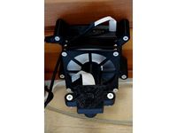
RPi case with fan and space for the RTC module
RTC module
Waterproof enclosure
Mounting bracket
2 network cables
For the enclosure, you can either buy one commercially or print your own from the files included here. Printing your own has the advantage of being lightweight and can make use of a smaller mounting bracket than required by a commercial housing. If you decide to print your own, you'll also need the following parts.
47 mm diameter glass window
70 mm o-ring
1/4" nut
M2 standoffs 5 or 10mm
Silicone sealant
If you have trouble finding any of the required parts, send us a note. We can put together a small kit of tested parts for a reasonable cost.
How To Do It
Print out the housing parts.
Drill a hole in the bottom corner of large enough to pass the IP/POE cable connectors through.
Run a thin bead of silicone along the inside edge of the seat for the window in the housing top.
Set the window onto the bead of silicone and press down lightly to ensure that a seal is made.
Place the o-ring around the threads of the housing base.
Insert a 1/4" nut into the hexagonal depression in the housing base and then screw the tripod mount into the nut.
Peel the protective film (if there is one) off the front of the sensor of the camera module and attach a CS lens mount to the module.
Screw the 4 mm lens into the lens mount
Run the IP/POE cable connectors through the hole in the housing and then connect them to the POE module.
Attach the POE module to the camera base with 4 standoffs. If the threads on the standoffs aren't long enough, you may need to first screw four 5 mm standoffs into the base. The POE module can then be attached to these with 10/15 mm standoffs.
Run POE module cable to the camera module.
Attach the camera module to the 10/15 mm standoffs.
Screw the housing top to the base to check the fit. If the front of the lens is more than 5 mm from the window, you can add an additional set of 5 mm standoffs between the POE and camera modules.
Plug your camera into the POE injector and then into the ethernet connector on your computer.
Setup up your ethernet adapter to have an IP address of something like 192.168.1.5 (your camera is likely 192.168.1.10 from the factory) and your subnet and gateway as 255.255.255.0 and 192.168.1.0 respectively.
Plug the injector into the wall.
Run the CMS software (likely a download from your camera supplier) and add the camera as a device with IP address 192.168.1.10 (or whatever the camera address is).
Set the camera settings and finally the camera IP address as 192.168.42.10.
Take a break, and admire your handiwork. Your camera is now assembled and ready to be mounted and plugged into the Pi.
Find a mounting spot for your camera. The location should allow the camera to look up and be as free from obstructions as possible.
Mount the camera securely and run your network cable back to the POE injector which is, preferably, inside with the RPi.
Assemble your RPi case and insert the RPi.
Install the RTC module.
Burn the Raspberry Pi Meteor System image to your SD card
Insert the SD card into the Pi and boot it up.
Expand the filesystem, setup a new ssh key, and reboot.
Plug the camera into the POE injector and the injector into the ethernet port on the RPi.
Double-click on the RMS_ShowLiveStream shell script on your desktop and execute it in a terminal window. A window should pop up with you video feed. Kill it by typing CTRL-c in the terminal window that it's running under.
Open the RMS_config file on the Desktop with a file editor.
Update the file with your latitude, longitude, and elevation.
Update field-of-view if you're not using a 4 mm lens.
Save the file with CTRL-s and reboot the RPi.
If all went well, your Raspberry Pi Meteor System will automatically begin collecting data when the sun goes down. In the morning, detected meteors can be viewed with the CMN_binViewer application (found on the desktop).
Create a plate solution by doing a stellar calibration (a detailed description of how to do this can be found here... https://github.com/CroatianMeteorNetwork/RMS/blob/master/Guides/SkyFit.md )
Now in order to achieve the full power of the system, there should be another camera located some distance away that is observing the same volume as your camera. When this is the case, orbital information for the observed meteors can be calculated. In the event of a meteorite-dropping fireball, this information will give a good idea of where the burst occured and where meteorites may be found on the ground. To enable orbit calculations, you simply need to edit the upload_enabled flag to true. This will automatically upload your detected meteors to a server at the University of Western Ontario where they can be correlated with other nearby observations.
Need Help?
This has been a simplified overview of how to build your own meteor camera. More detailed documentation is available on the GitHub project page but we're here to answer any questions (related to meteor astronomy) you have.
Similar models
thingiverse
free
Raspberry Pi Meteor System Case by mjmazur
... for a 30 mm fan and if you're lucky, a small rtc module.
https://makeprojects.com/project/build-a-raspberry-pi-meteor-camera
thingiverse
free

4 Port POE Injector Box
...ched on wall.
https://www.ebay.com/itm/4-port-poe-power-over-ethernet-injector-router-4-lan-power-port-for-ip-camera/254031773496
thingiverse
free
CS mount adapter for Raspberry Pi Camera board by charmlee
...to accept any cs-mount lens, you will need another c-mount to cs-mount adapter ring for c-mount lens. now supporting v2.1 camera.
grabcad
free

12.3MP IMX477 Camera Modules with CS Lens
...-pi-12mp-imx477/arducam-high-quality-camera-for-jetson-nano-12-3mp-1-2-3-inch-imx477-hq-camera-module-with-6mm-cs-mount-lens.html
thingiverse
free
Raspberry Pi Camera Case with CS(C) Mount Lens by akiraak
...raspberry pi camera case with cs(c) mount lens by akiraak
thingiverse
raspberry pi camera case with cs(c) mount lens
thingiverse
free
Box Case for RPi Camera Module With Lens by swampyness
...a module and lens with back lid.
updated: 6mm screw mount for tripod camera shoe.
https://www.youtube.com/watch?v=rt6a6aoz0su
thingiverse
free
Raspberry Pi Camera Mount by Tom90
...w.ebay.co.uk/itm/raspberry-pi-wide-angle-camera-module-pi-zero-cable-included/153078067107?hash=item23a429efa3:g:abwaaoswi7rzkzt7
thingiverse
free
Ethernet Mounting Clip by killerpower101
...s a small standoff as well, so you can neatly run a single cable up a wall or even hang it from the celing
for use with #6 screws
grabcad
free

Raspberry Pi HQ camera with arduCAM CS mount lens
...that are not clearly shown in the drawings are just an approximation for component visualisation and placement in cad assemblies.
thingiverse
free

Raspberry Pi Camera Module Adapter for Micro Four Thirds Mount. by kmori2017
...e pibow case, you can use 2nd stl "raspberry-pi-camera-module-m43-w-pibow.stl" to attach raspberry pi onto this module.
Mjmazur
thingiverse
free
Raspberry Pi Meteor System Camera Enclosure by mjmazur
...k/rms). this is a work in progress. instructions coming soon!
https://makeprojects.com/project/build-a-raspberry-pi-meteor-camera
thingiverse
free
Raspberry Pi Meteor System Case by mjmazur
... for a 30 mm fan and if you're lucky, a small rtc module.
https://makeprojects.com/project/build-a-raspberry-pi-meteor-camera
Meteor
3d_ocean
$3
Meteor
...meteor
3docean
asteroid galaxy meteor rock space star
3d model of spase meteorite.
turbosquid
$15
Meteor
... available on turbo squid, the world's leading provider of digital 3d models for visualization, films, television, and games.
turbosquid
$45

Samson Meteor
...quid
royalty free 3d model samson meteor for download as fbx on turbosquid: 3d models for games, architecture, videos. (1646235)
3d_export
$15
Meteor 3D Model
...meteor 3d model
3dexport
meteor sky landscape 3d lowpoly nextgen space brake broken
meteor 3d model potyek 34848 3dexport
turbosquid
$6

Meteor character
...ty free 3d model meteor character for download as dae and obj on turbosquid: 3d models for games, architecture, videos. (1587879)
3ddd
$1

Seguin / meteor galbe
...uin , топка , франция
топка seguin meteor galbe
turbosquid
$20

Cartoon Meteor
... available on turbo squid, the world's leading provider of digital 3d models for visualization, films, television, and games.
turbosquid
$15
meteor 01
... available on turbo squid, the world's leading provider of digital 3d models for visualization, films, television, and games.
turbosquid
$5
Keris Meteor
... available on turbo squid, the world's leading provider of digital 3d models for visualization, films, television, and games.
turbosquid
$5
meteor 001c.blend
... available on turbo squid, the world's leading provider of digital 3d models for visualization, films, television, and games.
Rpi
3d_export
$5
Rasberry PI 3D Model
...rasberry pi 3d model 3dexport rpi model electronics case gadget 3dprinting printing rasberry pi 3d...
thingiverse
free

rpi case by ekinghao
...rpi case by ekinghao
thingiverse
rpi case
thingiverse
free
Rpi Case by sgehman
...rpi case by sgehman
thingiverse
rpi case
thingiverse
free
RPI / RPI-WW Cam Holder by TobyTetzi123
...spberry-pi-rpi-wwcam/p/30037327
regards toby
edit:
4th. picture shows rpi-ww cam
5th. picture shows rpi cam
at the same position.
thingiverse
free

rpi by Jylehr
...rpi by jylehr
thingiverse
a rack
thingiverse
free
RPi Camera 5MP v1.3
...rpi camera 5mp v1.3
thingiverse
rpi camera 5mp v1.3
thingiverse
free
RPi Tower Stand by shri3k
...rpi tower stand by shri3k
thingiverse
a minimal tower mount for rpi.
tested with rpi4
thingiverse
free
RPi Fan Cam by Edd77
...rpi fan cam by edd77
thingiverse
rpi fan camhttps://www.thingiverse.com/thing:2835318
thingiverse
free
RPi screen back by audiofreak9
...rpi screen back by audiofreak9
thingiverse
from mcm electronics, this is a back for the rpi screen
thingiverse
free

KIS-RPI 234 (mount for rack) by legalized
...its for rpi 2, rpi 3, rpi 4
drill holes for fittings or modify the thing so it works for you.. this can also be used as a stand..
Camera
archibase_planet
free
Camera
...base planet
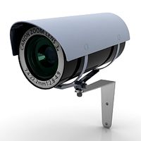
camera surveillance camera video camera
camera surveillance n090211 - 3d model (*.3ds) for interior 3d visualization.
archibase_planet
free
Camera
...hibase planet
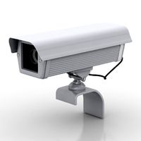
camera security camera video camera
camera security n210515 - 3d model (*.gsm+*.3ds) for exterior 3d visualization.
archibase_planet
free
Camera
...se planet
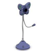
camera web camera webcam
camera butterfly usb pc camera n090713 - 3d model (*.gsm+*.3ds) for interior 3d visualization.
archibase_planet
free
Camera
...mera
archibase planet
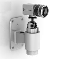
surveillance camera video camera camcorder
camera n011211 - 3d model (*.3ds) for exterior 3d visualization.
archibase_planet
free
Camera
...camera
archibase planet
camera digital camera
camera canon digital n041211 - 3d model (*.3ds) for interior 3d visualization.
archibase_planet
free
Camera
...camera
archibase planet
camera film camera phototechnique
camera n100214 - 3d model (*.gsm+*.3ds) for interior 3d visualization.
archibase_planet
free
Camera
...amera
archibase planet
camera video camera camcorder
camera video n070315 - 3d model (*.gsm+*.3ds) for interior 3d visualization.
archibase_planet
free
Camera
...rchibase planet
camera video camera camcorder
camera studio n101213 - 3d model (*.gsm+*.3ds+*.max) for interior 3d visualization.
archibase_planet
free
Camera
...ibase planet
digital camera camera phototechnique
camera canon ixus 400 n310311 - 3d model (*.3ds) for interior 3d visualization.
archibase_planet
free
Camera
...ase planet
photocamera video camera camera
camera sony t300 black n291010 - 3d model (*.gsm+*.3ds) for interior 3d visualization.