Thingiverse
Rotary Hydroponic Unit by 4ndy
by Thingiverse
Last crawled date: 2 years, 12 months ago
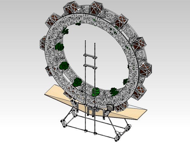
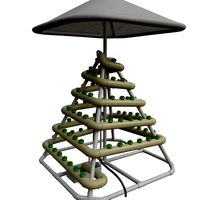
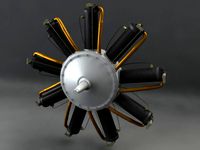
Who said we couldn't print useful things? Here's a flat-pack modular rotary hydroponic unit to be produced by most CNC tools.
My Blog Post about this here: http://engineeringourfreedom.blogspot.com/2011/05/do-cartwheels-feed-people.html
For working examples of such a system, see OmegaGarden.com RotoGro.com or H2ODynamic.com
Call it the ModRotoHydro, RapFarm, FeederBot, Farm@Home, or whatever else you like, I don't care, just help me build them and feed the world. ;D
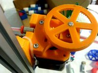
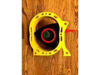
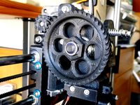
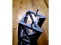
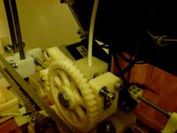
Some bits of the assembly are made from or based on standard mendel parts, such as the frame vertex and Prusa's Y-bar clamps. The current gear-tooth profile is based on http://www.thingiverse.com/thing:8077; I might try a version with an easier-to-print zigzag, though it may be less efficient.
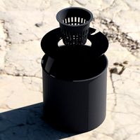
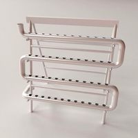
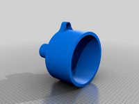
The cylinder has an outer diameter of 1 metre, ID of 80cm, and the trays are designed to hold 75mm/3" rockwool cubes, though it would be very easy to design alternate holders for smaller sizes.
Currently I have designed the system to use a gear ratio of 11/1056, i.e. 44 teeth on each of 24 segments, using a 3-3.6rpm synchronous motor pulled from the base of a broken halogen heater. If you want me to release alternative parts, e.g. with different numbers of teeth on the segment, just say so and I'll get on it for you.
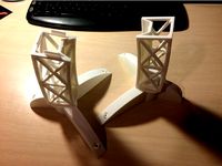
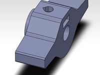
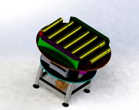
I have been designing the base-frame to try and use 1m lengths of studding with as little random waste as possible, but you could construct this at different sizes with odds and ends if you so wish. It doesn't make a difference so long as a tray and reservoir can fit under the cylinder.
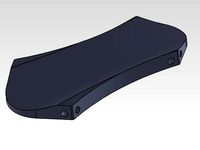
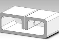
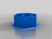
The tray support designed is now up. It uses 8mm studding to span the gap in the design, but I think you could possibly use some 6mm dowel, but don't take my word for it until you or I have done a stress calculation. I'm thinking of having it so you simply hang a polyethylene sheet across the gap in the base to make a sump for the nutrients. There needs to be a hole in the bottom to drain excess away into a reservoir though, and some kind of hose line up from the reservoir to pump it in.
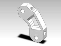
The weight-saving gaps have mostly been placed conservatively using intuition and best practice of avoiding sharp corners, but I have yet to do any FEA on the components to see if this can be improved for even more strength and less weight. However, I expect design 1.0 to work as it is with lightweight infill settings.
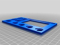
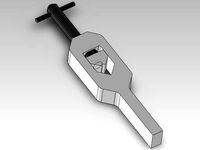
Any DXF files that end with a measurement are giving the reccomended thickness of sheet to cut the part out of, in order to fit within this design, however you may be able to change these around a bit and file holes down to fit.
Let me know if you want another file format. I added a DXF of the geared segment face on request, for anyone able to cut that profile halfway through a 10mm board. I promise I'll get round to drawing up a less-botched-together motor mounting part that follows some kind of one-size-fits-all geometric rule (eventually).
My Blog Post about this here: http://engineeringourfreedom.blogspot.com/2011/05/do-cartwheels-feed-people.html
For working examples of such a system, see OmegaGarden.com RotoGro.com or H2ODynamic.com
Call it the ModRotoHydro, RapFarm, FeederBot, Farm@Home, or whatever else you like, I don't care, just help me build them and feed the world. ;D
Some bits of the assembly are made from or based on standard mendel parts, such as the frame vertex and Prusa's Y-bar clamps. The current gear-tooth profile is based on http://www.thingiverse.com/thing:8077; I might try a version with an easier-to-print zigzag, though it may be less efficient.
The cylinder has an outer diameter of 1 metre, ID of 80cm, and the trays are designed to hold 75mm/3" rockwool cubes, though it would be very easy to design alternate holders for smaller sizes.
Currently I have designed the system to use a gear ratio of 11/1056, i.e. 44 teeth on each of 24 segments, using a 3-3.6rpm synchronous motor pulled from the base of a broken halogen heater. If you want me to release alternative parts, e.g. with different numbers of teeth on the segment, just say so and I'll get on it for you.
I have been designing the base-frame to try and use 1m lengths of studding with as little random waste as possible, but you could construct this at different sizes with odds and ends if you so wish. It doesn't make a difference so long as a tray and reservoir can fit under the cylinder.
The tray support designed is now up. It uses 8mm studding to span the gap in the design, but I think you could possibly use some 6mm dowel, but don't take my word for it until you or I have done a stress calculation. I'm thinking of having it so you simply hang a polyethylene sheet across the gap in the base to make a sump for the nutrients. There needs to be a hole in the bottom to drain excess away into a reservoir though, and some kind of hose line up from the reservoir to pump it in.
The weight-saving gaps have mostly been placed conservatively using intuition and best practice of avoiding sharp corners, but I have yet to do any FEA on the components to see if this can be improved for even more strength and less weight. However, I expect design 1.0 to work as it is with lightweight infill settings.
Any DXF files that end with a measurement are giving the reccomended thickness of sheet to cut the part out of, in order to fit within this design, however you may be able to change these around a bit and file holes down to fit.
Let me know if you want another file format. I added a DXF of the geared segment face on request, for anyone able to cut that profile halfway through a 10mm board. I promise I'll get round to drawing up a less-botched-together motor mounting part that follows some kind of one-size-fits-all geometric rule (eventually).
Similar models
thingiverse
free
Small gear for RepRapPro mini extruder by rogueqd
...al, which fits my motor shaft better. i can upload a same height version if needed.
https://github.com/reprappro/extruder-drive
thingiverse
free
better Gears for Wankel Rotary Engine (by ECU) by DocNo
... wankel rotary engine (by ecu) by docno
thingiverse
the original gear teeths are a bit to small, so i designed a different pair.
thingiverse
free
Prusa I3 Rework Herringbone Gears by majurca
...g values for the correct steps of the extruder feeding.
i also include the small 10-tooth gear in case someone wants to use it.
thingiverse
free
Led Bridge Lamp - bolted version by flash24
...inted on flashforge dreamer in pla, no supports, no raft.
first layer max. speed 10mm/s, 30% infill - standard print resolution.
thingiverse
free

Rotary Motion Kid Wind Adapter by Smythics
... can be used in place of the gears, but i need to improve the quality before these get posted. if you beat me to it, let me know!
thingiverse
free

Arduino UNO Breadboard Tray by electronron
...7
the rsdoc file contains a couple of items that i haven't printed but i left them in the file in case someone is interested.
thingiverse
free
Foot alternative to bridge lamp by Neukyhm
...o be screwed.
i know they don't look as good as opossums's designs, but as i said this is my first design with fusion360.
grabcad
free

Involute Flank Spur Gear
... a small gearbox using only this part.
you can use this freely. i would also love to see some comments from anyone who uses it.
thingiverse
free
Armada Card tray split into two parts by Artifixprime
...s.
note: i have not test printed this myself yet, so i can't be 100% how it will turn out.
the main tray works fine though :)
thingiverse
free

Capresso coffee maker replacement tray by LostBullet
...y machine the space for the tray seems not to be squared so i had to make it smaller to fit and then the cover did not fit right.
4Ndy
thingiverse
free
Bracer by 4ndy
...racer by 4ndy
thingiverse
a simple forearm-protector for archery.
intended for sporting use. none of that nasty agincourt stuff.
thingiverse
free
Tapping Wrench by 4ndy
...ole-tapping bits.
cheaper than any other wrench if you only want to get a couple of specifically-sized taps made from good steel.
thingiverse
free
Sandpaper Holder by 4ndy
... of sandpaper cut to 40mm wide by just over 200mm long, but with the files included it should be easy to re-design to your needs.
thingiverse
free
Slimline Lightweight Mendel Vertex by 4ndy
...by adapting a 3d model from marcus' thing.
the resulting part is 13mm thick and prints easily with no noticeable warp issues.
thingiverse
free
Filament Clip for Hinged Accessible Extruder by 4ndy
...olve the problem of filament pulling loose from the drive at extremes on the x-axis, while still keeping the drive it accessible.
thingiverse
free
Golf Tee (Flat-Pack) by 4ndy
...id.
you should be able to fit a few in a pocket quite easily and you could even use one section to repair divots and pitch marks.
thingiverse
free
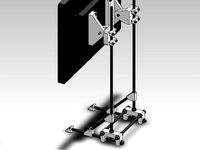
Adjustable Monitor Stand by 4ndy
...
i'm currently looking at a monitor on its built-in stand that ruins my posture when working, so i hope to make one of these.
thingiverse
free
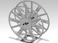
Modular Printable Spool by 4ndy
...with a horizontal axle. you should probably only use it on its side if you have glued/welded the segments together on the bottom.
thingiverse
free
Recycling Bin Key by 4ndy
... grip, a string hole easier to thread, less material, and extra strength at the base of the corner. also it looks way cooler. ^_^
thingiverse
free
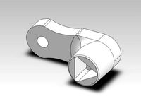
Thumb Crank for NEMA17 Motor Shaft by 4ndy
...t.
edit:
now includes an igs file, for extra compatibility. i encourage everyone to use transferrable formats like iges and step.
Hydroponic
turbosquid
$3
H2Gro Hydroponic Planter
...ty free 3d model h2gro hydroponic planter for download as stl on turbosquid: 3d models for games, architecture, videos. (1479664)
3d_export
$15
hydroponic stand
...e up render. - all parts and materials are logically named. other formats ================= - collada (.dae) - autodesk fbx - obj
3d_export
free

Zephyrus Hydroponic Air Purifier
...ze the air of any remaining microbes before it exits the front exhaust port. the entire system is controlled by a raspberry pi 4.
3d_export
$10

Glass Fishbowl Bowl Hydroponics Plant SET
...painter available for all software<br>ue4. ue5. blender. maya. 3d max. unity. c4d.<br>formats: .obj .gltf .fbx .blend
3d_export
$19

Glass hydroponic vase 01
... x 9.59" x 18.57"<br>- model parts: 6<br>- material count: 3<br>- xform: yes<br>- boxtrick: yes
3d_export
$19

Glass hydroponic vase 02
... x 4.44" x 16.26"<br>- model parts: 4<br>- material count: 3<br>- xform: yes<br>- boxtrick: yes
thingiverse
free
Hydroponic
...hydroponic
thingiverse
hydroponic
free3d
$10
HYDROPONIC SYSTEM
...hydroponic system
free3d
hydroponic system
thingiverse
free
hydroponic vase
...hydroponic vase
thingiverse
hydroponic pot
thingiverse
free
Hydroponic Pot
...hydroponic pot
thingiverse
pot for hydroponic growing
Rotary
3ddd
$1
Medical Rotary table
...medical rotary table
3ddd
медицинский стол
medical rotary table
turbosquid
$18

Codex Rotary
...squid
royalty free 3d model codex rotary for download as stl on turbosquid: 3d models for games, architecture, videos. (1439894)
turbosquid
$12

Rotary drill
...y free 3d model rotary drill for download as ma, obj, and fbx on turbosquid: 3d models for games, architecture, videos. (1394316)
3d_export
$6

The rotary module 3D Model
...the rotary module 3d model
3dexport
the rotary module
the rotary module 3d model armata2015 98145 3dexport
turbosquid
$40
Rotary Engine
... available on turbo squid, the world's leading provider of digital 3d models for visualization, films, television, and games.
turbosquid
$15

Rotary Phone
... available on turbo squid, the world's leading provider of digital 3d models for visualization, films, television, and games.
turbosquid
$10

ROTARY medal
... available on turbo squid, the world's leading provider of digital 3d models for visualization, films, television, and games.
turbosquid
$9
Rotary conveyor
...veyor for download as 3ds, max, ige, obj, fbx, stl, and sldas on turbosquid: 3d models for games, architecture, videos. (1300472)
3d_export
$5
Rotary Cylinder 3D Model
...rotary cylinder 3d model
3dexport
rotary cylinder pneumatic pressure torque
rotary cylinder 3d model fau 71217 3dexport
3ddd
$1

Medical Rotary Table M2
...medical rotary table m2
3ddd
медицинский , стол
medical rotary table m2
Unit
turbosquid
$4

UNIT
...unit
turbosquid
royalty free 3d model unit for download as on turbosquid: 3d models for games, architecture, videos. (1196686)
archibase_planet
free

Unit
...unit
archibase planet
desk board
entertainment unit 02 - 3d model (*.gsm+*.3ds) for interior 3d visualization.
3d_export
$15
control unit
...control unit
3dexport
control unit
3ddd
$1
bathroom unit
...bathroom unit
3ddd
bathroom unit
3ddd
$1

Crockery unit
...crockery unit
3ddd
сервант
crockery unit
3ddd
$1

Process unit
...process unit
3ddd
статуэтка
process unit
3d_export
$5

united nations
...united nations
3dexport
united nations-logo -cnc plant
turbosquid
$3

TV unit-1 / 2 unit
...-1 / 2 unit for download as 3ds, max, obj, fbx, dwg, and dae on turbosquid: 3d models for games, architecture, videos. (1207609)
3d_export
$5

tv unit
...tv unit
3dexport
the tv unit design simple design with texture for interior
3d_ocean
$5

Tv Unit
...gh quality apple tv unit. the model is made using 3ds max. hope you enjoy it and if you have any queries feel free to contact me.