Thingiverse
Rostock Prisma by JorgeRdgz
by Thingiverse
Last crawled date: 2 years, 12 months ago
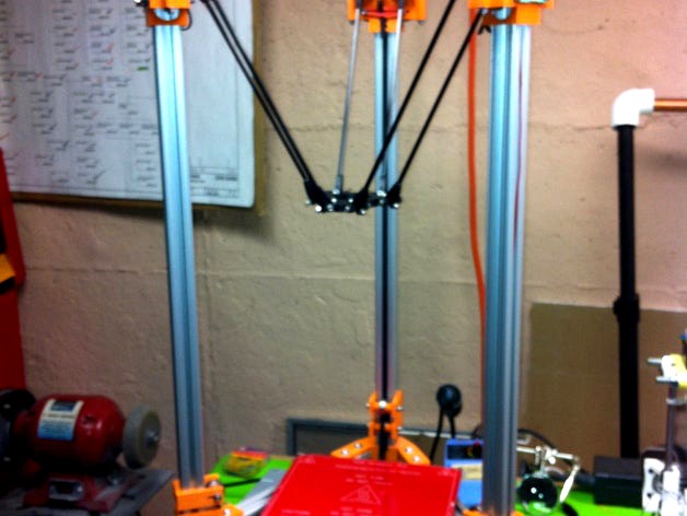
A derivative of Johann's Rostock but using 80/20 1010 T-Slotted aluminum instead of smooth SS rods. The extruded aluminum provide support for the prism structure.
Video: http://youtu.be/STc54aOQdK4
The goal for my derivative of the Johann’s Rostock was to build a simpler, lighter and more robust structure. I decided to use extruded aluminum since it’s quite strong, readily available, and relatively inexpensive. A piece of 80/20 10 SERIES 1010 1" X 1" T-SLOTTED EXTRUSION x 72" (1828.8mm) sells for $19 in Amazon.com. I was also inclined to use aluminum given that I have previous experience building and fabricating with this material (I built an all aluminum airplane in my garage).
Gone are all the wood parts, and the stainless steel rods. I kept the idea of using as many 3D printed parts as possible, since I had easy access to a friend’s Prusa Mendel printer. I am a software developer; hence it was easy for me to learn OpenSCAD to design my own parts. I tried to keep the number of new parts to a minimum and, if possible, reuse or make a derivative of the original Rostock parts.
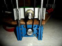
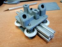
I studied the Rostock Max by SeeMeCNC, which I think it is awesome. I love the “Cheapskate†design so I tried to replicate it but instead of flat plates for the carriage I decided to modify Johann’s design to fit the profile of the 1010 and to accommodate four 608 bearings. After multiple iterations and head scratching sessions, I concluded that the best and easiest way to provide anti-backlash pressure between the bearings and the channel was to elongate the shaft holes and wrap a rubber band between the opposing M4 bolts serving as bearing shafts. It works beautifully.
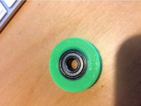
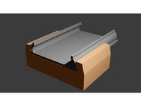
Another difference is in the track of the GT2 belt. On the Max, the belt in the back of the carriage tracks within the 1010 slot. On the other side of the carriage, the belt tracks a few millimeters parallel to the 1010 beam. On the PRISMA, the whole length of the belt, up and down segments, track within the inward facing slot of the 1010 beam. There’s a separation of approximately 3mm between the up and down moving segments of the belt. The separation is made possible by the double bearing idler design. One bearing pushes one segment of the belt inward into the channel while the other keeps the top belt tracking just above and flush with the edges of the channel. The only drawback to this approach was that it requires you to widen 1.5†(38mm) of the channel at the top and bottom to allow the 608 bearing to fit inside the slot in order to push the belt farther in. You can easily accomplish this task with a Dremel rotary tool, metal cutting tool, small sanding tool and a flat screwdriver.
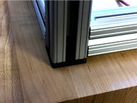
The three vertical sections of 1010 extrusion provide the support for the entire structure. I used my cheap compound miter saw with a $12 metal cutting blade to cut the extruded aluminum pieces. I cut the vertical pieces to 36†( 914.4mm). This translates to a maximum build height of roughly 13†(330mm). You can increase the build height by using longer verticals, however you need to keep in mind that you will need longer GT2 belts.
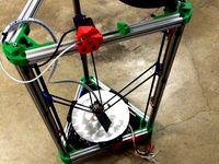
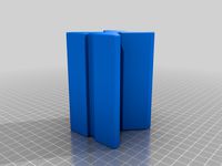
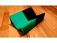
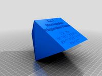
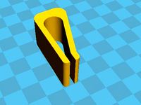
The horizontal aluminum pieces are sandwiched in between top and bottom plastic corner gussets at each end and secured with t-nuts. You can buy 80/20 t-nuts at $0.24 a piece or you can make your own by printing a bunch or tnut.stl copies and super gluing a regular 10-32 nut to the plastic. The final structure is a triangular/prism beam very straight, clean and sturdy.
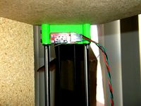
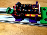
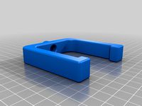
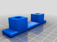
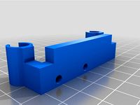
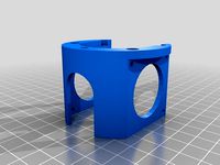
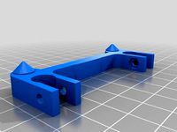
Lastly, all other parts hang from the aluminum extrusion; motor mounts, heated bed, idlers, electronics, power supply, etc. I design and printed special mounting clips that fit the 1010 profile.
Video: http://youtu.be/STc54aOQdK4
The goal for my derivative of the Johann’s Rostock was to build a simpler, lighter and more robust structure. I decided to use extruded aluminum since it’s quite strong, readily available, and relatively inexpensive. A piece of 80/20 10 SERIES 1010 1" X 1" T-SLOTTED EXTRUSION x 72" (1828.8mm) sells for $19 in Amazon.com. I was also inclined to use aluminum given that I have previous experience building and fabricating with this material (I built an all aluminum airplane in my garage).
Gone are all the wood parts, and the stainless steel rods. I kept the idea of using as many 3D printed parts as possible, since I had easy access to a friend’s Prusa Mendel printer. I am a software developer; hence it was easy for me to learn OpenSCAD to design my own parts. I tried to keep the number of new parts to a minimum and, if possible, reuse or make a derivative of the original Rostock parts.
I studied the Rostock Max by SeeMeCNC, which I think it is awesome. I love the “Cheapskate†design so I tried to replicate it but instead of flat plates for the carriage I decided to modify Johann’s design to fit the profile of the 1010 and to accommodate four 608 bearings. After multiple iterations and head scratching sessions, I concluded that the best and easiest way to provide anti-backlash pressure between the bearings and the channel was to elongate the shaft holes and wrap a rubber band between the opposing M4 bolts serving as bearing shafts. It works beautifully.
Another difference is in the track of the GT2 belt. On the Max, the belt in the back of the carriage tracks within the 1010 slot. On the other side of the carriage, the belt tracks a few millimeters parallel to the 1010 beam. On the PRISMA, the whole length of the belt, up and down segments, track within the inward facing slot of the 1010 beam. There’s a separation of approximately 3mm between the up and down moving segments of the belt. The separation is made possible by the double bearing idler design. One bearing pushes one segment of the belt inward into the channel while the other keeps the top belt tracking just above and flush with the edges of the channel. The only drawback to this approach was that it requires you to widen 1.5†(38mm) of the channel at the top and bottom to allow the 608 bearing to fit inside the slot in order to push the belt farther in. You can easily accomplish this task with a Dremel rotary tool, metal cutting tool, small sanding tool and a flat screwdriver.
The three vertical sections of 1010 extrusion provide the support for the entire structure. I used my cheap compound miter saw with a $12 metal cutting blade to cut the extruded aluminum pieces. I cut the vertical pieces to 36†( 914.4mm). This translates to a maximum build height of roughly 13†(330mm). You can increase the build height by using longer verticals, however you need to keep in mind that you will need longer GT2 belts.
The horizontal aluminum pieces are sandwiched in between top and bottom plastic corner gussets at each end and secured with t-nuts. You can buy 80/20 t-nuts at $0.24 a piece or you can make your own by printing a bunch or tnut.stl copies and super gluing a regular 10-32 nut to the plastic. The final structure is a triangular/prism beam very straight, clean and sturdy.
Lastly, all other parts hang from the aluminum extrusion; motor mounts, heated bed, idlers, electronics, power supply, etc. I design and printed special mounting clips that fit the 1010 profile.
Similar models
thingiverse
free
Delta Printer Frame Vertices (1x1") by bruckj
...he belts
3x m4 bolts (25mm long), nuts with nylon inserts, and multiple washers for the belt pulleys
sketchup files are included.
thingiverse
free

Glide Bearing, 80-20, 15 Series
...se
this is a bearing surface that fits between 2 parallel t-slot rails of the 80-20 structural aluminum, series 15 (1.50").
thingiverse
free
6mm T-Slot Wheel by scottpreston
...r etc. you can pick up these bearings and with the printed wheel you don't need to purchase special v-slot or special wheels.
thingiverse
free

Modified GregFrost's LM8UU 4 Bearing X Carriage by binaryconstruct
...re holes for mounting the extruder, round hole for nozzle
the belt groves are modified for gt2 but you can change it in the scad.
thingiverse
free
Rostock 608zz slot-on Belt Tensioner by PlannerProto
...ake it a step further by using the flanged f608zz to contain the belt and a nyloc nut, but so far the standard parts have worked.
thingiverse
free
U-Style LED Channel Clip by areHumansTuringComplete
...sing with 20mm aluminum extrusion.
clip extruded aluminum led channeling into part to retain led strips under aluminum extrusion.
thingiverse
free
Rostock mods for traxxas 5347, mechanical endstop mount, and jhead mount with aluminum keeper by jaykoehler
...earings to allow mounting above top board to make tensioning easy. add one at bottom for belt spreader.
feet (self explanatory)
thingiverse
free
Delta Printer Ramps Mount (1x1") by bruckj
...acket is a derivative of jwags55's raspberry pi mount (http://www.thingiverse.com/thing:513629).
sketchup files are included.
thingiverse
free
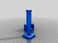
1x1 T-Slot Cap for Extruded Aluminum by afbrandx
...hingiverse
made this part as a foot for an 80/20 extruded aluminum box i made. the t-slot material is 10 series 1"x1".
thingiverse
free
G-slot carriage for delta printer by misan
...eel balls.
four 15mm m3 bolts
four v-shaped bearings.
epoxy
i got the extrusions from here: http://www.makergal.es/#!g-slot/c1ktz
Prisma
thingiverse
free
Prisma
...prisma
thingiverse
pla criart gruen
duese 210 grad
bett 60 grad
layer 0.2mm
speed 50
thingiverse
free
Prisma 100 Grad by Master_Q
...prisma 100 grad by master_q
thingiverse
prisma 100 grad 150 x 100 x 50 mm
if you like it ;)
thingiverse
free

3D Print PRISMA Chess by LupeToys
...int our mini version of prisma at home or through an online service using these free files and create a mini prisma set yourself!
thingiverse
free
Prisma Buegel
...prisma buegel
thingiverse
petg sainsmart schwarz
duese 235 grad
bett 80 grad
layerhoehe 0.2
speed 50
thingiverse
free

Red Alert 2 Prisma Tower by iSuat
...red alert 2 prisma tower by isuat
thingiverse
red alert 2 prisma tower
thingiverse
free

Foldable PRISMA Chess by LupeToys
...e pdf booklet. print the cut-out patterns for each of the 32 chess pieces at home and cut and paste them to make a 3d chess set!
thingiverse
free
KZ 7 überkapptes trigonales Prisma by SZS
...igte studierende im bereich der chemie und geometrie zu unterstützen.
chemie kennzahl kz 7
das modell ist in braille beschriftet.
thingiverse
free
KZ 9 dreifach überkapptes trigonales Prisma by SZS
...igte studierende im bereich der chemie und geometrie zu unterstützen.
chemie kennzahl kz9
das modell ist in braille beschriftet.
thingiverse
free

KZ 8 zweifach überkapptes trigonales Prisma by SZS
...igte studierende im bereich der chemie und geometrie zu unterstützen.
chemie kennzahl kz 8
das modell ist in braille beschriftet.
thingiverse
free
Soporte para Cuerda. Baúl Chevrolet Prisma LT by jositux
... en el baúl que puede servir para agregar accesorios.
en este caso un soporte para cuerdas, por ejemplo para ajustar una garrafa.
Rostock
thingiverse
free
Endstop for Rostock by Raz0neR
...endstop for rostock by raz0ner
thingiverse
endstop for rostock.
thingiverse
free

Rostock Cooling by nobicore
...rostock cooling by nobicore
thingiverse
rostock cooling
thingiverse
free
ROSTOCK PARTS by OC3D
...rostock parts by oc3d
thingiverse
parts for our modified rostock extruder assembly
thingiverse
free
Rostock squirrel fan by MarioPanic
...rostock squirrel fan by mariopanic
thingiverse
rostock squirrel fan
thingiverse
free
FC Hansa Rostock by ron86
...fc hansa rostock by ron86
thingiverse
fc hans rostock logo
thingiverse
free

rostock mini carriage by cjol
...rostock mini carriage by cjol
thingiverse
carriage for my rostock mini project
thingiverse
free

Rostock and Rostock Mini Dual Extruder Mount by westonshakespear
...ht.
sorry about the pictures, my filament jammed for part of the print and i am waiting for a new part to print a better version.
thingiverse
free
Rostock mini clip by Scott_Chen
...rostock mini clip by scott_chen
thingiverse
rostock mini clip for printer base glass
thingiverse
free
Rostock Board holder by drewan
...rostock board holder by drewan
thingiverse
this is a clip for using a rostock board as a print surface.
thingiverse
free
Rostock Fan Bracket by ImprisonedByTime
...rostock fan bracket by imprisonedbytime
thingiverse
this bracket is for a 40mm fan to attach to the rostock 3d printer