Thingiverse

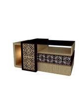
Root 3 CNC X Gantry Panels (Z Panels) by Menneset
by Thingiverse
Last crawled date: 3 years ago
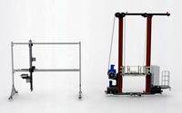
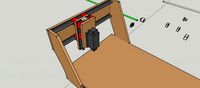
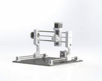
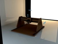
A set of printable X carriage (Z) panels for the Root3CNC by sailorpete.
For more details on the Root CNC project, look here.
Updated 8/1/17 - Upper_Front.stl and Z_Carriage.123dx, see Comments.
Final Assessment: After using the machine with the printed panels for a couple of weeks, I have concluded that they are just not stiff enough to do the job. I had to dial down both the speed and depth of cut. They work, and will get your machine running reliably, but it can easily be better. So, my suggestion is to use these to get your machine running long enough to cut some wooden panels, then replace them. - Thanks.
This model is based on the dual wood brace version of the X carriage with the universal panel option. I removed some unnecessary holes and clipped a bit off of the top of the panel to create my version of the front panel. You can if you prefer, print two back panel sets to get the original universal panel set.
I split both the front and back panels into two parts. The bottom half for both panels is identical, you will need to print one Z_Upper_Front, one Z_Upper_Back, and two Z_Lower. Or, print two Z_Upper_Back and omit the Z_Upper_Front. You will likely not need to print the Z_Bonding_Plate
To assemble you will need four smooth 3mm rods 60mm to 80mm long. The rods should fit snugly in the two holes found on the mating edge of each panel piece. Taping the rods into place with a small hammer may help. If you have to do more than just tap them, then they are too tight--forcing them will crack the plastic. It may be necessary to clear out the holes with a 3mm (or 1/8 inch) drill bit. I salvaged my 3mm rods from old CDROM and DVD drives.
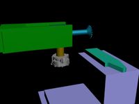
As you assemble the remainder on the CNC build, components will be bolted into place which will serve to hold the two halves of the panel securely together. At this time I have not assembled the front panel (I am still waiting on parts to arrive.) The intention is that the linear rails will secure the two halves of the panel. I have also provided a Z_Bonding_Plate model that may be used to strengthen the front panel. Again, I don't think that will be necessary.
One final note regarding the bonding plate only... when I model a screw hole with a nut trap that will be printed in an inverted position such as this piece has, I include a very thin layer across the screw hole at the top of the nut trap. This causes the slicer to treat the top of the nut trap as a bridge rather than an overhang.
For more details on the Root CNC project, look here.
Updated 8/1/17 - Upper_Front.stl and Z_Carriage.123dx, see Comments.
Final Assessment: After using the machine with the printed panels for a couple of weeks, I have concluded that they are just not stiff enough to do the job. I had to dial down both the speed and depth of cut. They work, and will get your machine running reliably, but it can easily be better. So, my suggestion is to use these to get your machine running long enough to cut some wooden panels, then replace them. - Thanks.
This model is based on the dual wood brace version of the X carriage with the universal panel option. I removed some unnecessary holes and clipped a bit off of the top of the panel to create my version of the front panel. You can if you prefer, print two back panel sets to get the original universal panel set.
I split both the front and back panels into two parts. The bottom half for both panels is identical, you will need to print one Z_Upper_Front, one Z_Upper_Back, and two Z_Lower. Or, print two Z_Upper_Back and omit the Z_Upper_Front. You will likely not need to print the Z_Bonding_Plate
To assemble you will need four smooth 3mm rods 60mm to 80mm long. The rods should fit snugly in the two holes found on the mating edge of each panel piece. Taping the rods into place with a small hammer may help. If you have to do more than just tap them, then they are too tight--forcing them will crack the plastic. It may be necessary to clear out the holes with a 3mm (or 1/8 inch) drill bit. I salvaged my 3mm rods from old CDROM and DVD drives.
As you assemble the remainder on the CNC build, components will be bolted into place which will serve to hold the two halves of the panel securely together. At this time I have not assembled the front panel (I am still waiting on parts to arrive.) The intention is that the linear rails will secure the two halves of the panel. I have also provided a Z_Bonding_Plate model that may be used to strengthen the front panel. Again, I don't think that will be necessary.
One final note regarding the bonding plate only... when I model a screw hole with a nut trap that will be printed in an inverted position such as this piece has, I include a very thin layer across the screw hole at the top of the nut trap. This causes the slicer to treat the top of the nut trap as a bridge rather than an overhang.
Similar models
thingiverse
free

Easier to Print Simonious' Supa-Flat X-Carriage by Ember
...w your slicer to generate any kind of bridging to print the hole on top of the larger nut trap, resulting in additional clean-up.
thingiverse
free

DVD laser carriage plotter parts by NilsR
...progress will be shared here. if you're building a similar project, you can use these parts as a base,...
thingiverse
free

Nut trap size test by Torby
...n, i'd give them credit.
oh. it came from github uploaded by stemer114 https://gist.github.com/stemer114/324c382a528d10b43759
thingiverse
free

Dremel CNC - Long Bed Printer Carriage by ConnorM2009
...co poly or abs may be better. it is still work in progress as need to work on limit switch bracketry and a bracket for a bl touch
thingiverse
free

MPCNC Corner Span Supports by Droneme
... .25in. dowel for alignment. after the threads are started you can pull the dowel out.
update-added a nut trap for 25mm conduit.
thingiverse
free

Topeak Quicktrack adapter for Stromer ST1X Racktime rack by pmeyer
...nd a nut below. the brace keeps the adapter from sliding off.
the quicktrack bag should then slide on and clip to the front bar.
thingiverse
free

Eclips3D modified A9,A10,A11,A12 Y axis rod holders by Av8er
... change to the rear holders is that i enlarged the rod hole to mach the front. if you use them you may not need to use any shims.
thingiverse
free

Bushing holder for 20mm hole-separation by misan
...the holder and the holder has nut-traps for m3 that with 12mm m3 screws will allow the part to be securely fixed to the carriage.
thingiverse
free

Rear Axle For 3mm threaded rod by jsloat31
...ors. i secured the wheels with the 3mm nuts that are used for the build. i did use the printed wheel lock nuts for added support.
thingiverse
free

ANET A8 Power Switch Box by MrWoo
...ay also want to resize the motor plate (the part that slides under the motor for stability) to fit your own personal installation
Menneset
thingiverse
free

DaVinci Lid Brace by Menneset
...ci lid brace by menneset
thingiverse
a simple, easy to make and use brace that will hold the lid of the davinci 3d printer open.
thingiverse
free

5mm LED clip by Menneset
...lds a 5mm led close to a surface. not the prettiest thing ever, but it is designed to be used for indirect light or backlighting.
thingiverse
free

Maze Box Redux keys by Menneset
...the maze box redux gift boxes.
the red one is maze 1, the easy one. perhaps i didn't fully think through the color choices...
thingiverse
free

Root 3 CNC NEMA 23 Spacer with Tab by Menneset
...oot 3 cnc that has an extra tab for adding a threaded rod cross piece to serve as a stiffener for the entire x carriage assembly.
thingiverse
free

Mega/Ramps Fan Mount by Menneset
...it has mounting holes for both 60mm fans and for 40mm fans. typically you will print two, but one alone could work in some cases.
thingiverse
free

Arduino Uno Model by Menneset
...be.
the dimensions came from this image by matthew beckler. thank you mr. beckler. another good source is, (as always,) adafruit.
thingiverse
free

T-Rex Tape Dispenser Revisited by Menneset
...ome on your desk and actually dispense a full roll of tape. it is especially awesome when printed with glow-in-the-dark filament!
thingiverse
free

Dremel Foot 45 degree hold by Menneset
...t; i am thinking that the head piece could have been bigger, i may come back and revisit that after i have used them for a while.
thingiverse
free

D&D Meeples Smaller Party by Menneset
...ee. basically i just used meshmixer to cut his tray of meeples into fourths and named them a,b,c,d. hope this helps someone else.
thingiverse
free

Light Ring for 65mm CNC Spindle by Menneset
...er you normally do should be just fine. i used e3000 to glue the led ring to the clamp, but again, use whatever you have on hand.
Gantry
turbosquid
$349
Gantry crane
...alty free 3d model gantry crane for download as ige and sldas on turbosquid: 3d models for games, architecture, videos. (1476278)
3d_export
free
firestone advertising gantry
...rs premises and<br>these advertisement gantries, were very popular in the 30-70's at grand prix races advertising tyres
turbosquid
$30
Derelict Launch Gantry
...alty free 3d model derelict launch gantry for download as fbx on turbosquid: 3d models for games, architecture, videos. (1669952)
turbosquid
$129
Gantry Crane RTG
...e 3d model gantry crane rtg for download as max, obj, and fbx on turbosquid: 3d models for games, architecture, videos. (1491933)
turbosquid
$120
Gantry stacker Assembly
...try stacker assembly for download as sldas, fbx, 3ds, and ige on turbosquid: 3d models for games, architecture, videos. (1648516)
turbosquid
$19

Train Signals Gantry
...l train signals gantry for download as 3ds, max, obj, and fbx on turbosquid: 3d models for games, architecture, videos. (1462242)
turbosquid
$5
STS Gantry Crane
... available on turbo squid, the world's leading provider of digital 3d models for visualization, films, television, and games.
turbosquid
$160

Bulk carrier with gantry crane
...carrier with gantry crane for download as lwo, obj, and blend on turbosquid: 3d models for games, architecture, videos. (1285258)
3d_export
$50
RMG Gantry Crane 3D Model
...t hoist rail rubber tyre tire rtg eot beam portal heigh tonne shipyard port
rmg gantry crane 3d model 5starsmodels 42860 3dexport
3d_export
$29
gantry crane
...istic model that will enhance the detail and realism of any of your rendering projects.<br>file formats: max, obj, fbx, 3ds
Root
3d_export
$5

root
...root
3dexport
a root from the tree
archive3d
free

Roots 3D Model
...ation ornament
roots of ginseng n010313 - 3d model (*.gsm+*.3ds) for interior 3d visualization.
3d_export
$5

yucca root
...yucca root
3dexport
3d_export
$5

lotus root
...lotus root
3dexport
3d_export
$5

turmeric root
...turmeric root
3dexport
3ddd
$1

CHAIR ROOT by Customform
...chair root by customform
3ddd
customform
chair root by customform.texture included.
turbosquid
$35

Turmeric Root
...oyalty free 3d model turmeric root for download as ma and obj on turbosquid: 3d models for games, architecture, videos. (1588571)
turbosquid
$17

Root on Stand
...yalty free 3d model root on stand for download as max and fbx on turbosquid: 3d models for games, architecture, videos. (1215521)
turbosquid
$2

Root Plant
...yalty free 3d model root plant for download as , fbx, and obj on turbosquid: 3d models for games, architecture, videos. (1608270)
turbosquid
$49

Root Lamp
...lty free 3d model root lamp for download as max, obj, and fbx on turbosquid: 3d models for games, architecture, videos. (1253803)
Cnc
3d_export
$35
Cnc
...cnc
3dexport
the cnc machine is unfinished
3d_export
$10
cnc router
...cnc router
3dexport
prototipe cnc router
3d_export
$10

cnc machine
...cnc machine
3dexport
cnc machine model with individual model files with assembly
3d_export
$5
Cnc 3D Model
...cnc 3d model
3dexport
cnc
cnc 3d model csiszar 61289 3dexport
turbosquid
$10

cnc bedroom
...osquid
royalty free 3d model cnc bedroom for download as max on turbosquid: 3d models for games, architecture, videos. (1494981)
turbosquid
$9
cnc(wood)
...rbosquid
royalty free 3d model cnc(wood) for download as max on turbosquid: 3d models for games, architecture, videos. (1189189)
turbosquid
$1

CNC Frame
...rbosquid
royalty free 3d model cnc frame for download as stl on turbosquid: 3d models for games, architecture, videos. (1371706)
turbosquid
free
cnc table
...rbosquid
royalty free 3d model cnc table for download as max on turbosquid: 3d models for games, architecture, videos. (1500926)
turbosquid
$30
CNC Lathe
...
royalty free 3d model cnc lathe for download as max and obj on turbosquid: 3d models for games, architecture, videos. (1284634)
turbosquid
$25
CNC Machine
...
royalty free 3d model cnc machine for download as ma and fbx on turbosquid: 3d models for games, architecture, videos. (1307199)
Z
3d_export
$5
nissan z
...nissan z
3dexport
nissan z
3ddd
$1

Vase Z
...vase z
3ddd
vase z
3ddd
$1
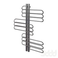
полотенцесушить Z
...полотенцесушить z
3ddd
полотенцесушитель
полотенцесушить z
design_connected
free
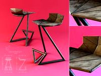
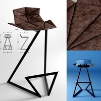
Z-Chair
...z-chair
designconnected
free 3d model of z-chair designed by karman, aleksei.
design_connected
$11

Z Lamp
...z lamp
designconnected
phillips z lamp computer generated 3d model. designed by kalff, louis.
3d_export
$5
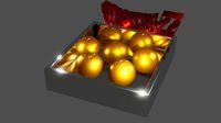
Dragon balls z
...dragon balls z
3dexport
dragon ball z
turbosquid
$20

Fighter Z
...
turbosquid
royalty free 3d model fighter z for download as on turbosquid: 3d models for games, architecture, videos. (1292563)
turbosquid
$9

Pen Z
...pen z
turbosquid
free 3d model pen z for download as obj on turbosquid: 3d models for games, architecture, videos. (1686775)
turbosquid
free
z chair
...z chair
turbosquid
free 3d model z chair for download as max on turbosquid: 3d models for games, architecture, videos. (1410230)
turbosquid
$5

Letter Z
...urbosquid
royalty free 3d model letter z for download as max on turbosquid: 3d models for games, architecture, videos. (1408540)
Panels
3d_export
$15

panel
...panel
3dexport
panel
archibase_planet
free

Panel
...panel
archibase planet
panel
panel - 3d model for interior 3d visualization.
3d_export
$5

panel
...panel
3dexport
panel with cones
3ddd
$1

Panels
...panels
3ddd
панель
panels
3d_export
$5

panel
...panel 3dexport panels grapes with...
archibase_planet
free

Panel
...panel
archibase planet
panel wainscot dado
play panel n050707 - 3d model for interior 3d visualization.
archibase_planet
free

Panel
...panel
archibase planet
lining panel facing material
panel 2 - 3d model (*.3ds) for interior 3d visualization.
archibase_planet
free

Panel
...panel
archibase planet
lining panel facing material
panel 1 - 3d model (*.gsm+*.3ds) for interior 3d visualization.
archibase_planet
free

Panel
...panel
archibase planet
keyboard patchboard finger-board
security panel - 3d model for interior 3d visualization.
turbosquid
$10

Panel
...l
turbosquid
royalty free 3d model panel for download as stl on turbosquid: 3d models for games, architecture, videos. (1387163)
3
turbosquid
$10
Mountain Bike 3 -3 of 3
...model mountain bike 3 (#3 of 3) for download as fbx and blend on turbosquid: 3d models for games, architecture, videos. (1438752)
turbosquid
$6

Rock 3-3
...urbosquid
royalty free 3d model rock 3-3 for download as obj on turbosquid: 3d models for games, architecture, videos. (1628065)
turbosquid
$29

Books 150 pieces 3-3-3
...books 150 pieces 3-3-3 for download as max, obj, fbx, and stl on turbosquid: 3d models for games, architecture, videos. (1384033)
turbosquid
$3

Genesis 3 Clothing 3
... available on turbo squid, the world's leading provider of digital 3d models for visualization, films, television, and games.
3d_export
$5
hinge 3
...hinge 3
3dexport
hinge 3
3ddd
$1

Розетка 3
...розетка 3
3ddd
розетка
розетка 3
turbosquid
$50

is-3
... available on turbo squid, the world's leading provider of digital 3d models for visualization, films, television, and games.
turbosquid
$10
Mountain Bike 3 -2 of 3
...model mountain bike 3 (#2 of 3) for download as fbx and blend on turbosquid: 3d models for games, architecture, videos. (1438750)
turbosquid
$10
Mountain Bike 1 -3 of 3
...model mountain bike 1 (#3 of 3) for download as fbx and blend on turbosquid: 3d models for games, architecture, videos. (1438743)
3d_export
$5

3 CATS
...3 cats
3dexport
3 cats pen holder