GrabCAD

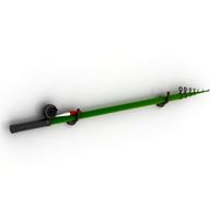
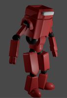
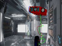
Rod Holder concept4: The Robot
by GrabCAD
Last crawled date: 1 year, 11 months ago
Design philosophy: Do away with knob interfaces at all cost yet maintain the same dexterity, degrees of freedom, strength and aesthetic appeal as with as design using knobs.
Materials: Wood, recycled and non recycled rubber, plastics possibly recycled, aluminum. Ideally, the materials would be used as shown with the tubing and mechanicals in aluminum however I designed it robust enough so that every part (except rubber components and springs) could possibly be 3D printed. Some rough estimates for 3D printed parts can be found @ http://shpws.me/pv6H, http://shpws.me/puAX, http://shpws.me/pv6P
Budget spectrum: midrange. Although seemingly complex, most of the mechanical components can be CNC’d from aluminum in mass quantity, 3D printed or injection molded for reasonable cost.
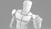
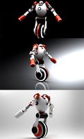
So in this design, although seemingly more complex in construction than previous concepts, the main idea was to do away with manual adjusted knobs of any kind and provide the user with the benefit of adjustability in its’ bare form. With the robot, the user doesn’t have to be aware that he is making a complex set of adjustments to his/her rod just to get the desired angle, they simply need to point the rod in the direction they want it and it stays there for good, locked in position.
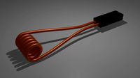
For this design, I was inspired by the way motor cycle transmission gears work to lock into each other, more specifically, the kick start mechanism. So I developed a version that could be used in this application. Two interlocking gears mesh until pulled apart, simply, a spring is used to supply the return force to re-mesh the notch faced gears. My design allows for 18 different positions of adjustability around 360 degree, with only .13” of distance required to unlock the notched faces to allow for rotation. The notched plates allow for lateral pivot movement (rotation on horizontal plane, **well slightly tilted but might rework that) and another to allow for pivot of the holster up and down (rotation on vertical plane). All the user needs to do is to push down .13” to disengage the notched plates and simply rotate into position, the heavy duty return spring reengages the notch plates and everything is held in place tightly, no slipping, no walking, where you place it is where it stays, all without the need to adjust any knobs or having to worry about them loosening. The same procedure is used to pivot the rod up and down on the verticle, simply hold the base of the holder and pull out .13”, pivot and let it find it’s position to snap back into place. All set.
With regards to the boat clamping method, again the focus was for simplicity. Two padded claws are simply rotated about 27 degrees and the pads slide under the bottom boat ledge to secure everything snuggly. The claws are attached by 2 screws and custom made slider plates, the screws are tightened snuggly just enough so the claws can be rotated into the open and closed position. The only issue that could arise is that the rotational forces of the rod and rod holder slowly work to reopen the clamp, prototype testing would need to be done but if this were the case, simply added a small knob to additionally tighten the claws should suffice.
Please check out the attached .pdf with the complete list of parts required and the included BOM.excel, it’s a work in progress but I have received estimates for injection molding some parts. Trapper, don’t let the complexity intimidate you, it’s actually quite a simple design. The idea would be to have most of the mechanicals CNC’d in aluminum, the plastics and rubber, injected molded and the wood parts CNC’d. My extremely rough estimate would put the unit cost at possibly 50-100$ with possibly, but hopefully under 50$US per unit with 50,000-80,000$ in upfront tooling costs, but the BOM needs to be fully completed, just a super ball park estimate >>will update BOM as I estimates come in.
Materials: Wood, recycled and non recycled rubber, plastics possibly recycled, aluminum. Ideally, the materials would be used as shown with the tubing and mechanicals in aluminum however I designed it robust enough so that every part (except rubber components and springs) could possibly be 3D printed. Some rough estimates for 3D printed parts can be found @ http://shpws.me/pv6H, http://shpws.me/puAX, http://shpws.me/pv6P
Budget spectrum: midrange. Although seemingly complex, most of the mechanical components can be CNC’d from aluminum in mass quantity, 3D printed or injection molded for reasonable cost.
So in this design, although seemingly more complex in construction than previous concepts, the main idea was to do away with manual adjusted knobs of any kind and provide the user with the benefit of adjustability in its’ bare form. With the robot, the user doesn’t have to be aware that he is making a complex set of adjustments to his/her rod just to get the desired angle, they simply need to point the rod in the direction they want it and it stays there for good, locked in position.
For this design, I was inspired by the way motor cycle transmission gears work to lock into each other, more specifically, the kick start mechanism. So I developed a version that could be used in this application. Two interlocking gears mesh until pulled apart, simply, a spring is used to supply the return force to re-mesh the notch faced gears. My design allows for 18 different positions of adjustability around 360 degree, with only .13” of distance required to unlock the notched faces to allow for rotation. The notched plates allow for lateral pivot movement (rotation on horizontal plane, **well slightly tilted but might rework that) and another to allow for pivot of the holster up and down (rotation on vertical plane). All the user needs to do is to push down .13” to disengage the notched plates and simply rotate into position, the heavy duty return spring reengages the notch plates and everything is held in place tightly, no slipping, no walking, where you place it is where it stays, all without the need to adjust any knobs or having to worry about them loosening. The same procedure is used to pivot the rod up and down on the verticle, simply hold the base of the holder and pull out .13”, pivot and let it find it’s position to snap back into place. All set.
With regards to the boat clamping method, again the focus was for simplicity. Two padded claws are simply rotated about 27 degrees and the pads slide under the bottom boat ledge to secure everything snuggly. The claws are attached by 2 screws and custom made slider plates, the screws are tightened snuggly just enough so the claws can be rotated into the open and closed position. The only issue that could arise is that the rotational forces of the rod and rod holder slowly work to reopen the clamp, prototype testing would need to be done but if this were the case, simply added a small knob to additionally tighten the claws should suffice.
Please check out the attached .pdf with the complete list of parts required and the included BOM.excel, it’s a work in progress but I have received estimates for injection molding some parts. Trapper, don’t let the complexity intimidate you, it’s actually quite a simple design. The idea would be to have most of the mechanicals CNC’d in aluminum, the plastics and rubber, injected molded and the wood parts CNC’d. My extremely rough estimate would put the unit cost at possibly 50-100$ with possibly, but hopefully under 50$US per unit with 50,000-80,000$ in upfront tooling costs, but the BOM needs to be fully completed, just a super ball park estimate >>will update BOM as I estimates come in.
Similar models
grabcad
free

Rod Holder Challenge
...that was structurally sound while maintaining the aesthetic of similar pieces of equipment that can be found for fishing,...
grabcad
free

Injection Mold - Knob .
...injection mold - knob .
grabcad
plastic injection mold for a knob .
2 plate mold with 04 cavity's .
grabcad
free

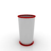
Estimate for mold injection of a coaster.
...estimate for mold injection of a coaster.
grabcad
estimate for mold.
grabcad
free

Saare Yachts Molded Vent
...s, will be a low cost alternative.
this design offers a 30 degree rotation of the knob from open to close in 5 degree increments.
grabcad
free

Rubber injection mold
...rubber injection mold
grabcad
rubber injection mold
grabcad
free

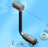
Adjustable stroke mechanism
...
grabcad
rotation of the input crank reciprocates the piston. stroke can be adjusted by varying the position of the pivot point.
thingiverse
free

Guitar Pick and Injection Mold by bbo
...ss. not a guitar pick.https://www.youtube.com/watch?v=cqgw3y-tw1w
casting link here:https://www.youtube.com/watch?v=falqah1v5_s
grabcad
free

Injection molding of rubber o-rings
...injection molding of rubber o-rings
grabcad
injection mold rubber o-rings
thingiverse
free

Prusa Z axis zero-point adjuster by RobPRINT
...ore problems with z axis adjusting!
with this thing you simply rotate the knob to precisely adjust the zero position on z axis :)
grabcad
free

Trapper Challenge
...e. the main body of the rod holder could be die cut directly from the recycled tires or die cut from crumb-rubber/urethane sheet.
Concept4
grabcad
free

BLADE COWLING ASSY- CONCEPT4
...ve bi-directional gearbox segment2 allowing for 45 degrees of pivot for changing the angle of the contra-rotating blade assembly.
grabcad
free

URBEE insignia challenge: Concept4
...-logo-3-1
https://grabcad.com/library/urbee-design-challenge-concept-2-1
https://grabcad.com/library/urbee-insignia-challenge-1
grabcad
free

URBEE insignia challenge: Concept5
...preference. my other 4 entries can be found here: https://grabcad.com/library/urbee-insignia-challenge-concept41 https://grabcad.com/library/urbee-design-challenge-concept-logo-3-1 https://grabcad.com/library/urbee-design-challenge-concept-2-1 https://grabcad.com/library/urbee-insignia-challenge-1 model references for rendering:...
3dwarehouse
free
concept4
...concept4
3dwarehouse
concept4
Rod
archibase_planet
free
Rod
...rod
archibase planet
shank rod
so rod - 3d model (*.gsm+*.3ds) for interior 3d visualization.
archibase_planet
free
Spinning rod
...g rod
archibase planet
spinning rod spinning rod fishing-rod
spinning rod - 3d model (*.gsm+*.3ds) for interior 3d visualization.
3d_export
$5
rod handle
...rod handle
3dexport
rod handle
3ddd
$1
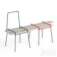
bench with rods
...bench with rods
3ddd
скамейка
bench with rods
3ddd
$1
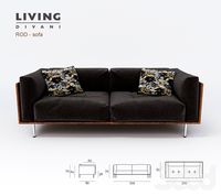
диван ROD
...диван rod
3ddd
rod , living divani
http://www.livingdivani.it/
3ddd
$1
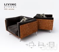
кресло ROD
...кресло rod
3ddd
rod , living divani
http://www.livingdivani.it/
design_connected
$18
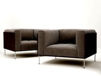
Rod Armchair
...rod armchair
designconnected
living divani rod armchair computer generated 3d model. designed by lissoni, piero.
archive3d
free

Rod 3D Model
...rod 3d model
archive3d
shank rod
so rod - 3d model (*.gsm+*.3ds) for interior 3d visualization.
turbosquid
$15

Fishing rod
...urbosquid
royalty free 3d model fishing rod for download as on turbosquid: 3d models for games, architecture, videos. (1684756)
turbosquid
free
Heating Rod
...rod
turbosquid
free 3d model heating rod for download as obj on turbosquid: 3d models for games, architecture, videos. (1482690)
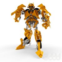
Robot
3d_ocean
$20

Robot
...robot
3docean
character metal robot robot robotic white
robot model for 3dsmax 2009 and greater
3d_ocean
$45
Robot
...robot
3docean
fighing machine robot
a fighting robot from the scrapyard.
3d_ocean
$18
Robot
...robot
3docean
machin robot science fiction
high poly robot.
3d_export
$7
Robot
...robot
3dexport
robot
3d_export
$5
robot
...robot
3dexport
robot
3d_export
free

Robot
...robot
3dexport
robot
turbosquid
$10

Robot/ Alien Robot
...
royalty free 3d model robot/ alien robot for download as max on turbosquid: 3d models for games, architecture, videos. (1442828)
3d_export
$5

robot
...robot
3dexport
robot in blender
3ddd
$1
robot
...robot
3ddd
робот
robot
3ddd
$1

Robot
...robot
3ddd
робот
robot
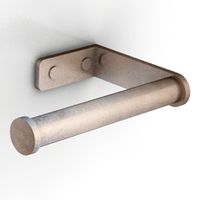
Holder
archibase_planet
free

Holder
...holder
archibase planet
holder toilet paper holder
holder paper n070712 - 3d model (*.gsm+*.3ds) for interior 3d visualization.
archibase_planet
free
Holder
...e planet
holder rack toilet paper holder
holder toilet roll n240715 - 3d model (*.gsm+*.3ds+*.max) for interior 3d visualization.
archibase_planet
free
Holder
...holder
archibase planet
pen holder support prop
pen holder - 3d model for interior 3d visualization.
archibase_planet
free
Holder
...holder
archibase planet
pole post holder
сhurch cross pole holder - 3d model for interior 3d visualization.
archibase_planet
free
Holder
...holder
archibase planet
holder bathroom ware
shower holder - 3d model (*.gsm+*.3ds) for interior 3d visualization.
archibase_planet
free
Holder
...oilet paper holder
holder paper devon&devon; time black n241113 - 3d model (*.gsm+*.3ds+*.max) for interior 3d visualization.
archibase_planet
free
Holder
...holder
archibase planet
holder hanger hanger for towel
holder 7 - 3d model (*.gsm+*.3ds) for interior 3d visualization.
archibase_planet
free
Holder
...holder
archibase planet
holder hanger hanger for towel
holder 3 - 3d model (*.gsm+*.3ds) for interior 3d visualization.
archibase_planet
free
Holder
...holder
archibase planet
holder towel rack towel-horse
holder - 3d model (*.gsm+*.3ds) for interior 3d visualization.
archibase_planet
free
Holder
...lder
archibase planet
holder hanger hanger for towel
holder towel n250912 - 3d model (*.gsm+*.3ds) for interior 3d visualization.