Thingiverse
Robotic Arm by BeatrizST
by Thingiverse
Last crawled date: 3 years, 3 months ago
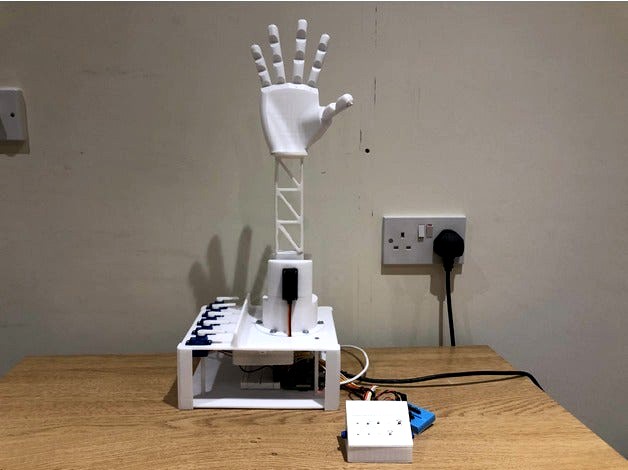
After the closure of schools in March 2020 I decided to embark on a robotics project. I am fascinated by the field of robotics and so I was eager to experiment with it myself. So I set out to build a 3D printed robotic arm. I designed the arm in Fusion360 and 3D printed it with an Anycubic i3 Mega. The arm is programmed on Python and works using a Raspberry Pi with standard and micro-servos to control the joint movements.
By no means is this a perfect robotic arm. It does have it's many flaws but it ultimately works and makes for a really fun project. I welcome any improvements you may think are appropriate so let me know if you have any suggestions.
More information on how this project came together can be found on my website. https://beatrizstortosa.wixsite.com/myprojects
Feel free to contact me if you have any questions.
----------------------------------------------- MATERIALS ------------------------------------------------------
Raspberry Pi Model 3 B (This is what I used but really any micro-controller can work)
Breadboard
Mini-Breadboard
10K Resistors x10 (One for each button)
Cables (Male-Female and Male-Male)
Buttons x10 (6x6mm)
Potentiometers x2 (I didn't end up using these but the 'Control Panel' is designed to hold one on either side. These can be used to control the elbow joint with more precision)
Standard Servos x2 (Only one servo is necessary for the joint but I designed the arm to hold two just in case one wasn't enough to lift the arm and for lifting heavy loads)
Micro Servos x5
DC Barrel Socket to Screw Terminals (To provide power to the servos via a 12W wall adapter)
Nylon Paracord (2-3mm thick)
Fishing Line
------------------------------------------------ PRINTING --------------------------------------------------------
Printer: Anycubic i3 Mega
Filament: PLA
Resolution: 0.1-0.3mm (I used 0.1mm)
Infill: 15-20%
ArmTop.stl - The design requires support everywhere but with a lot of patience these can be removed.
ControlPanelTop.stl - Once printed use a piece of nail file to file down the inside of the holes for the buttons. This will ensure they fit tightly with no glue required so it's easier to replace faulty buttons.
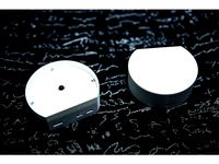
MicroServoHornExtension.stl - Print one for each micro servo and glue them on. The fingers will be able to flex more by using these horn extensions.
Fingers and Hand - Designed by grossrc. Works great with my design.
------------------------------------------------ BUILDING --------------------------------------------------------
Hand:
To build the hand, simply use pieces of flexible nylon fed through the fingers and tied at the back of the hand. Then, feed large pieces of fishing wire through the fingers and out of the bottom of the hand, these will then go down the arm and to the micro servos.
Servos:
Installation of the servos (both standard and micro) requires you to disassemble them, fit them in, and them assemble them once again. This is easy to do, just unscrew the four screws at the bottom and separate the bottom part of the servo. Try not to separate the top part of the servo since that's where all the gears are and they could come lose.
Arm:
To connect the arm to the arm base I used hot glue. Provides really strong adhesion and if you make a mistake it can be removed.
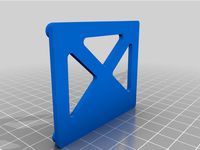
The pillar supports are held on with nails at the top and bottom, fitted in tightly. However, you could probably do without these supports as the corner supports already provide a lot of structural integrity. The corner supports are super glued to the top and bottom plates. It's best to glue this on once the electronics and servos are in place to avoid having to mess around with the cables in the small space but if you need to, tweezers come in very handy.
Pi and Breadboard:
The raspberry pi is just held on with four screws and the breadboard has an adhesive on the bottom which I stuck to the bottom plate.
Cable Box:
The cable box holds all of the cables that go from the servos to the pi. This keeps everything much more organised on the outside but makes it a little difficult to replace servos. So try not to fry your servos like I did with uncontrolled power surges. To attach it I was initially going to screw the cable box to the top plate but I couldn't find any screws that would hold on tightly enough so I just added some hot glue along the outside perimeter.
Control Panel:
The control panel can be pretty challenging to put together. It's not strictly necessary for this project but I wanted to make the arm a bit more interactive. Each button has a 10K ohm resistor soldered on. To the other end of the resistor I soldered on a cable that then leads to the mini breadboard. To another leg of the button I soldered the signal cable that also grounds the buttons so there's no need for an extra ground cable. When soldered, make sure you insulate every bit of exposed wire with electrical tape. If any of those exposed wires touch each other, the control panel won't work. When you've soldered everything together you can push the buttons into place and feed the cables through the back of the panel. I also added two potentiometers to the control panel with one 5V wire, one ground and one signal. I didn't end up using the potentiometes as I realised I need an analogue to digital converter which I didn't have but these could be used to control the elbow joint of the arm with precision.
Power:
To power all of this I used a 5W wall adapter going to the raspberry pi through the micro USB port and a separate 12W wall adapter going to the bread board that distributes the power to all of the servos. This is the best power supply arrangement that I could come up with but let me know if you can think of a better way. Do not try to power all of the servos through the raspberry pi, it's best to power them externally.
If requested I can add instructions on how to set up the electronics and add the code I used.
By no means is this a perfect robotic arm. It does have it's many flaws but it ultimately works and makes for a really fun project. I welcome any improvements you may think are appropriate so let me know if you have any suggestions.
More information on how this project came together can be found on my website. https://beatrizstortosa.wixsite.com/myprojects
Feel free to contact me if you have any questions.
----------------------------------------------- MATERIALS ------------------------------------------------------
Raspberry Pi Model 3 B (This is what I used but really any micro-controller can work)
Breadboard
Mini-Breadboard
10K Resistors x10 (One for each button)
Cables (Male-Female and Male-Male)
Buttons x10 (6x6mm)
Potentiometers x2 (I didn't end up using these but the 'Control Panel' is designed to hold one on either side. These can be used to control the elbow joint with more precision)
Standard Servos x2 (Only one servo is necessary for the joint but I designed the arm to hold two just in case one wasn't enough to lift the arm and for lifting heavy loads)
Micro Servos x5
DC Barrel Socket to Screw Terminals (To provide power to the servos via a 12W wall adapter)
Nylon Paracord (2-3mm thick)
Fishing Line
------------------------------------------------ PRINTING --------------------------------------------------------
Printer: Anycubic i3 Mega
Filament: PLA
Resolution: 0.1-0.3mm (I used 0.1mm)
Infill: 15-20%
ArmTop.stl - The design requires support everywhere but with a lot of patience these can be removed.
ControlPanelTop.stl - Once printed use a piece of nail file to file down the inside of the holes for the buttons. This will ensure they fit tightly with no glue required so it's easier to replace faulty buttons.
MicroServoHornExtension.stl - Print one for each micro servo and glue them on. The fingers will be able to flex more by using these horn extensions.
Fingers and Hand - Designed by grossrc. Works great with my design.
------------------------------------------------ BUILDING --------------------------------------------------------
Hand:
To build the hand, simply use pieces of flexible nylon fed through the fingers and tied at the back of the hand. Then, feed large pieces of fishing wire through the fingers and out of the bottom of the hand, these will then go down the arm and to the micro servos.
Servos:
Installation of the servos (both standard and micro) requires you to disassemble them, fit them in, and them assemble them once again. This is easy to do, just unscrew the four screws at the bottom and separate the bottom part of the servo. Try not to separate the top part of the servo since that's where all the gears are and they could come lose.
Arm:
To connect the arm to the arm base I used hot glue. Provides really strong adhesion and if you make a mistake it can be removed.
The pillar supports are held on with nails at the top and bottom, fitted in tightly. However, you could probably do without these supports as the corner supports already provide a lot of structural integrity. The corner supports are super glued to the top and bottom plates. It's best to glue this on once the electronics and servos are in place to avoid having to mess around with the cables in the small space but if you need to, tweezers come in very handy.
Pi and Breadboard:
The raspberry pi is just held on with four screws and the breadboard has an adhesive on the bottom which I stuck to the bottom plate.
Cable Box:
The cable box holds all of the cables that go from the servos to the pi. This keeps everything much more organised on the outside but makes it a little difficult to replace servos. So try not to fry your servos like I did with uncontrolled power surges. To attach it I was initially going to screw the cable box to the top plate but I couldn't find any screws that would hold on tightly enough so I just added some hot glue along the outside perimeter.
Control Panel:
The control panel can be pretty challenging to put together. It's not strictly necessary for this project but I wanted to make the arm a bit more interactive. Each button has a 10K ohm resistor soldered on. To the other end of the resistor I soldered on a cable that then leads to the mini breadboard. To another leg of the button I soldered the signal cable that also grounds the buttons so there's no need for an extra ground cable. When soldered, make sure you insulate every bit of exposed wire with electrical tape. If any of those exposed wires touch each other, the control panel won't work. When you've soldered everything together you can push the buttons into place and feed the cables through the back of the panel. I also added two potentiometers to the control panel with one 5V wire, one ground and one signal. I didn't end up using the potentiometes as I realised I need an analogue to digital converter which I didn't have but these could be used to control the elbow joint of the arm with precision.
Power:
To power all of this I used a 5W wall adapter going to the raspberry pi through the micro USB port and a separate 12W wall adapter going to the bread board that distributes the power to all of the servos. This is the best power supply arrangement that I could come up with but let me know if you can think of a better way. Do not try to power all of the servos through the raspberry pi, it's best to power them externally.
If requested I can add instructions on how to set up the electronics and add the code I used.
Similar models
thingiverse
free

R2D2 Servo Controller by JellyBitz
...ead board via the relay
connect all servos power cables to the breadboard.
the you can turn power offand on to them via the relay
grabcad
free

Humanoid Robot Hand
... by the length of the cable. this study resulted a robot hand that can perform to mimicking through human hand movement properly.
thingiverse
free
Spot Micro Plain Plate and Rpi and Servo Board Mounts by mike4192
... raspberry pi 3 and a pca9685 servo control board. small wood screws can be used to securely attach those boards to these plates.
thingiverse
free

Robotic hand servo powered by Hatsyflatsy
....thingiverse.com/thing:2727176
the finger parts from that design are compatible with this one. less parts and easier to assemble.
thingiverse
free

Mojo Raspberry Pi Zero W portable music streamer player by rumina
... port if the power switch is off or (better) the battery is secured with a additional diode, danger of fire due battery overload.
cults
free

Wireless Button Presser
...penings). screw the raspberry pi onto the bottom with four screws. after ensuring that everything works, screw on the lid. done!
thingiverse
free
Wireless Button Presser by Graystone
...openings). screw the raspberry pi onto the bottom with four screws. after ensuring that everything works, screw on the lid. done!
thingiverse
free

Raspberry Pi model B robot chassis by topshed
...ed by a phone power bank. slots are included in the chassis to house both of these. example worksheets and code can be found here
thingiverse
free

EleksMaker EleksLaser Pimoroni Pibow mount
...without the controller booted, the laser only partially fires, similar to a test...
thingiverse
free

CR-10 Raspberry Pi Zero W Mount by sfandersen
...uts to mount the pi to the print.
i use cura to send prints directly to octoprint on the pi zero. it is a power fill combination.

Robotic
3d_ocean
$20
Robot
...robot 3docean character metal robot robot robotic white robot model for 3dsmax 2009 and...
3d_ocean
$45
Robot
...robot
3docean
fighing machine robot
a fighting robot from the scrapyard.
3d_ocean
$18
Robot
...robot
3docean
machin robot science fiction
high poly robot.
3d_export
$7
Robot
...robot
3dexport
robot
3d_export
$5
robot
...robot
3dexport
robot
3d_export
free
Robot
...robot
3dexport
robot
turbosquid
$10
Robot/ Alien Robot
...
royalty free 3d model robot/ alien robot for download as max on turbosquid: 3d models for games, architecture, videos. (1442828)
3d_export
$5

robot
...robot
3dexport
robot in blender
3ddd
$1
robot
...robot
3ddd
робот
robot
3ddd
$1

Robot
...robot
3ddd
робот
robot
Arm
archibase_planet
free
Arm
...ase planet
arm hand right hand skeleton
arm human skeleton right arm n030515 - 3d model (*.gsm+*.3ds+*.max) for 3d visualization.
3ddd
$1

arm chair
...arm chair
3ddd
arm chair , пуф
arm chair
turbosquid
$5
arm
...arm
turbosquid
royalty free 3d model arm for download as obj on turbosquid: 3d models for games, architecture, videos. (1306158)
turbosquid
free
Arm
...arm
turbosquid
free 3d model arm for download as obj and fbx on turbosquid: 3d models for games, architecture, videos. (1346955)
turbosquid
$29
Arm
...osquid
royalty free 3d model arm for download as obj and fbx on turbosquid: 3d models for games, architecture, videos. (1382436)
3d_export
$5

coat of arms
...coat of arms
3dexport
coat of arms
3ddd
$1
ARM SOFA
...arm sofa
3ddd
arm sofa
3ddd
$1

Arm chair
...arm chair
3ddd
arm chair
3ddd
$1

Arm chair
...arm chair
3ddd
угловое
arm chair
3ddd
$1
ARM CHAIR
...arm chair
3ddd
arm chair clothes