Thingiverse
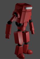
Robot Power Supply by NirDobovizki
by Thingiverse
Last crawled date: 2 years, 12 months ago
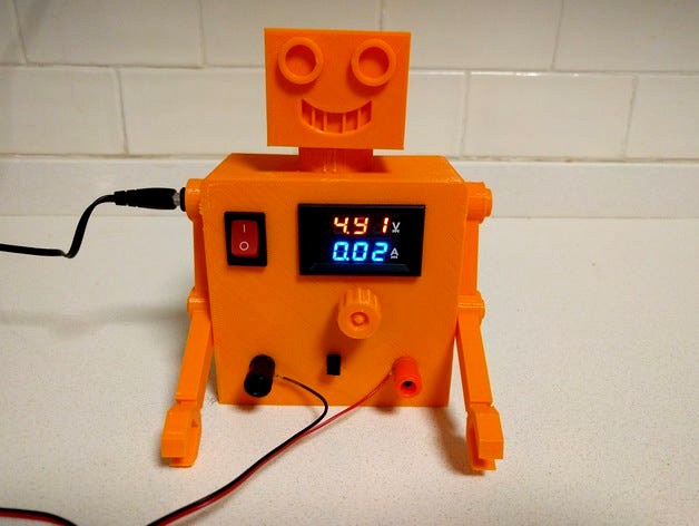
Without a doubt this is the most useful robot I designed so far.
This is basically an old 12v wall-wart I found in my drawer, an adjustable buck convertor and a volt/amper meter - together they become a very usable power supply for my crazy electronic projects.
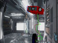
This adjustable power supply has 2 banana terminals (one +, one -), 4 connectors for jumper wires (2 +, 2 -) an ampermeter and a voltmeter.
Read the instruction below carefully, assembling this is a bit tricky - the know is very hard to connect after the buck converter in already in it's place.
Designed with SketchUp, fixed with Microsoft 3D Builder, sliced with Cura and printed in PLA on my Robo3D R1+
Parts:
Some kind of power supply with a 5.5mm plug
A 5.5mm socket (from AliExpress "5pcs/lot High Quality Socket Female Panel Mount Connector 2.1mmx5.5mm Plug Adapter 2 Terminal types for DC Power Supply Jack")
A DC/DC buck convertor, the only model that will fit is the one in the picture (from AliExpress "1pc Small LM2596 power supply module DC/DC BUCK 3A adjustable buck module regulator ultra LM2596S 24V switch 12V 5V 3V Newest")
Amper/Volt meter (from AliExpress "1pcs Professional DC 100V 10A Voltmeter Ammeter Blue + Red LED Amp Dual Digital Volt Meter Gauge")
A power switch (from AliExpress "Free shipping Hot 5pcs AC125V 10A 250V 6A 2 Pin ON/OFF I/O SPST Snap in Mini Boat Rocker Switch")
Red/black banana plugs (from AliExpress "Electrical Supplies 4PCS / 2 Pairs Speaker Amplifier Terminal Binding Post Banana Plug Socket Female Connector")
Two short Dupont female-female jumper wires
Some electrical wires
Printing/Assembly:
First print knob1 (no support, 100% infill), just as the print is finished while it is still hot squeeze the flat piece in the center with a pair of tweezers to make it thinner
Now print knob2, back and the body with high infill (no support)
Make sure Knob 1 and knob 2 fit together, connect and disconnect them a few times.
Print the head and arms with low infill, no supports
Cut the two jumper wires in the middle so you have 4 wires with a female connector on one side.
insert the 5.5mm jack into the hole in the right arm
Solder the thin red wire from the amper meter + another wire to the buck converter IN+
Solder the thick black wire from the amper meter into the buck OUT-
Solder two more wires, one to the buck's IN- and one to the OUT+
Press the smaller knob 2 firmly into the buck's potentiometer, it should fit like a screw driver into the potentiometer screw.
Carefully place the buck between the 4 columns inside the body so that the knob part goes into the round hole
Carefully slide the back part into the slots in the 4 columns, the little ledge goes in the lower end, use hot glue to hold everything in place
Now, carefully (again) connect the outer part of the knob
Soldering time, make sure you solder everything on the correct side of the body so things fit into their holes
Solder the free wire from IN+ to the switch, then from the switch other terminal to the 5.5mm jack +
Solder the wire from the IN- to the 5.5mm jack
Solder the wire from OUT+ and the Amper meter thick red wire nd two of the dupont jumpers to the red banana
Solder the last thick wire from the amper meter and the other two dupont jumpers to the black banana
The amper meter thin black wire should be left unconnected
Now push all the component so they snap into their holes
Push the 4 DuPont connectors into the square hole between the two bananas, make sure the positive connectors are closer to the red banana and the negative to the black one
Use some glue in the right shoulder so the arm doesn't come out when you disconnect the power cord
Those were some long instructions, if you got this far leave a comment
This is basically an old 12v wall-wart I found in my drawer, an adjustable buck convertor and a volt/amper meter - together they become a very usable power supply for my crazy electronic projects.
This adjustable power supply has 2 banana terminals (one +, one -), 4 connectors for jumper wires (2 +, 2 -) an ampermeter and a voltmeter.
Read the instruction below carefully, assembling this is a bit tricky - the know is very hard to connect after the buck converter in already in it's place.
Designed with SketchUp, fixed with Microsoft 3D Builder, sliced with Cura and printed in PLA on my Robo3D R1+
Parts:
Some kind of power supply with a 5.5mm plug
A 5.5mm socket (from AliExpress "5pcs/lot High Quality Socket Female Panel Mount Connector 2.1mmx5.5mm Plug Adapter 2 Terminal types for DC Power Supply Jack")
A DC/DC buck convertor, the only model that will fit is the one in the picture (from AliExpress "1pc Small LM2596 power supply module DC/DC BUCK 3A adjustable buck module regulator ultra LM2596S 24V switch 12V 5V 3V Newest")
Amper/Volt meter (from AliExpress "1pcs Professional DC 100V 10A Voltmeter Ammeter Blue + Red LED Amp Dual Digital Volt Meter Gauge")
A power switch (from AliExpress "Free shipping Hot 5pcs AC125V 10A 250V 6A 2 Pin ON/OFF I/O SPST Snap in Mini Boat Rocker Switch")
Red/black banana plugs (from AliExpress "Electrical Supplies 4PCS / 2 Pairs Speaker Amplifier Terminal Binding Post Banana Plug Socket Female Connector")
Two short Dupont female-female jumper wires
Some electrical wires
Printing/Assembly:
First print knob1 (no support, 100% infill), just as the print is finished while it is still hot squeeze the flat piece in the center with a pair of tweezers to make it thinner
Now print knob2, back and the body with high infill (no support)
Make sure Knob 1 and knob 2 fit together, connect and disconnect them a few times.
Print the head and arms with low infill, no supports
Cut the two jumper wires in the middle so you have 4 wires with a female connector on one side.
insert the 5.5mm jack into the hole in the right arm
Solder the thin red wire from the amper meter + another wire to the buck converter IN+
Solder the thick black wire from the amper meter into the buck OUT-
Solder two more wires, one to the buck's IN- and one to the OUT+
Press the smaller knob 2 firmly into the buck's potentiometer, it should fit like a screw driver into the potentiometer screw.
Carefully place the buck between the 4 columns inside the body so that the knob part goes into the round hole
Carefully slide the back part into the slots in the 4 columns, the little ledge goes in the lower end, use hot glue to hold everything in place
Now, carefully (again) connect the outer part of the knob
Soldering time, make sure you solder everything on the correct side of the body so things fit into their holes
Solder the free wire from IN+ to the switch, then from the switch other terminal to the 5.5mm jack +
Solder the wire from the IN- to the 5.5mm jack
Solder the wire from OUT+ and the Amper meter thick red wire nd two of the dupont jumpers to the red banana
Solder the last thick wire from the amper meter and the other two dupont jumpers to the black banana
The amper meter thin black wire should be left unconnected
Now push all the component so they snap into their holes
Push the 4 DuPont connectors into the square hole between the two bananas, make sure the positive connectors are closer to the red banana and the negative to the black one
Use some glue in the right shoulder so the arm doesn't come out when you disconnect the power cord
Those were some long instructions, if you got this far leave a comment
Similar models
thingiverse
free

Enclosure for the DPS3005 by Mawkes
...switch") as can be seen on the picture.
the box has a small tilt for qol.
all the items needed are available via aliexpress.
thingiverse
free

12V power supply attachment by vandenmar
...b
iec320 c14 inlet module 10a 250v
12v dot light rocker switch 170228
second model is for an additional digital volt/amper meter.
thingiverse
free

Versatile Power Supply Cover/Enclosure
... the power supply into the case (the wires will be squeezed into the remaining area).
secure with m3 screws on the back and side.
grabcad
free

2 Position, Screw-Down Terminal Block to Female DC Power Adapter.
...wer-applications
amazon source:
https://www.amazon.com/gp/product/b01fhym61e/ref=ppx_yo_dt_b_search_asin_title?ie=utf8&psc=1
thingiverse
free

WZ3605E Buck boost power supply case by kiril_nedev
...
hp/dell charge connector
standart 5.5mm dc connector
and two 6mm holes for the output terminals.
i may add later a pd usb type-c
grabcad
free

DC Power Supply Panel Mount Jack, 2.1mm x 5.5mm
...wer supply jack panel mount connector 5.5mm x 2.1mm. model has separable nut. typically found on ebay, etc (where mine are from).
grabcad
free

2-way Banana Plug Jack
...2-way banana plug jack
grabcad
used as speaker terminals or bench power supply dc output terminals
thingiverse
free

DC-DC enclosure
...3a step down power supply module voltage buck converter adjustable"
example:https://www.aliexpress.com/item/32826540392.html
thingiverse
free

Case for RD DPS5005 DC-DC step down module (laboratory mini power supply) by Egorich
...l4a57bw
4) banana plugs couple terminal: https://www.amazon.com/highrock-terminal-binding-amplifier-copper/dp/b00d6aicr4
5) wires
thingiverse
free

Fume extractor by NirDobovizki
...ingiverse.com/thing:193647
designed with sketchup, fixed with microsoft 3d builder, sliced with cura and printed on a robo 3d r1+
Nirdobovizki
thingiverse
free

Dragon Box by NirDobovizki
...dragon box by nirdobovizki
thingiverse
my oldest son is into dungeons and dragons, so i made him a box to store his dice set.
thingiverse
free

Fish by NirDobovizki
...asy to print, it can be scaled up or down to just about any size and it looks very fishy.
i hope someone here will find it useful
thingiverse
free

Knob by NirDobovizki
...er infill percentage you want because the important parts are all walls.
designed with autodesk fusion 360, printed on robo3d r1+
thingiverse
free

Code Monkey by NirDobovizki
...res some post processing work with a knife to get right, if i have the time i'll redo the lower part of the head to fix this.
thingiverse
free

Lion Box by NirDobovizki
...and printed on my robo 3d r1+, if you print this model please upload a "make" with a photo i really enjoy seeing those.
thingiverse
free

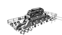
Tracktor robot with place for electrnics by NirDobovizki
...f the parts don't need any infill, print 4 wheels and 1 each of the other stl files (i recommend high infill for the wheels).
thingiverse
free
Fume extractor by NirDobovizki
...ingiverse.com/thing:193647
designed with sketchup, fixed with microsoft 3d builder, sliced with cura and printed on a robo 3d r1+
thingiverse
free

Simple cabinet door handle by NirDobovizki
...ions for the parts above it.
design with onshape, cleaned with microsoft 3d builder, sliced with cura and printed on a robo3d r1+
thingiverse
free

ESP 01 Connector by NirDobovizki
...in your own designs.
designed with sketchup, stl cleaned with microsoft 3d builder, sliced with cura and printed on my robo3d r1+
thingiverse
free

Durable Fully Printable Customizable Spring by NirDobovizki
...akes it work.
i tested it in abs and petg and it worked really well (petg seems to be more durable), didn't try with pla yet.
Supply
3d_export
$5

black supply
...black supply
3dexport
black supply size: 57.9 x 29.2 x 34 sm
3d_export
free

office supplies
...office supplies
3dexport
turbosquid
$75

Supply Helicopter
... available on turbo squid, the world's leading provider of digital 3d models for visualization, films, television, and games.
turbosquid
$65
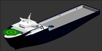
Supply Ship
... available on turbo squid, the world's leading provider of digital 3d models for visualization, films, television, and games.
turbosquid
$19

Power Supply
... available on turbo squid, the world's leading provider of digital 3d models for visualization, films, television, and games.
turbosquid
$5

school supplies
... available on turbo squid, the world's leading provider of digital 3d models for visualization, films, television, and games.
3d_export
$10

Supply air duct
...supply air duct
3dexport
supply air duct with two axial fans and hangers
3d_ocean
$15

Office Supplies Pack
...e dispenser eraser markers office paper pencils pens scissors stapler supplies tape tools work
pack of different office supplies.
3d_export
$18

dance supplies-workshop
...dance supplies-workshop
3dexport
dance supplies-workshop<br>3ds max 2015
3ddd
$1

Art Supplies
...art supplies
3ddd
мольберт , краски
318 793 poly count
Robot
3d_ocean
$20

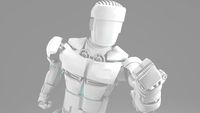
Robot
...robot
3docean
character metal robot robot robotic white
robot model for 3dsmax 2009 and greater
3d_ocean
$45
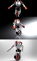
Robot
...robot
3docean
fighing machine robot
a fighting robot from the scrapyard.
3d_ocean
$18
Robot
...robot
3docean
machin robot science fiction
high poly robot.
3d_export
$7
Robot
...robot
3dexport
robot
3d_export
$5
robot
...robot
3dexport
robot
3d_export
free

Robot
...robot
3dexport
robot
turbosquid
$10
Robot/ Alien Robot
...
royalty free 3d model robot/ alien robot for download as max on turbosquid: 3d models for games, architecture, videos. (1442828)
3d_export
$5

robot
...robot
3dexport
robot in blender
3ddd
$1
robot
...robot
3ddd
робот
robot
3ddd
$1

Robot
...robot
3ddd
робот
robot
Power
turbosquid
$100
power
...ower
turbosquid
royalty free 3d model power for download as on turbosquid: 3d models for games, architecture, videos. (1421990)
3d_export
$5

Power
...power
3dexport
3d_export
$5
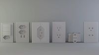
power outlets
...power outlets
3dexport
power outlets
3ddd
$1
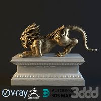
lion power
...lion power
3ddd
лев , статуя
lion power gold sculpture
3ddd
$1
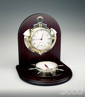
Sea Power
...
компас , море , часы
часы с компасом sea power
3ddd
free
Meridiani / Power
...power
3ddd
meridiani , круглый
стол power производитель meridiani, диаметр 120,высота 67
3d_export
$5

Power Surge
...power surge
3dexport
the power surge is a all mesh carnival ride to lower in game part count and lag
turbosquid
$8
Airport Ground Power Unit (AXA Power )
... available on turbo squid, the world's leading provider of digital 3d models for visualization, films, television, and games.
turbosquid
$50

Power Houser
...rbosquid
royalty free 3d model power houser for download as on turbosquid: 3d models for games, architecture, videos. (1333800)
3d_export
$5

power outlet
...power outlet
3dexport
power outlet<br>format file maya 2018, 3d max 2017, obj, fbx