Thingiverse
Robie Jr Remote with Arduino by Rick100
by Thingiverse
Last crawled date: 4 years, 7 months ago
I bought this Radio Shack Robie Jr on Ebay several months ago. It was listed as a parts only machine and was in pretty bad shape with no remote, missing grippers and the gears on the wheels were stripped. I had another Robie in good shape with a remote so I decided to reproduce it's remote with a 3d printed case and an Arduino controller.
The remote doesn't use RF or IR signals like most of the remotes were familiar with. It uses ultrasonic sound. That means we need an ultrasonic transducer for the Arduino to drive. Fortunately, they're cheap and easy to find now because they're used in the ultrasonic distance measuring modules for hobby robots. I got the one I used from a Banggood HC-SR04 module. I just desoldered the TX transducer from the board and drove it directly from 2 arduino digital pins.
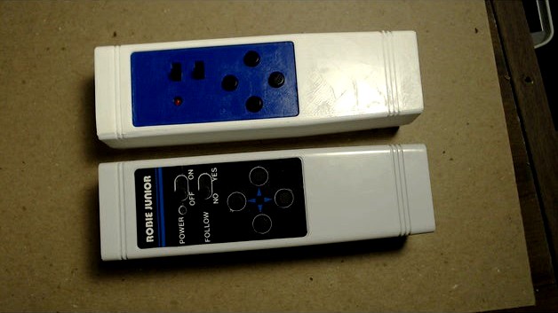
First I needed to examine the signals coming from the working Robie Jr remote I had. To do that, I used one of the cheap Ebay Logic analyzers. I took the remote apart and with a little reverse engineering I found the pin coming from the micrcontroller that drives its transducer. The remote has four direction buttons and a follow switch. When the follow switch is on, the robot heads toward the remote. The robot has an ultrasonic reciever in each of its shoulders so it can determine which direction it needs to steer to. I used the Logic analyzer to record the signals from the remote for each direction button and the follow switch.
The protocol is pretty simple. When the forward button is pressed the remote puts out a constant 41.7 KHz signal. The other direction buttons and the follow switch produce a 1.982 millisecond burst of the 41.7 KHz carrier signal followed by a silent period and then another 1.982 millisecond burst. That is repeated until the button is released. The length of the silent period varies depending on the button pressed.
Here are the values for each direction:
Forward: continuous 41.7KHz carrier
Reverse: 1.982 millisecond bursts of carrier seperated by .143 seconds of silence
Left: 1.982 millisecond bursts of carrier seperated by .133 seconds of silence
Right: 1.982 millisecond bursts of carrier seperated by .123 seconds of silence
Follow: 1.982 millisecond bursts of carrier seperated by .113 seconds of silence
The code was written using version 1.8.5 of the Arduino IDE. Some of the delays were produced using delay loops, so future changes in the IDE or compiler might break the code. I'm sure the code could be done better but it works.
The remote is my 2nd project with Fusion 360 and I'm still learning. The case is made of 5 parts. The top, bottom, front, switch plate, and clamp. The switch plate is the only part that is printed with support. I super glued the switch plate to the top. I printed all the parts on an Ender 2 at .2 layer height.
parts needed:
Arduino pro mini 5V 16M:
battery springs: https://www.banggood.com/10-Pairs-Silver-Tone-Metal-Battery-Spring-Plate-Set-for-AA-AAA-Batteries-p-1046111.html
slide switches: https://www.banggood.com/10Pcs-Black-Mini-Size-SPDT-Slide-Switches-On-Off-100V-2A-DIY-Material-p-1011746.html
tactile switches: https://www.banggood.com/100Pcs-Tactile-Push-Button-Switch-Tact-Switch-6X6X10mm-4-Pin-DIP-p-1000844.html
caps for switches: https://www.banggood.com/20Pcs-6x6x12mm-Momentary-4pin-Push-Button-Micro-Tactile-Tact-Switch-w-Cap-p-1205166.html
ultrasonics: https://www.banggood.com/5Pcs-HC-SR04-Ultrasonic-Ranging-Sensor-Ultrasonic-Module-For-Arduino-p-943142.html
prototype board: https://www.banggood.com/5Pcs-7x9cm-PCB-Prototyping-Printed-Circuit-Board-Prototype-Breadboard-p-944697.html
3MM screws of different lengths. Four of 6MM length for connecting the clamp and switch pcb to switch plate. Four of 10MM for connecting top case to bottom.
A 3mm led for power indicator>
The remote has a build in battery compartment that holds 3 AAAs. The solder tabs on the battery springs are designed to extend through the bottom of a battery case. They have a barb that holds them in place. I designed my battery compartment so the solder tabs are on top. So you have to flatten out the barbs with pliers.
The power and follow switches are held in place by a printed clamp so you have to use switches of the right size.
I used Dupont wires and headers on the Arduino Pro Mini. They use up a lot of room and I had to bend the headers down so they would fit in the case. If I build another one, I would just solder the wires to the board. The Arduino is hot glued in the case. I used a 2 X 6 male header soldered to a piece of prototype board as a power distribution strip for the Dupont connectors.
The range of the one I build is about 5.5 Meters.
The remote doesn't use RF or IR signals like most of the remotes were familiar with. It uses ultrasonic sound. That means we need an ultrasonic transducer for the Arduino to drive. Fortunately, they're cheap and easy to find now because they're used in the ultrasonic distance measuring modules for hobby robots. I got the one I used from a Banggood HC-SR04 module. I just desoldered the TX transducer from the board and drove it directly from 2 arduino digital pins.
First I needed to examine the signals coming from the working Robie Jr remote I had. To do that, I used one of the cheap Ebay Logic analyzers. I took the remote apart and with a little reverse engineering I found the pin coming from the micrcontroller that drives its transducer. The remote has four direction buttons and a follow switch. When the follow switch is on, the robot heads toward the remote. The robot has an ultrasonic reciever in each of its shoulders so it can determine which direction it needs to steer to. I used the Logic analyzer to record the signals from the remote for each direction button and the follow switch.
The protocol is pretty simple. When the forward button is pressed the remote puts out a constant 41.7 KHz signal. The other direction buttons and the follow switch produce a 1.982 millisecond burst of the 41.7 KHz carrier signal followed by a silent period and then another 1.982 millisecond burst. That is repeated until the button is released. The length of the silent period varies depending on the button pressed.
Here are the values for each direction:
Forward: continuous 41.7KHz carrier
Reverse: 1.982 millisecond bursts of carrier seperated by .143 seconds of silence
Left: 1.982 millisecond bursts of carrier seperated by .133 seconds of silence
Right: 1.982 millisecond bursts of carrier seperated by .123 seconds of silence
Follow: 1.982 millisecond bursts of carrier seperated by .113 seconds of silence
The code was written using version 1.8.5 of the Arduino IDE. Some of the delays were produced using delay loops, so future changes in the IDE or compiler might break the code. I'm sure the code could be done better but it works.
The remote is my 2nd project with Fusion 360 and I'm still learning. The case is made of 5 parts. The top, bottom, front, switch plate, and clamp. The switch plate is the only part that is printed with support. I super glued the switch plate to the top. I printed all the parts on an Ender 2 at .2 layer height.
parts needed:
Arduino pro mini 5V 16M:
battery springs: https://www.banggood.com/10-Pairs-Silver-Tone-Metal-Battery-Spring-Plate-Set-for-AA-AAA-Batteries-p-1046111.html
slide switches: https://www.banggood.com/10Pcs-Black-Mini-Size-SPDT-Slide-Switches-On-Off-100V-2A-DIY-Material-p-1011746.html
tactile switches: https://www.banggood.com/100Pcs-Tactile-Push-Button-Switch-Tact-Switch-6X6X10mm-4-Pin-DIP-p-1000844.html
caps for switches: https://www.banggood.com/20Pcs-6x6x12mm-Momentary-4pin-Push-Button-Micro-Tactile-Tact-Switch-w-Cap-p-1205166.html
ultrasonics: https://www.banggood.com/5Pcs-HC-SR04-Ultrasonic-Ranging-Sensor-Ultrasonic-Module-For-Arduino-p-943142.html
prototype board: https://www.banggood.com/5Pcs-7x9cm-PCB-Prototyping-Printed-Circuit-Board-Prototype-Breadboard-p-944697.html
3MM screws of different lengths. Four of 6MM length for connecting the clamp and switch pcb to switch plate. Four of 10MM for connecting top case to bottom.
A 3mm led for power indicator>
The remote has a build in battery compartment that holds 3 AAAs. The solder tabs on the battery springs are designed to extend through the bottom of a battery case. They have a barb that holds them in place. I designed my battery compartment so the solder tabs are on top. So you have to flatten out the barbs with pliers.
The power and follow switches are held in place by a printed clamp so you have to use switches of the right size.
I used Dupont wires and headers on the Arduino Pro Mini. They use up a lot of room and I had to bend the headers down so they would fit in the case. If I build another one, I would just solder the wires to the board. The Arduino is hot glued in the case. I used a 2 X 6 male header soldered to a piece of prototype board as a power distribution strip for the Dupont connectors.
The range of the one I build is about 5.5 Meters.