Thingiverse
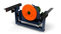
Ribber for CSM: Circular Sock Knitting Machine by MrRoboto19
by Thingiverse
Last crawled date: 3 years, 1 month ago
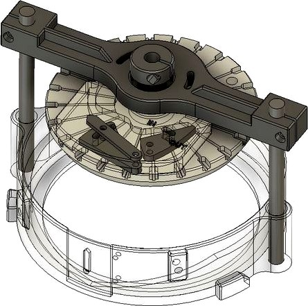
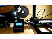
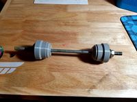
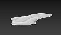
This is an experimental ribber I designed for my CSM circular sock knitting machine (https://www.thingiverse.com/thing:4695746).
DISCLAIMER: I haven't made or tested this. Unfortunately, I am having problems with my 3D printer and it will be a while before I can make it. But, I thought there might be a few adventurous souls out there that are willing to be a guinea p.. err, Official Tester. Be warned that it may not work and you will probably have to remake some parts. My only request is that if you make it, please post comments here when you are done (good or bad).
Version History:
v3: Release 3/7/21
Parts List:
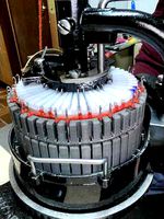
Ribber needles (style #1, 12 ga, for Auto Knitter / Legare, regular size hook): https://angoravalley.com/sockmachines/accessories.html
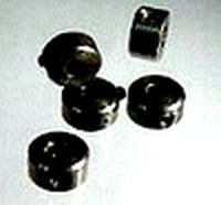
(2X) Skateboard bearings: 8mm ID x 22mm OD x 7mm thick
O1 drill rod (unhardened / tight tolerance): 1/8" and 8mm diameters
Misc. lengths of M3 cap screws, nuts, and washers
30 min epoxy
3D Printing:
PETG or ABS. Not sure how PLA would work (may be too brittle).
0.2mm layer height. 4 layers top / bottom. 4 perimeters. 20% infill.
I tried to design everything without supports, but you may need them on a few parts.
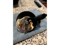
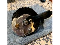
Assembly:
You will need the cams from V2 to work with the new Cam Shell.
Cut 2 pieces of 8mm drill rod to 4-1/8" long. Slightly chamfer ends and push into holes in the Cam Shell until they touch the bottom. Don't glue. This should be a easy fit, but not sloppy.
Cut 1 piece of 8mm drill rod to 2-1/8" long. Slightly chamfer ends. If you will be switching ribber dials often, make sure the rod will slide easily into the bearings. If not, polish entire OD with very fine sandpaper or steel wool.
Sand 3/8" of one end and glue into the Dial Adjuster. It should be flush with the "non flat" side. Wait for glue to set.
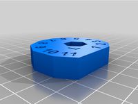
Push Dial onto the 2-1/8" drill rod. It should be able to turn easy, but not be sloppy.
Add screw thru hole on top edge of Dial, thru the slot in the Dial Adjuster, and into the plastic Nut.
Cut 1 piece of 1/8" drill rod to 3/8" long. Slightly chamfer ends. Sand 0.15" of one end (thickness of the cam) and glue into the In Out Cam. It should be flush with the side that has the hex hole for the nut. Push into Tappet plate. Sand sides of Cam as needed so it twists easily. Add screw / washer / nut.
Do the same with the Tension Cam, but cut the drill rod to 1/2". Add pointer to top of Tappet.
Add 2 nuts to under side of Tappet plate. Push a bearing into the Tappet plate and push assembly onto the 2-1/8" drill rod.
Push a bearing into the Arm and push onto 2-1/8" drill rod. Add 2 screws with washers.
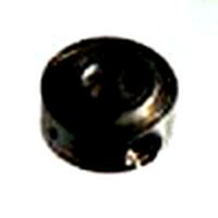
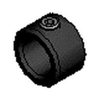
Push Shaft Collar onto 2-1/8" drill rod. The small end should point toward the bearing. Add screw / nut. Make sure all pieces are touching on the 2-1/8" drill rod and tighten Shaft Collar (there should be a small gap between the Dial and Tappet so the Dial can turn freely.
Push assembly onto the (2) 4-1/8" rods in the Cam Shell. Position as needed and tighten with screws / nuts.
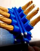
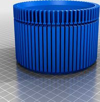
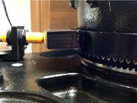
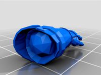
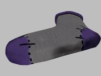
Note how Cylinder Stop sits inside the Cylinder (see picture). Sand both pieces where they will touch and epoxy together. I thought it might be easier than making an entire new cylinder. It can be positioned anywhere in the Cylinder, but I would place it opposite from where you do your heels (so forks won't get in the way).
Say a small prayer to the "Cranky" gods and good luck! I realize the Dial adjuster is unconventional, but hopefully it will work OK.
Have fun! Steve
DISCLAIMER: I haven't made or tested this. Unfortunately, I am having problems with my 3D printer and it will be a while before I can make it. But, I thought there might be a few adventurous souls out there that are willing to be a guinea p.. err, Official Tester. Be warned that it may not work and you will probably have to remake some parts. My only request is that if you make it, please post comments here when you are done (good or bad).
Version History:
v3: Release 3/7/21
Parts List:
Ribber needles (style #1, 12 ga, for Auto Knitter / Legare, regular size hook): https://angoravalley.com/sockmachines/accessories.html
(2X) Skateboard bearings: 8mm ID x 22mm OD x 7mm thick
O1 drill rod (unhardened / tight tolerance): 1/8" and 8mm diameters
Misc. lengths of M3 cap screws, nuts, and washers
30 min epoxy
3D Printing:
PETG or ABS. Not sure how PLA would work (may be too brittle).
0.2mm layer height. 4 layers top / bottom. 4 perimeters. 20% infill.
I tried to design everything without supports, but you may need them on a few parts.
Assembly:
You will need the cams from V2 to work with the new Cam Shell.
Cut 2 pieces of 8mm drill rod to 4-1/8" long. Slightly chamfer ends and push into holes in the Cam Shell until they touch the bottom. Don't glue. This should be a easy fit, but not sloppy.
Cut 1 piece of 8mm drill rod to 2-1/8" long. Slightly chamfer ends. If you will be switching ribber dials often, make sure the rod will slide easily into the bearings. If not, polish entire OD with very fine sandpaper or steel wool.
Sand 3/8" of one end and glue into the Dial Adjuster. It should be flush with the "non flat" side. Wait for glue to set.
Push Dial onto the 2-1/8" drill rod. It should be able to turn easy, but not be sloppy.
Add screw thru hole on top edge of Dial, thru the slot in the Dial Adjuster, and into the plastic Nut.
Cut 1 piece of 1/8" drill rod to 3/8" long. Slightly chamfer ends. Sand 0.15" of one end (thickness of the cam) and glue into the In Out Cam. It should be flush with the side that has the hex hole for the nut. Push into Tappet plate. Sand sides of Cam as needed so it twists easily. Add screw / washer / nut.
Do the same with the Tension Cam, but cut the drill rod to 1/2". Add pointer to top of Tappet.
Add 2 nuts to under side of Tappet plate. Push a bearing into the Tappet plate and push assembly onto the 2-1/8" drill rod.
Push a bearing into the Arm and push onto 2-1/8" drill rod. Add 2 screws with washers.
Push Shaft Collar onto 2-1/8" drill rod. The small end should point toward the bearing. Add screw / nut. Make sure all pieces are touching on the 2-1/8" drill rod and tighten Shaft Collar (there should be a small gap between the Dial and Tappet so the Dial can turn freely.
Push assembly onto the (2) 4-1/8" rods in the Cam Shell. Position as needed and tighten with screws / nuts.
Note how Cylinder Stop sits inside the Cylinder (see picture). Sand both pieces where they will touch and epoxy together. I thought it might be easier than making an entire new cylinder. It can be positioned anywhere in the Cylinder, but I would place it opposite from where you do your heels (so forks won't get in the way).
Say a small prayer to the "Cranky" gods and good luck! I realize the Dial adjuster is unconventional, but hopefully it will work OK.
Have fun! Steve
Similar models
thingiverse
free
8mm threaded rod "nuts" by celebrity208
...gned and printed these hand wheels/thumb screws to thread onto an 8mm rod with an interference fit so they don't spin freely.
thingiverse
free
Mirror/Glass cutting jig
...ss type glass cutter (amazon)
https://smile.amazon.com/gp/product/b01ka5ql6g/ref=ppx_yo_dt_b_asin_title_o04_s00?ie=utf8&psc=1
thingiverse
free
Spool holder by armenio
...rs are needed to avoid the spool to "walk out" of the rod, for this purpose both rod stoppers should be tight together.
thingiverse
free
CR-10 Spool Holder by Flynny
...hter and pushed into creality nut screw.
either use creality spool holder nuts for creality screw, or nut and screw i provided.
thingiverse
free
Gearhart Sock knitting machine Cylinder and Ribber Modified (ribber dia. 109) by Kknits
... change it in program without some weird stuff happening!
i was able to have a working ribber printed for me with these changes.
thingiverse
free
Gearhart Sock knitting Machine Cylinder and Ribber Modified 60 slot (109 dia. ribber) by Kknits
... change it in program without some weird stuff happening!
i was able to have a working ribber printed for me with these changes.
thingiverse
free
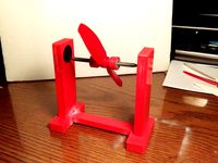
Prop Balancer by Bsand1215
... lot of friction.
all the parts to the stand are interlocking to mount to the other parts requiring a small amount of super glue.
thingiverse
free
1 1/8" and or 1 1/5" headset press
...l fit both 1 1/8" and 1 1/5" bearing cups. i used a 3/8ths" threaded rod with nuts and thick washers on each end.
thingiverse
free
Autoknitter Cylinder and Ribber Dial (48, 60, 64, 72, 80, 96 needles) by yasmin_k
...rk for you - or not.
i won't add the .f3d since it's a mess by now.
if you need different needle counts just let me know.
thingiverse
free
Underberg V8 by jaasball
...6 bolt for crank handle
a handfull of 8mm washers
you need to print:
8 pcs sylinder
2 pcs ende
1 piece sveiv
4 pcs kam.
good luck
Mrroboto19
thingiverse
free
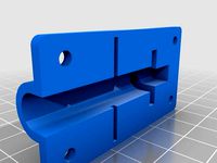
Conveyor Roller Height Cam by MrRoboto19
...ed for rollers on industrial conveyors.
couldn't find a replacement to purchase, so i made several for work.
have fun! steve
thingiverse
free
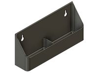
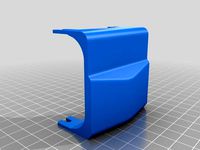
Sink Tip Out Tray by MrRoboto19
...t the sink. it includes a divider and rounded insides. i also included the fusion 360 model so you can modify.
have fun! steve
thingiverse
free

CSM: Circular Sock Knitting Machine by MrRoboto19 by K1nk0
...ng needles for brother knitting machine kh820 kh830 kh860 kh881 kh868 kh940 kh970"
you will need to cut and file each needle
Ribber
thingiverse
free
Gearhart Sock knitting machine Cylinder and Ribber Modified (ribber dia. 109) by Kknits
... change it in program without some weird stuff happening!
i was able to have a working ribber printed for me with these changes.
thingiverse
free
Gearhart Sock knitting Machine Cylinder and Ribber Modified 60 slot (109 dia. ribber) by Kknits
... change it in program without some weird stuff happening!
i was able to have a working ribber printed for me with these changes.
thingiverse
free
Autoknitter Cylinder and Ribber Dial (48, 60, 64, 72, 80, 96 needles) by yasmin_k
...rk for you - or not.
i won't add the .f3d since it's a mess by now.
if you need different needle counts just let me know.
thingiverse
free
Knitting Machine - Singer - Ribber 321 plastic pieces left and right by SuziePerth
... carriage
thanks to my 14 year old son for designing the replacement parts on inventor in order for us to print replacement parts
thingiverse
free
NZAK Simplex 72 Stitch Cylinder and 72 Stitch Ribber by oberholj
...fering an edit to her file for the bigger slots. thank you wbtextile for all your hard work so that i could make my own cylinder.
thingiverse
free
SR155 Racking Gear Cover by eldorin
...plate. fortunately i have a sk155 with the sr155 ribber so i was able to remove and reproduce the...
thingiverse
free
Row counter for sock knitting machine by huelster
...counter available on amazon. mounts off a nzak spare ribber parking...
thingiverse
free
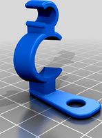
Autoknitter CSM Driving Pin Clip by yasmin_k
...autoknitter driving pin so it can't mess up the ribber timing any...
thingiverse
free

Sock knitting Machine Zylinder for KR850 needles by ScruffyOrc
...zylinder for kr850 needles by scruffyorc thingiverse the kr850 ribber needles are too thin for the original cylinder, resized...
Csm
humster3d
$75
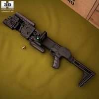
3D model of CornerShot CSM with Glock 21
...3d model of cornershot csm with glock 21 in various file formats. all our 3d models were created maximally close to the original.
3dfindit
free
CSM-11 to CSM-18
...csm-11 to csm-18
3dfind.it
catalog: wmberg
3dfindit
free
CSM-1 to CSM-10
...csm-1 to csm-10
3dfind.it
catalog: wmberg
3dfindit
free
CSM-19 to CSM-28
...csm-19 to csm-28
3dfind.it
catalog: wmberg
thingiverse
free
CSM by gondorp
...csm by gondorp
thingiverse
designed for csm
thingiverse
free
noise marine body - csm - tm
...noise marine body - csm - tm
thingiverse
noise marine body - csm - tm
thingiverse
free
modular csm - parts exploded - 40k by jimjimjimmyjim
...modular csm - parts exploded - 40k by jimjimjimmyjim
thingiverse
modular csm - parts exploded - 40k
thingiverse
free
chaos lord - nurgle csm
...chaos lord - nurgle csm
thingiverse
its time for another reaping
thingiverse
free
CSM Crest
...erse
camborne school of mines 3d crest.
you can change filament half way through to get a two-colour crest.
laboris gloria ludi!
thingiverse
free
CSM connection project by lucan0202
...tradition of central saint martin ma industrial design
course.in this project, we have to build a machine with input and output .
Sock
turbosquid
$7
sock
...ck
turbosquid
royalty free 3d model sock for download as obj on turbosquid: 3d models for games, architecture, videos. (1440718)
3d_export
$25
folded socks calcetines doblados socks display rack calcetin doblado sock socks calcetin calcetin
...rt sock feet wear dirty used realistic cloth socks unisex short fashion clothes foot fur knitted woven plaited character clothing
3ddd
$1
Socks
...socks
3ddd
носок , одежда
носки
turbosquid
$10

Sock
... available on turbo squid, the world's leading provider of digital 3d models for visualization, films, television, and games.
archive3d
free
Sock 3D Model
...l
archive3d
sock toe foot clothing
sock - 3d model (*.gsm+*.3ds) for interior 3d visualization.
turbosquid
$7
sock 2
...
turbosquid
royalty free 3d model sock 2 for download as obj on turbosquid: 3d models for games, architecture, videos. (1440720)
3d_export
$5
Smelly sock 3D Model
...smelly sock 3d model
3dexport
sock smelly sock clothing foot
smelly sock 3d model vizzi 37073 3dexport
turbosquid
$40

Christmas Sock
...e 3d model christmas sock for download as blend, fbx, and obj on turbosquid: 3d models for games, architecture, videos. (1662637)
turbosquid
$7

Christmas Sock
...el christmas sock for download as 3ds, obj, fbx, dae, and stl on turbosquid: 3d models for games, architecture, videos. (1482119)
turbosquid
$5
christmas socks
... available on turbo squid, the world's leading provider of digital 3d models for visualization, films, television, and games.
Knitting
3ddd
$1
knitted map
...knitted map
3ddd
knitted blanket texture
3ddd
$1
knitted carpet
...knitted carpet
3ddd
ковер
this is a knitted carpet with dimansion:
h-310
w-210
design_connected
$18

Knitting Armchair
...knitting armchair
designconnected
menu knitting armchair computer generated 3d model. designed by kofod-larsen, lb.
turbosquid
$2
Knitting Basket
...id
royalty free 3d model knitting basket for download as max on turbosquid: 3d models for games, architecture, videos. (1217866)
3ddd
$1

knitted circular carpet
...knitted circular carpet
3ddd
ковер , круглый
knitted circular carpet
size:d-180sm
3d_ocean
$17

Wave knitted lounge
...ccurate wire. made with v-ray and corona render. low and high-poly model. dimensions: 164 (l) x 62 (w) x 66 (h) cm polygons: 2...
turbosquid
$29

knitted horse
... available on turbo squid, the world's leading provider of digital 3d models for visualization, films, television, and games.
3d_ocean
$4

Knitted wool texture
...clothing color cotton fabric fashion fiber homemade knit knitted knitting mesh natural organic part pattern row surface sweater textile...
design_connected
$16

Knit Dining Armchair
...knit dining armchair
designconnected
ethimo knit dining armchair computer generated 3d model. designed by norguet, patrick.
3d_ocean
$5
Seamless Knitted Texture
...g and animation. created from a high quality scan. displacement, normal, occlusion and specular jpg maps are all included in t...
Circular
3ddd
$1

Circular Library
...circular library
3ddd
библиотека , стеллаж
circular library
3d_export
$5
Horizontal circular saw
...horizontal circular saw
3dexport
horizontal circular saw
turbosquid
$10
Circular sword
...osquid
royalty free 3d model circular sword for download as on turbosquid: 3d models for games, architecture, videos. (1402076)
3ddd
$1
Noguchi circular table
...noguchi circular table
3ddd
круглый
noguchi circular table
turbosquid
$10
Circular Shelf
...alty free 3d model circular shelf for download as max and obj on turbosquid: 3d models for games, architecture, videos. (1315073)
turbosquid
$5
Circular Ottoman
...ty free 3d model circular ottoman for download as obj and fbx on turbosquid: 3d models for games, architecture, videos. (1414413)
3d_export
$10
Circular machine
...circular machine
3dexport
turbosquid
$6
Circular Bed
... free 3d model circular bed for download as max, fbx, and prj on turbosquid: 3d models for games, architecture, videos. (1466410)
3ddd
$1
Circular Seating
...дульный
circular seating in 3dsmax 2010 & 2012 vray scene with maps & materials carefully unwrapped, obj format included.
3ddd
$1
knitted circular carpet
...knitted circular carpet
3ddd
ковер , круглый
knitted circular carpet
size:d-180sm
Machine
archibase_planet
free

Machine
...machine
archibase planet
sewing-machine sewing machine equipment
singer machine- 3d model for interior 3d visualization.
archibase_planet
free

Machine
...hine
archibase planet
percolator equipment coffee-machine
machine n230708 - 3d model (*.gsm+*.3ds) for interior 3d visualization.
archibase_planet
free
Machine
...chibase planet
percolator coffee-machine kitchen equipment
coffee machine - 3d model (*.gsm+*.3ds) for interior 3d visualization.
archibase_planet
free

Slot machine
...ase planet
slot machine slot-machine playing machine
slot machine n260311 - 3d model (*.gsm+*.3ds) for interior 3d visualization.
turbosquid
$7

Machine
...ne
turbosquid
royalty free 3d model machine for download as on turbosquid: 3d models for games, architecture, videos. (1391792)
3d_ocean
$10
War machine
...war machine
3docean
camuflage machine robot war war machine
war machine created in 3dmax 2009 15.497-poly count
turbosquid
$7
machine
...turbosquid
royalty free 3d model machine for download as obj on turbosquid: 3d models for games, architecture, videos. (1452674)
3d_ocean
$12
Weighing-machine
...weighing-machine
3docean
market shop weighing-machine
3d model weighing-machine
archibase_planet
free

Sewing machine
...ine
archibase planet
sewing machine sewing-machine
sewing machine n080311 - 3d model (*.gsm+*.3ds) for interior 3d visualization.
archibase_planet
free
Coffee machine
...se planet
coffee machine percolator coffee-machine
coffee machine n010715 - 3d model (*.gsm+*.3ds) for interior 3d visualization.