Thingiverse
RFID Filament Weighing Scales by cirion76
by Thingiverse
Last crawled date: 3 years, 1 month ago
License for all provided files: CC-BY-NC-SA 4.0 (https://creativecommons.org/licenses/by-nc-sa/4.0/legalcode)
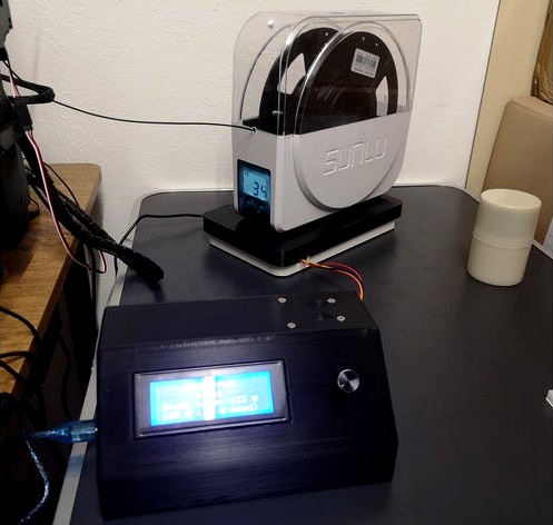
RFID Filament Scales
If you got addicted to 3D printing like me, keeping track of what remains on dozens of filament spools gets more and more tedious. My solution: Affordable weighing scales that can scan an RFID tag sticker on every spool to keep track of the spools' (tare) weights.
Current features/limitations:
Supports cheap 13.56 MHz RFID tags (MIFARE Classic).
Stores up to 510 tare weights (including name and color strings, up to 20 characters each).
Tare weight can be entered by known spool weight or known filament weight.
Calibration by either 100 g, 200 g, 500 g or 1 kg weights.
Free browsing through all entries without the need to re-scan the corresponding tag.
Firmware is easily portable to other languages (limited by the LCD's capabilities, of course).
Minimal soldering required (if at all, you only have to solder a few pin headers).
Basic consumption tracking.
Overall accuracy is about ±2 g (but also depends on your load cell, the HX711 module and your environment). However, due to varying filament tension you'll see much larger (or even huge) fluctuations when used during printing. If you want to smooth this out, you'll have to edit config.h in the HX711_ADC library's directory and set SAMPLES to a higher value (must be a power of two, max. 128). This will increase settling time, though (from 1.8 s default to 13 s for 128 samples).
You should currently consider this project (including this documentation) a very early draft. Don't hold me responsible for any mistakes that might harm you or destroy your hardware - only build this if you know what you're doing! This should probably not be your first project involving a µC.
If you want to speed up development and/or documentation, you might consider a donation ;-)
Printing
Material doesn't really matter, but I recommend TPU (or even softer materials if you can print them) for the encoder knob (just for haptic reasons) and any reasonably stiff material (e. g. PLA) for the weighing unit. Everything should print fine with 0.2 mm layers, but for perfect accuracy you'll need 0.1 mm layers or less at least for the controller unit.
Both top parts and - if needed - the encoder knob should be printed upside down. The controller top needs supports for the LCD window (unless your printer can easily bridge 100 mm) and maybe the encoder hole, all the rest prints without supports.
Bill of Materials
1x Arduino Mega or clone (actually an Uno would suffice for the current version, but wouldn't leave much room for future improvements, and besides, I already had the Mega ;-))
1x 20x4 LCD module (HD44870/SC2004) with I²C interface (https://www.amazon.de/gp/product/B007XRHBKA)
1x KY-040 rotary encoder module (https://www.amazon.de/gp/product/B07CMSHWV6)
1x MFRC522 RFID reader module (https://www.amazon.de/gp/product/B08G15MRLV)
1x AT24C256 EEPROM module (https://www.amazon.de/gp/product/B07XTBXGXW)
1x 5 kg load cell (standard chinesium 80x12.7x12.7 mm model) with HX711 module (I used this set https://www.amazon.de/gp/product/B07GRGT3C3)
1x mini breadboard for power and I²C bus distribution (https://www.amazon.de/gp/product/B07GKVTM88, if you assemble your own wiring you can drop this)
1x active-low beeper module (https://www.amazon.de/gp/product/B07D3NYCDV, optional, can be directly plugged into the mini breadboard)
lots of 20 cm jumper wires (Dupont), male-to-male and male-to-female (or, of course, any other suitable means of wiring you can assemble yourself)
2x M2.6x6 self-tapping screws (for KY-040 module)
10x M3x6 self-tapping screws (for Arduino, Display and HX711 module, be careful not to damage the SMD parts on the HX711 module - if in doubt only use one screw)
4x M3x8 (or longer) countersunk screws (for RC522 module)
4x M4x6 (or longer) countersunk screws (for the controller enclosure)
2x M4x20 (or slightly longer) countersunk screws (for the load cell unit top)
2x M5x20 (or slightly longer) countersunk screws (for the load cell unit bottom)
4x M3 nuts (for RC522 module, again be careful not to damage the SMD parts)
8x anti-slip pads (optional)
13.56 MHz RFID tags for your spools (e. g. https://www.amazon.de/gp/product/B01HEU96C6)
a 100 g, 200 g, 500 g or 1000 g calibration weight
Firmware Dependencies:
You'll need the following libraries for the provided Arduino IDE .ino source:
HX711_ADC (https://github.com/olkal/HX711_ADC, can be installed from within Arduino IDE)
MFRC522 (https://github.com/miguelbalboa/rfid, can be installed from within Arduino IDE)
New-LiquidCrystal (https://github.com/fmalpartida/New-LiquidCrystal)
RotaryEncoder (https://github.com/mathertel/RotaryEncoder, can be installed from within Arduino IDE)
extEEPROM (https://github.com/JChristensen/extEEPROM, can be installed from within Arduino IDE)
Wiring:
EEPROM & Display: VCC to Arduino 5V, GND to Arduino GND, SDA to Arduino SDA (communication pin 20), SCL to Arduino SCL (communication pin 21)
KY-040: VCC/+ to Arduino 5V, GND to Arduino GND, CLK/A to Arduino communication pin 18, DT/B to Arduino communication pin 19, SW to Arduino digital/PWM pin 2
RC522: 3.3V to Arduino 3V3 (IMPORTANT! 5V will probably destroy the module!), GND to Arduino GND, RST to Arduino digital/PWM pin 6, SDA to Arduino digital/PWM pin 7, SCK to Arduino SCK (digital pin 52), MOSI to Arduino MOSI (digital pin 51), MISO to Arduino MISO (digital pin 50)
HX711: VCC to Arduino 5V, GND to Arduino GND, CLK to Arduino digital/PWM pin 4, DAT/DT to Arduino digital/PWM pin 5
Beeper: VCC to Arduino 5V, GND to Arduino GND, I/O to Arduino digital pin 22
For now I hope you can figure out assembly and power/signal distribution via the breadboard yourself ;-)
A few notes:
If you haven't flashed the firmware yet, the beeper will beep continuously (unless you have replaced it with an active-high one and changed the source code accordingly). This is annoying, but normal. So flash first.
If you have trouble putting the EEPROM module in its place, heat up the small clips a little and bend them back after you inserted the module.
The arrow on the load cell needs to point downward.
Keep the wires between HX711 and load cell twisted.
I do know that you should use a level shifter between MFRC522 and Arduino - however, it works reliably without one as long as you don't power the module with 5V. Besides, most easily available level shifter modules are either too slow for SPI or they (e. g. the TXS0108E) need more driving current than the MFRC522 can provide. An affordable alternative would be much appreciated.
A proper connection between controller and weighing unit (via an ordinary ethernet cable) will be added some time in the future. All further development depends on your input and support ;-)
If you don't print the encoder knob with a flexible material you'll probably need to scale it up a little.
Similar models
grabcad
free

Load Cell 5kg HX711
...module and microcontroller.
https://www.amazon.de/-/en/gp/product/b07l81bqb6/ref=ppx_yo_dt_b_search_asin_title?ie=utf8&psc=1
3dwarehouse
free

MFRC522 RFID Reader
...mfrc522 rfid reader
3dwarehouse
rfid reader module for arduino
thingiverse
free

Load cell frame by indrekluuk
... frame by indrekluuk
thingiverse
load cell frame for a 20kg four-wire load cell. can be used with an arduino and an hx711 module
3dwarehouse
free

Funduino RFID-RC522
...funduino rfid-rc522
3dwarehouse
rfid reader module for arduino
thingiverse
free

Desktop RFID reader 13,56MHz + arduino nano by dgoma
...tware is not ready. i'm writting arduino with the library https://github.com/miguelbalboa/rfid and on my mac with processing
thingiverse
free

Filament Weight measure using HX711 Load Cell with Spool holder by ADMC
...ink to load cell weight sensor hx711 module:https://www.aliexpress.com/item/32949395083.html?spm=a2g0s.9042311.0.0.27424c4d4utje7
thingiverse
free

rfid box for rc522 and arduino nano by Ifrit70
...of the box or the rc522 depending of your module (chineese pcb aren't perfectly identical), or your 3d printers calibrations.
thingiverse
free

3D Filament Spool Scale / Meter Indicator by smokinpuppy
... (ar)
button:
vcc -> 5v (ar)
sin -> d7 (ar)
gnd -> gnd (ar)
knob:
vcc -> 5v (ar)
sin -> lcd(v0)
gnd -> gnd (ar)
thingiverse
free

Handbrake Load Cell by Javi91ac
...51 loadcell 200kg.
i use arduino micro and hx711.
arduino code in: https://github.com/javi91ac/handbrakeloadcell
work in progress
thingiverse
free

RFID RC522 for arduino mega R3 with lcd display by jimbo_akimbo
...bo
thingiverse
i created this for a little project , its designed for an arduino mega r3 , a rfid rc522 module and a lcd screen.
Cirion76
thingiverse
free

Yin Yang Coaster by cirion76
...or hot beverages. then obviously don't use pla.
if you want the bicolor design, change filament after 1 mm (half the height).
thingiverse
free

Anycubic Mega X Bed Cooler by cirion76
... and bottom beams)
to add:
2x 80mm fan (plus wiring)
8x m4x40 screws
8x m4 nuts
8x m4 washers (optional)
2x fan grille (optional)
Rfid
turbosquid
$20

RFID Reader
...royalty free 3d model rfid reader for download as obj and 3dm on turbosquid: 3d models for games, architecture, videos. (1450180)
3d_export
$24

Rfid gate 3D Model
... frequency identification gate gates transport logistic tag shipping depot rfdi security
rfid gate 3d model tartino 3854 3dexport
3d_export
$5

rfid door intercom with cam
...ecular<br>**1 material **<br>remember visit my profile for more 3d models and textures<br>thanks for watching!!
thingiverse
free

RFID by MeliMaker3d
...rfid by melimaker3d
thingiverse
diseño del simbolo rfid
thingiverse
free

rfid box by sanyok661
...rfid box by sanyok661
thingiverse
rfid box
thingiverse
free

TAG RFID by lusho01
...tag rfid by lusho01
thingiverse
tag rfid nfc
thingiverse
free

RFID Fob by Schmity47
...verse
this is a rfid keyfob for a .91 inch by .04 inch round rfid chip. not sure if fitment will be perfect, but lmk if its not.
thingiverse
free

RFID-RC522 case
...rfid-rc522 case
thingiverse
two part case or cover for a rfid reader module.
thingiverse
free

RFID Hook by WickertD
...rfid hook by wickertd
thingiverse
hook mounted to a servo motor to pick up the rfid
thingiverse
free

rfid enclosure
...rfid enclosure
thingiverse
really simple project for most
Weighing
3d_ocean
$12
Weighing-machine
...weighing-machine
3docean
market shop weighing-machine
3d model weighing-machine
3d_ocean
$7

Weighing Machine
...ighing machine
3docean
3d model design indoor metal vray weigher weighing wachine
old weighing machine 3d model. v-ray materials.
turbosquid
$10

weighing scale
...d model weighing scale for download as max, max, fbx, and obj on turbosquid: 3d models for games, architecture, videos. (1587984)
turbosquid
$10

weighing(1)
... available on turbo squid, the world's leading provider of digital 3d models for visualization, films, television, and games.
turbosquid
$10

Weighing Machine
... available on turbo squid, the world's leading provider of digital 3d models for visualization, films, television, and games.
turbosquid
$5

Weigh Station
... available on turbo squid, the world's leading provider of digital 3d models for visualization, films, television, and games.
turbosquid
$5

Weighing machine
... available on turbo squid, the world's leading provider of digital 3d models for visualization, films, television, and games.
turbosquid
$3

Weighing-machine
... weighing-machine for download as c4d, 3ds, dae, fbx, and obj on turbosquid: 3d models for games, architecture, videos. (1606245)
turbosquid
$450

Weighing machine
...achine for download as max, sldas, sldas, fbx, ige, and sldas on turbosquid: 3d models for games, architecture, videos. (1534102)
turbosquid
$39

Portable Weighing Scale
...l portable weighing scale for download as blend, fbx, and obj on turbosquid: 3d models for games, architecture, videos. (1469387)
Filament
3ddd
$1
Filament Cage
...filament cage
3ddd
лофт , filament cage
модель бра, делалась по фото!
turbosquid
$3
FILAMENT COUNTER
...d
royalty free 3d model filament counter for download as stl on turbosquid: 3d models for games, architecture, videos. (1563049)
3d_export
$5

Filament lamp 3D Model
...filament lamp 3d model
3dexport
filament lamp 3d model kevin 54161 3dexport
3d_export
$5

Filament bulb candle 3D Model
...filament bulb candle 3d model
3dexport
filament bulb-candle
filament bulb candle 3d model kevin 54163 3dexport
3d_export
$5

Filament led light bulb
...filament led light bulb
3dexport
realistic 3d model of filament light bulb with v-ray materials.
3d_export
$5

Filament led light bulb
...filament led light bulb
3dexport
realistic 3d model of filament light bulb with v-ray materials.
3d_export
$5

Filament led light bulb
...filament led light bulb
3dexport
realistic 3d model of filament light bulb with v-ray materials.
3d_export
$5
Filament led light bulb
...filament led light bulb
3dexport
realistic 3d model of filament light bulb with v-ray materials.
3d_export
$5

Filament led light bulb
...filament led light bulb
3dexport
realistic 3d model of filament light bulb with v-ray materials.
3ddd
$1
Factory filament metal shade
...factory filament metal shade
3ddd
restoration hardware
restoration hardware. 20th c. factory filament metal shade.
Scales
turbosquid
$20
Weight scale or Bathroom Scale
...ght scale or bathroom scale for download as max, fbx, and obj on turbosquid: 3d models for games, architecture, videos. (1664576)
turbosquid
$19

Scale
...e
turbosquid
royalty free 3d model scale for download as fbx on turbosquid: 3d models for games, architecture, videos. (1411722)
turbosquid
$5
Scales
...s
turbosquid
royalty free 3d model scales for download as ma on turbosquid: 3d models for games, architecture, videos. (1393439)
turbosquid
$40

Scale
... available on turbo squid, the world's leading provider of digital 3d models for visualization, films, television, and games.
turbosquid
$17
Scales
... available on turbo squid, the world's leading provider of digital 3d models for visualization, films, television, and games.
turbosquid
$12

Scale
... available on turbo squid, the world's leading provider of digital 3d models for visualization, films, television, and games.
turbosquid
free

Scale
... available on turbo squid, the world's leading provider of digital 3d models for visualization, films, television, and games.
3d_export
$7

of scales
...s have a flat point of support. the samples are rendered in the standard cinema 4d renderer. enjoy your use and creative success.
3d_export
$5
scale knob
...scale knob
3dexport
scale knob
3d_export
$20
cartoon weight scale or bathroom scale
...cartoon weight scale or bathroom scale
3dexport
texture size:512px number of texture:1 texture format: png