Thingiverse
Replicator 1/CTC/Flash Forge - Mightyboard to RAMPs 1.4 Conversion (Comprehensive Conversion!) by JMcAz7
by Thingiverse
Last crawled date: 3 years ago
UPDATE (11/17/2017): Well, it's been a while since I updated thanks to life in general. I've switched to a Duet controller after my 1st and 2nd RAMPs boards died since I had one of those laying around (from ANOTHER project I never got started on), and I needed a printer ASAP for a work project. I'm WAY happier with that than I ever was with a Mightboard or RAMPs, and between hooking it up and printing out a test print I spent MAYBE an hour or so (that included firmware configuration). I'll be writing up that conversion in the future, but if this project is any indication it may be a while. :-)
Sorry if I let anybody down. I'm still happy to answer any questions I can for anyone who is going to try and convert to RAMPs. My setup was working just fine for a while, so I'm going to add what I can to this project from my notes and my horrible memory.
Thanks for the support, all.
THIS IS A WORK IN PROGRESS, AND I AM NO EXPERT. Sometimes I get lucky and/or break stuff in useful/educational ways. May as well benefit the community. But, if you destroy your own printer or set your house on fire or something by following my instructions, I am not responsible for it. The liability is on you. I am trying to put forth the best, clearest tutorial possible, but I am still just some guy on the internet. :-)
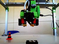
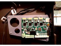
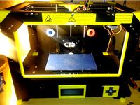
The Mightyboard in my Monoprice Replicator 1 clone died, and instead of dropping the $$$ for a replacement I decided to convert it to run on RAMPS 1.4 instead.
After a lot of Googling, it seems that there wasn't a complete walk-through or tutorial to accomplish this conversion anywhere. I found a lot of bits and pieces scattered across the internet, including quite a bit of conflicting information, so I wanted to put together a comprehensive conversion guide so that you can avoid the litany of headaches I encountered. That includes wiring, firmware installation and configuration, slicer settings, etc. The end goal is simple: Convert a Replicator 1 or similar clone to RAMPS while still performing to the same level of precision or better as the original configuration.
This is an ongoing project on my end, and I'll update this as I progress. I've got my personal printer tuned it, except for a few bugs that I'm trying to sort out now.
I can't guarantee you that I will be able to help answer all your questions real-time, but I'll try to help where I can. I've got 4 kids, a full time job, and I'm carrying a full credit load at Arizona State, so this is a project that may need to get put on the back burner from time to time. If I don't respond to a question in a reasonable amount of time, please don't take it personally.
Current Printer Configuration:
My printer is not 100% stock; I've upgraded/modified a couple of parts over the past 2 years or so. Most of the changes I've already made will not alter the process of converting your printer over to run RAMPS, but when we get to the calibration and tuning part it may be slightly different. Here's the modifications I've made to my printer:
E3D-v6 Hotend with Volcano upgrade
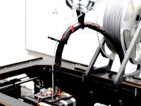
Bowden extruder
Heated build plate (mine did not originally come equipped with one).
Steps (ideally):
1.) Wiring/RAMPS installation
Power supply changes
Thermocouple/thermistor changes.
Stepper/limit switch wiring
2.) Firmware Installation
3.) Firmware Configuration (Marlin)
4.) Slicer Configuration
Simplify 3D
Cura
5.) Maybe - Upgrades (very much a maybe)
Multi-extruder or dual-headed extruder (Cyclops/Chimera)
Auto leveling
Servo vs. Stepper upgrade
Marlin-Controlled Case Fan.
Files Attached
1.) Firmware: Marlin-1.8.1.zip
This is the current build and configuration I'm using.
The z-axis homing issue has been resolved.
Runaway temp settings had to be opened up to prevent false positives. It's still enabled (safety first :-).
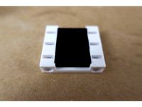
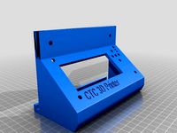
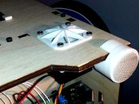
2.) Smart LCD Display Housing
File: LCD_Display_Mount.stl
This LCD display holder was exactly what I was looking to build, but someone beat me to it.
Take a look at the original thing and send a "like" to the creator (xxricsxx) here: http://www.thingiverse.com/thing:1645651
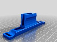
3.) E3D-V6 Dual Hotend Mount
File 1: Hotend_Mount-V006_Dual_Extruder_Bridge_Adjustable.STL
File 2: Hotend_Mount-V006_Dual_Extruder_Cooler_Adjustable.STL
I'm currently using this mount with a single hotend on the right side (minimized the amount of configuration changes when I swapped out the original extruder).
It's a derivative of a mount created by MacNite,. I modified it so that I could run fans that were 40x40x20mm instead of 40x40x10mm since there's a much better selection of thicker fans.
You can view the original and send a like to the original creator here: http://www.thingiverse.com/thing:1446512
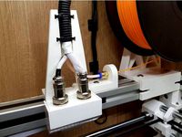
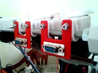
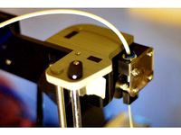
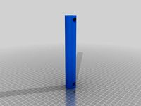
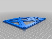
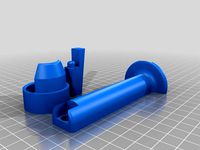
4.) Bowden Extruder with Mount
File 1: Bowden - Monoprice_-_Dual_Extruder_Mount.STL
File 2: Bowden - Monoprice_-_Dual_ExtruderMount-_Retainer.STL
File 3: Bowden - hook.stl
File 4: Bowden - level.stl
File 5: Bowden - tightener.stl
File 6: Bowden - axle.stl
File 7: Bowden - extruder_base_v3.stl
File 8: Bowden - adapter_v2.stl
Designed to fit the Replicator 1 design without drilling additional holes.
Fits 2 steppers for dual extruders.
Derivative of the 3Dator Bowden Extruder created by 3Dator (which can be found here: http://www.thingiverse.com/thing:1318849)
Known Issues - Firmware
Open
Printer is not waiting for the extruder and bed to preheat prior to starting the print. Currently preheating the printer manually before starting the print job. That should be an easy fix, but it's fighting me for some reason...
After homing prior to printing, the z-axis is lowing ~18mm below where it should and it is trying to print in mid-air. I'm currently getting around this by setting my z-axis offset to -18mm in my slicer, but this is a pretty lazy fix and I'm trying to sort out what in the firmware is causing the problem.
Closed
Let's not get too excited. I just started updating this...
Tutorials
1.) Wiring/RAMPS Installation
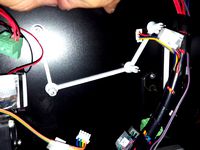
Protip: When removing the harnesses from the printer for this step, label which one came from what axis or extruder.
Since my Mightyboard was dead and I never planned on replacing it with another Mightyboard, I didn't really care to preserve any of the factory connectors on any of the harnesses. My printer came with the Mightyboard Rev. D which mostly used the Molex KK-style connectors while the RAMPS shield uses Dupont-Style connectors. So, I cut off the connector on the board-side of the harness.
You can purchase kits and crimpers for the Dupont connectors on Amazon or Ebay, but I've had issues with these in the past (probably operator error) so I just purchased jumpers with the connectors I needed on them from Ebay and used them as pigtails.
We need to re-terminate the following harnesses on the board side:
X/Y/Z-axis steppers
Extruder(s)
Endstops
Heated build plate
Extruder & mainboard fan
You can remove the following components. We won't be using them any more.
Original LCD
Keypad/SD card slot
Mightyboard
Ribbon cables between LCD/Keypad/Mightyboard
24VDC power supply
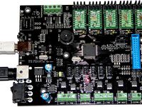
1. X/Y/Z-axis steppers
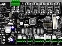
Both the Mightboard and RAMPS use 4 pin connectors for the steppers. It is important that you realize that the pinout on the RAMPS board is different than the Mightboard, so if you connected the steps to RAMPS and leave the connections the same pin-to-pin (e.g stepper pin 1 to RAMPS pin 1, stepper pin 2 to RAMPS pin 2, etc) you may burn up a stepper or possibly just make an annoying noise. Either way, not good.
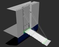
The image below shows the stepper connections on both the Mightyboard and the RAMPS board. You can see that they are different.
If you are looking at the Mightyboard such that the ribbon cable connector is on the right side, then the pinout for the stepper motors will be (from left to right):
Pin 1 = 1A (yellow)
Pin 2 = 1B (red)
Pin 3 = 2A (black)
Pin 4 = 2B (orange)
However, if you look at the RAMPS shield such that the power connectors are on the left (the ones with the screw terminals), the pinout for the steppers is as follows:
Pin 1 = 2B
Pin 2 = 2A
Pin 3 = 1A
Pin 4 = 1B
To maintain the same ordering, connect the new connector so that the following pins connect:
MB - to - RAMPS
Pin 1 - to - Pin 3
Pin 2 - to - Pin 4
Pin 3 - to - Pin 2
Pin 4 - to - Pin 1
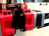
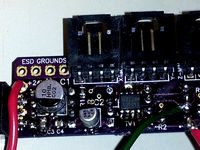
It should look like this when you're done wiring. You need to do this for all stepper motor harnesses and extruder harnesses.
Endstop, heater, and thermistor wiring will be added soon!
Updates/Change log
3/9/17 - Project start.
3/10/17 - Change log added; Baseline printer configuration added; Uploaded and renamed stl files for LCD housing, bowden extruders, and E3D-v6 hotend.
3/11/17 - Added stepper wiring diagram.
6/10/17 - Current firmware added (Marlin 1.8.1).
Sorry if I let anybody down. I'm still happy to answer any questions I can for anyone who is going to try and convert to RAMPs. My setup was working just fine for a while, so I'm going to add what I can to this project from my notes and my horrible memory.
Thanks for the support, all.
THIS IS A WORK IN PROGRESS, AND I AM NO EXPERT. Sometimes I get lucky and/or break stuff in useful/educational ways. May as well benefit the community. But, if you destroy your own printer or set your house on fire or something by following my instructions, I am not responsible for it. The liability is on you. I am trying to put forth the best, clearest tutorial possible, but I am still just some guy on the internet. :-)
The Mightyboard in my Monoprice Replicator 1 clone died, and instead of dropping the $$$ for a replacement I decided to convert it to run on RAMPS 1.4 instead.
After a lot of Googling, it seems that there wasn't a complete walk-through or tutorial to accomplish this conversion anywhere. I found a lot of bits and pieces scattered across the internet, including quite a bit of conflicting information, so I wanted to put together a comprehensive conversion guide so that you can avoid the litany of headaches I encountered. That includes wiring, firmware installation and configuration, slicer settings, etc. The end goal is simple: Convert a Replicator 1 or similar clone to RAMPS while still performing to the same level of precision or better as the original configuration.
This is an ongoing project on my end, and I'll update this as I progress. I've got my personal printer tuned it, except for a few bugs that I'm trying to sort out now.
I can't guarantee you that I will be able to help answer all your questions real-time, but I'll try to help where I can. I've got 4 kids, a full time job, and I'm carrying a full credit load at Arizona State, so this is a project that may need to get put on the back burner from time to time. If I don't respond to a question in a reasonable amount of time, please don't take it personally.
Current Printer Configuration:
My printer is not 100% stock; I've upgraded/modified a couple of parts over the past 2 years or so. Most of the changes I've already made will not alter the process of converting your printer over to run RAMPS, but when we get to the calibration and tuning part it may be slightly different. Here's the modifications I've made to my printer:
E3D-v6 Hotend with Volcano upgrade
Bowden extruder
Heated build plate (mine did not originally come equipped with one).
Steps (ideally):
1.) Wiring/RAMPS installation
Power supply changes
Thermocouple/thermistor changes.
Stepper/limit switch wiring
2.) Firmware Installation
3.) Firmware Configuration (Marlin)
4.) Slicer Configuration
Simplify 3D
Cura
5.) Maybe - Upgrades (very much a maybe)
Multi-extruder or dual-headed extruder (Cyclops/Chimera)
Auto leveling
Servo vs. Stepper upgrade
Marlin-Controlled Case Fan.
Files Attached
1.) Firmware: Marlin-1.8.1.zip
This is the current build and configuration I'm using.
The z-axis homing issue has been resolved.
Runaway temp settings had to be opened up to prevent false positives. It's still enabled (safety first :-).
2.) Smart LCD Display Housing
File: LCD_Display_Mount.stl
This LCD display holder was exactly what I was looking to build, but someone beat me to it.
Take a look at the original thing and send a "like" to the creator (xxricsxx) here: http://www.thingiverse.com/thing:1645651
3.) E3D-V6 Dual Hotend Mount
File 1: Hotend_Mount-V006_Dual_Extruder_Bridge_Adjustable.STL
File 2: Hotend_Mount-V006_Dual_Extruder_Cooler_Adjustable.STL
I'm currently using this mount with a single hotend on the right side (minimized the amount of configuration changes when I swapped out the original extruder).
It's a derivative of a mount created by MacNite,. I modified it so that I could run fans that were 40x40x20mm instead of 40x40x10mm since there's a much better selection of thicker fans.
You can view the original and send a like to the original creator here: http://www.thingiverse.com/thing:1446512
4.) Bowden Extruder with Mount
File 1: Bowden - Monoprice_-_Dual_Extruder_Mount.STL
File 2: Bowden - Monoprice_-_Dual_ExtruderMount-_Retainer.STL
File 3: Bowden - hook.stl
File 4: Bowden - level.stl
File 5: Bowden - tightener.stl
File 6: Bowden - axle.stl
File 7: Bowden - extruder_base_v3.stl
File 8: Bowden - adapter_v2.stl
Designed to fit the Replicator 1 design without drilling additional holes.
Fits 2 steppers for dual extruders.
Derivative of the 3Dator Bowden Extruder created by 3Dator (which can be found here: http://www.thingiverse.com/thing:1318849)
Known Issues - Firmware
Open
Printer is not waiting for the extruder and bed to preheat prior to starting the print. Currently preheating the printer manually before starting the print job. That should be an easy fix, but it's fighting me for some reason...
After homing prior to printing, the z-axis is lowing ~18mm below where it should and it is trying to print in mid-air. I'm currently getting around this by setting my z-axis offset to -18mm in my slicer, but this is a pretty lazy fix and I'm trying to sort out what in the firmware is causing the problem.
Closed
Let's not get too excited. I just started updating this...
Tutorials
1.) Wiring/RAMPS Installation
Protip: When removing the harnesses from the printer for this step, label which one came from what axis or extruder.
Since my Mightyboard was dead and I never planned on replacing it with another Mightyboard, I didn't really care to preserve any of the factory connectors on any of the harnesses. My printer came with the Mightyboard Rev. D which mostly used the Molex KK-style connectors while the RAMPS shield uses Dupont-Style connectors. So, I cut off the connector on the board-side of the harness.
You can purchase kits and crimpers for the Dupont connectors on Amazon or Ebay, but I've had issues with these in the past (probably operator error) so I just purchased jumpers with the connectors I needed on them from Ebay and used them as pigtails.
We need to re-terminate the following harnesses on the board side:
X/Y/Z-axis steppers
Extruder(s)
Endstops
Heated build plate
Extruder & mainboard fan
You can remove the following components. We won't be using them any more.
Original LCD
Keypad/SD card slot
Mightyboard
Ribbon cables between LCD/Keypad/Mightyboard
24VDC power supply
1. X/Y/Z-axis steppers
Both the Mightboard and RAMPS use 4 pin connectors for the steppers. It is important that you realize that the pinout on the RAMPS board is different than the Mightboard, so if you connected the steps to RAMPS and leave the connections the same pin-to-pin (e.g stepper pin 1 to RAMPS pin 1, stepper pin 2 to RAMPS pin 2, etc) you may burn up a stepper or possibly just make an annoying noise. Either way, not good.
The image below shows the stepper connections on both the Mightyboard and the RAMPS board. You can see that they are different.
If you are looking at the Mightyboard such that the ribbon cable connector is on the right side, then the pinout for the stepper motors will be (from left to right):
Pin 1 = 1A (yellow)
Pin 2 = 1B (red)
Pin 3 = 2A (black)
Pin 4 = 2B (orange)
However, if you look at the RAMPS shield such that the power connectors are on the left (the ones with the screw terminals), the pinout for the steppers is as follows:
Pin 1 = 2B
Pin 2 = 2A
Pin 3 = 1A
Pin 4 = 1B
To maintain the same ordering, connect the new connector so that the following pins connect:
MB - to - RAMPS
Pin 1 - to - Pin 3
Pin 2 - to - Pin 4
Pin 3 - to - Pin 2
Pin 4 - to - Pin 1
It should look like this when you're done wiring. You need to do this for all stepper motor harnesses and extruder harnesses.
Endstop, heater, and thermistor wiring will be added soon!
Updates/Change log
3/9/17 - Project start.
3/10/17 - Change log added; Baseline printer configuration added; Uploaded and renamed stl files for LCD housing, bowden extruders, and E3D-v6 hotend.
3/11/17 - Added stepper wiring diagram.
6/10/17 - Current firmware added (Marlin 1.8.1).
Similar models
thingiverse
free
HEVO Cable restraint and wiring harness by theredguy
...a bowden extruder.
hevo_ptfe_ancor_guide should be glued to hevo_ptfe_ancor
hevo_ptfe_holder should be glued to hevo_cable_holder
thingiverse
free
16-pin (2x8) Dupont connector coupler by Pyro_Fox
... (1/27/2018): i fixed the f3d file so my instructions actually work now. i also uploaded additional stl files for 2x4 connectors.
thingiverse
free

Kossel Mini Stepper Wire Harness Clip by electronhacks
...wire harness clip by electronhacks
thingiverse
i used this clip to make the stepper wire harness going to my extruder look nice.
thingiverse
free

Anet A2 Plus - Anet to Ramps 1.4 Conversion by kagedws6
...amps mount etc...
update 2/13/2018 fixed issues in marlin and updated to 1.1.8
its setup for the smartgraphic lcd with sd support
thingiverse
free
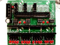
P4AC 4 axis controller by ljyang
...be mounted using the same holes as current stepper controllers on a makerbot.
it is all through hole soldering for easy assembly.
thingiverse
free
EXTRUDER 3DPRN -ES13- by 3DPRN
...uder can be used in these configurations:
1.direct
2.bowden
3.combinated with the second extruder in bowden
visit www.3dprn.com.
thingiverse
free
Ender 3 Extruder Stepper Support for chains. by Fl1pp3d0ff
...hether you're using the original extruder or not, and whether you've rotated your extruder 90 degrees (as i have) or not.
thingiverse
free
RepRapPro Mendel 9-Pin D-Type Connector Mount by ajayre
...ow the extruder so the entire hotend connection (bowden tube and electrical wiring) is connected in once place - at the extruder.
thingiverse
free
Ender 3 Max BLTouch Bracket and Marlin 2.0.7.2 firmware by riazshaikgp
...e you flash your board with the correct firmware. the bondtech extruder stepper unit size is 415 vs 93 for the standard extruder.
thingiverse
free
Anet A8 Titan Bowden Mount by boyleo
...s more compact and still easy to access the extruder.
note: you might need longer screws to attach the extruder with the stepper.
Jmcaz7
thingiverse
free
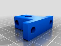
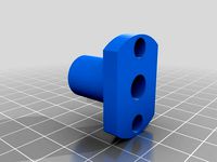
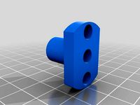
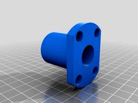
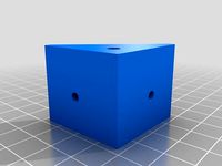
8mm Rod - Mounting Block by JMcAz7
...mcaz7
thingiverse
8mm rod mounting block. uses a 4mm cap head screw and nut for the pinch, and 6mm cap head screws for the base.
thingiverse
free
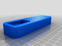
Dremel Tool Bit Organizer - Small by JMcAz7
...
i liked bosnianbill's dremel bit holder, but i didn't need on that big. here's a smaller version of the same thing.
thingiverse
free
LMH10UU - 10MM Flanged Linear Bearing - Oval Flange by JMcAz7
...these seem to be largely universal (at least among cheap chinese ebay sellers), but double check on your end if you use this. :-)
thingiverse
free
LMH8UU - 8MM Flanged Linear Bearing - Oval Flange by JMcAz7
...these seem to be largely universal (at least among cheap chinese ebay sellers), but double check on your end if you use this. :-)
thingiverse
free
LMH6UU - 6MM Flanged Linear Bearing - Oval Flange by JMcAz7
...these seem to be largely universal (at least among cheap chinese ebay sellers), but double check on your end if you use this. :-)
thingiverse
free
LMH16UU - 16MM Flanged Linear Bearing - Oval Flange by JMcAz7
...these seem to be largely universal (at least among cheap chinese ebay sellers), but double check on your end if you use this. :-)
thingiverse
free
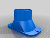
K40 Exhaust Vent - Slotted Mounts by JMcAz7
... didn't line. i didn't feel like getting super precise, so i just made it into a slotted mount that is working great. :-)
thingiverse
free
CTC Z-Axis-Stabilizer with 11mm OD bearing by JMcAz7
...yr for the original.
this fits the ctc, flashforge, and monoprice replicator clones (and probably other ones i didn't name).
thingiverse
free
Overhead Filament Spool Holder (Lulzbot Taz) - With Retaining Pin by JMcAz7
...ge that fits in the t-slot of the printer frame by 0.5mm since it seemed just a little bit too wide to drop into my frame easily.
thingiverse
free
3Dator Bowden Extruder- With Replicator/FlashForge/CTC Dual Extruder Bracket by JMcAz7
...ct with the stepper shaft and the base.
-i've created retainer loops to help keep the wiring in place and free of the spools.
Mightyboard
thingiverse
free
Makerbot Mightyboard by AnthonyM
...he page for the mighty board. we are currently referencing http://www.thingiverse.com/thing:16058 for the wonderful mighty board.
thingiverse
free

MightyBoard PinTool by tramalot
...l for removing the makerbot rep 1 mother board
sized for abs std profile
print 3 so you can leave two on the pins by the case
thingiverse
free
Mightyboard Adapter Plate With More Clearance by TypicalTitan
...pter plate with more clearance by typicaltitan
thingiverse
i just made it thinner to accommodate stepper drivers with heat sinks
thingiverse
free
MakerBot MightyBoard RevE by MakerBot
...)
designed by jeremy blum.
this is part of the makerbot replicator, which you can find at http://www.thingiverse.com/thing:18813
thingiverse
free
CTC LCD Case for MightyBoard LCD 2004 Controller Module Board by JulieJolly
...place it with this one instead. the old controller is not compatible with the geeetech new open source 3d printer control board.
thingiverse
free
Mightyboard rev h BTT SKR 1.4 turbo adapter by jifop
... rev h on a replicator 2x
simply screw the btt board with some 5 x m3 screws to the plate and clip it onto the original standoffs
thingiverse
free
Replicator MightyBoard Airflow Rework by garyacrowellsr
...e cooling airflow.
this thing re-routes the airflow of the original fan, and adds a location for a second fan.
updated 12/03/2012
thingiverse
free
CTC Mightyboard Standoff by jartz
...ast pic]
***note*** make sure you label all the connections before you remove them. ;-) it will make re-assembly much easier!!!
thingiverse
free
Replicator MightyBoard Protection Part 1 by garyacrowellsr
...ng it when installing your new board though.
this thing is part 1. in some following things, i hope to patch a few more holes.
thingiverse
free
Adapter to replace Mightyboard by cpertchik
...'ll update this post and keep you informed. i've posted the blender file for the truly adventurous to alter as they like.
Comprehensive
3d_ocean
$190
321 Comprehensive Building Materials Pack for C4D
...on description: this is all-in-one library of my building material series which contains 10 libraries. this comprehensive libr...
3d_export
$5

Carved ornamental 016
...for furniture facades or on the mirror frame... more comprehensive model allows you to use it in their projects,...
3d_export
$5

Carved ornamental 015
...for furniture facades or on the mirror frame... more comprehensive model allows you to use it in their projects,...
3d_export
$5

Carved ornamental 014
...for furniture facades or on the mirror frame... more comprehensive model allows you to use it in their projects,...
3d_ocean
$89

Chevrolet Tahoe 2010
...industry’s best-selling full-size suv . the new tahoe is comprehensivey redesigned and delivers a sharper, more precise driving feel,...
3d_export
$12
Carved ornamental 002
...used as a decorative element for furniture facades. more comprehensive model allows you to use it in their projects,...
3d_export
$6

Carved ornamental 003
...used as a decorative element for furniture facades. more comprehensive model allows you to use it in their projects,...
3d_export
free

Carved ornamental 001
...used as a decorative element for furniture facades. more comprehensive model allows you to use it in their projects,...
3d_ocean
$9

TRON Disks
...proud to introduce a low- poly rendition of the comprehensive identity disks of all the characters. set includes tron’s,...
3d_export
$5

Carved ornamental 005
...used as a decorative element for furniture facades. more comprehensive model allows you to use it in their projects,...
Ctc
turbosquid
$4

CTC Railroad Telephone
... available on turbo squid, the world's leading provider of digital 3d models for visualization, films, television, and games.
turbosquid
$7
Onibus Ciferal Padron Briza Volvo B58e CTC Azul
...briza volvo b58e ctc azul for download as blend, fbx, and obj on turbosquid: 3d models for games, architecture, videos. (1692482)
3dfindit
free
CTC
...ctc
3dfind.it
catalog: rcm
thingiverse
free
CTC by apone4
...ctc by apone4
thingiverse
modifica per ctc montaggio e3d
thingiverse
free
Filiamenthalter CTC by e2mars
...filiamenthalter ctc by e2mars
thingiverse
filiamenthalter ctc makebot
thingiverse
free
CTC's Feet by zion_taron
...ctc's feet by zion_taron
thingiverse
feet to ctc printers
thingiverse
free
CTC Abdeckung by Einstein77
...ctc abdeckung by einstein77
thingiverse
abdeckung für die hinteren bohrungen im gehäuse des ctc
thingiverse
free
CTC Corner caps by KyoFR
...ctc corner caps by kyofr
thingiverse
corner caps ctc
thingiverse
free
FILAMENT GUIDE CTC by HugoNogier
...filament guide ctc by hugonogier
thingiverse
filament guide ctc
thingiverse
free
CTC Bizer Fusshalter by FPV57
...ctc bizer fusshalter by fpv57
thingiverse
haltewinkel für gummifüsse ctc
Forge
archibase_planet
free
Forging
...forging archibase planet forge blank forging smithery forging n040908 - 3d model (*.gsm+*.3ds)...
archibase_planet
free

Forging
...forging archibase planet forging smithery forge blank forging n050210 - 3d model (*.gsm+*.3ds) for interior...
archibase_planet
free

Forging
...forging archibase planet forge blank forging smithery forging n240210 - 3d model (*.gsm+*.3ds)...
archibase_planet
free

Forging
...forging archibase planet forge piece forging smithery forging n160910 - 3d model (*.gsm+*.3ds)...
archibase_planet
free
Forging
...forging
archibase planet
forging
forging n180911 - 3d model (*.3ds) for interior 3d visualization.
archibase_planet
free

Forging
...forging
archibase planet
forging smithery
forging n290112 - 3d model (*.3ds) for interior 3d visualization.
archibase_planet
free

Forging
...forging
archibase planet
forging smithery
forging n030212 - 3d model (*.3ds) for interior 3d visualization.
archibase_planet
free

Forging
...forging
archibase planet
forging smithery
forging n270212 - 3d model (*.3ds) for exterior 3d visualization.
archibase_planet
free

Forging
...forging
archibase planet
forging smithery decoration
forging n281011 - 3d model (*.3ds) for interior 3d visualization.
archibase_planet
free

Forging
...forging
archibase planet
stair forging stairs
forging n140109 - 3d model (*.gsm+*.3ds) for interior 3d visualization.
Replicator
turbosquid
$5

Bucati USB Stick "replic"
... available on turbo squid, the world's leading provider of digital 3d models for visualization, films, television, and games.
3d_export
$75

3D Scania S730 8x4 Recovery SWS Edition
... of work with custom made parts to replicate the real truck unit<br>textures included<br>format available : obj files
3ddd
$1

Restoration Hardware - 1950s Dutch Shipyard Triple Shelving
...right to access the lofty upper shelves. crafted from solid walnut and iron, its antiqued finish replicates an aged, worn patina.
3d_export
$50

3D Scania Vabis 110 Model
...s 110 truck<br>very detailed and accurate replicated model<br>textures included<br>format available : obj files
3d_export
$11

Batman
...eled to replicate the original lego model to meet the highest quality , each part are arranged in hierarchy and parented objects.
3d_export
$85

3D Scania S730T Omars Recovery Truck Model
...ded<br>format available: obj file<br>on request,after purchase,i can offer other file formats the customer is in need
3d_ocean
$10

Star Wars: Anakin Skywalker Lightsaber
...tsaber of anakin skywalker. it contains a fairly high amount of polygons, suitable for semi-close up renders. main focus is it...
3d_ocean
$30

Ashley Jaidyn Poster Bedroom Set
...esser, mirror, chest. all models are made in compliance with the proportions and sizes of real furniture. with the replicated ...
3d_ocean
$10
Ashley Stages Chest
...w x 16”d x 49”h. material: wood products and other. color: replicated pine grain. this model is made in accordance with the pr...
3d_ocean
$6
Ashley Stages Table Lamp
...other. color: replicated pine grain. this model is made in accordance with the proportions and sizes of real furniture. the di...
Flash
3ddd
$1
Flash Magellan
...d
flash , magellan , полка
диван flash magellan
3ddd
$1

iluminacion flash
...luminacion flash
3ddd
iluminacion , flash
производитель: iluminacion
коллекция : flash
3d_export
$5

usb flash
...usb flash
3dexport
usb flash
3d_export
free
usb flash
...usb flash
3dexport
usb flash
3d_export
free
usb flash
...usb flash
3dexport
usb flash driver
turbosquid
$20
Flash
... available on turbo squid, the world's leading provider of digital 3d models for visualization, films, television, and games.
turbosquid
$9
Flash
... available on turbo squid, the world's leading provider of digital 3d models for visualization, films, television, and games.
3d_ocean
$5
Flash Drive
...h drive included : – materials – scene ( lighs / room ) – .c4d + .obj for any questions please feel free to contact me thank you.
3ddd
free
Кабинет руководителя FLASH
... стол , flash
кабинет руководителя flash (россия)
3d_export
$5

Flash 3D Model
...flash 3d model
3dexport
data usb flash
flash 3d model salip13 58303 3dexport
Ramps
turbosquid
$3
Kicker Ramp - Skate Ramp
...ramp - skate ramp for download as 3ds, obj, c4d, fbx, and dae on turbosquid: 3d models for games, architecture, videos. (1153575)
turbosquid
$2
Ramp
...squid
royalty free 3d model ramp for download as obj and fbx on turbosquid: 3d models for games, architecture, videos. (1494204)
turbosquid
$5

ramp
... available on turbo squid, the world's leading provider of digital 3d models for visualization, films, television, and games.
3d_export
$5
Ramp 3D Model
...ramp 3d model
3dexport
ramp jump carjump carramp car
ramp 3d model ryisnelly100 83186 3dexport
turbosquid
$10
Ramp and Barrels
...d
royalty free 3d model ramp and barrels for download as fbx on turbosquid: 3d models for games, architecture, videos. (1263040)
turbosquid
$19
Skate Ramp
...ty free 3d model skate ramp for download as dxf, obj, and fbx on turbosquid: 3d models for games, architecture, videos. (1187602)
turbosquid
$19
Skate Ramp
...ee 3d model skate ramp for download as dxf, obj, c4d, and fbx on turbosquid: 3d models for games, architecture, videos. (1187673)
turbosquid
$45
ramp door_center
... available on turbo squid, the world's leading provider of digital 3d models for visualization, films, television, and games.
turbosquid
$40
Ramp.3DS
... available on turbo squid, the world's leading provider of digital 3d models for visualization, films, television, and games.
turbosquid
$20
Skater Ramp
... available on turbo squid, the world's leading provider of digital 3d models for visualization, films, television, and games.
Conversion
3ddd
$1
Conversation Seat
...шетка
the conversation seat made in englandhttp://www.squintlimited.com/products/the_conversation_seat/gold
+ max 2011
3d_export
$10

Converse 3D Model
...converse 3d model
3dexport
converse shoe pc unix mac
converse 3d model electropainter17075 38067 3dexport
turbosquid
$100

converse-shoe
...quid
royalty free 3d model converse-shoe for download as c4d on turbosquid: 3d models for games, architecture, videos. (1398427)
turbosquid
$10

Conversation Furniture
... available on turbo squid, the world's leading provider of digital 3d models for visualization, films, television, and games.
turbosquid
$7

Converse Allstars
... available on turbo squid, the world's leading provider of digital 3d models for visualization, films, television, and games.
design_connected
$16
Conversation Club Chair
...conversation club chair
designconnected
donghia conversation club chair chairs computer generated 3d model. designed by n/a.
design_connected
$27

Hemicycle Conversation Chair
...rsation chair
designconnected
ligne roset hemicycle conversation chair computer generated 3d model. designed by nigro, philippe.
3d_export
$24

Converse keds 3D Model
...converse keds 3d model
3dexport
converse all star ked shoe clothes sports
converse keds 3d model vermi1ion 26201 3dexport
3ddd
$1

Converse All-Star Shoes
...converse all-star shoes
3ddd
кеды , обувь
converse all-star shoes
design_connected
$18

CONVERSE Jack Purcell Sneakers
...converse jack purcell sneakers
designconnected
converse jack purcell sneakers computer generated 3d model.
4
turbosquid
$9

Office Chair 4-4
... available on turbo squid, the world's leading provider of digital 3d models for visualization, films, television, and games.
3d_export
$5

doors- 4
...doors- 4
3dexport
doors 4
3d_export
$5
hinge 4
...hinge 4
3dexport
hinge 4
3ddd
$1

Штора №4
...штора №4
3ddd
штора №4
3d_export
free

playstation 4
...playstation 4
3dexport
playstation 4
turbosquid
$1

re 4-4 electric locomotive
... free 3d model re 4 4 electric locomotive for download as obj on turbosquid: 3d models for games, architecture, videos. (1707845)
3ddd
$1

nexus 4
...nexus 4
3ddd
lg , телефон
nexus 4
3ddd
$1
4 Poufs
...4 poufs
3ddd
пуф
4 soft poufs
turbosquid
$12

Calligraphic Digit 4 Number 4
...hic digit 4 number 4 for download as max, obj, fbx, and blend on turbosquid: 3d models for games, architecture, videos. (1389332)
3ddd
$1
Dauphin 4+
...dauphin 4+
3ddd
кресло
dauphin 4+ конференц кресло
1
turbosquid
$69

armchairs(1)(1)
... available on turbo squid, the world's leading provider of digital 3d models for visualization, films, television, and games.
turbosquid
$15
ring 1+1
... available on turbo squid, the world's leading provider of digital 3d models for visualization, films, television, and games.
turbosquid
$10

chair(1)(1)
... available on turbo squid, the world's leading provider of digital 3d models for visualization, films, television, and games.
turbosquid
$8

Chair(1)(1)
... available on turbo squid, the world's leading provider of digital 3d models for visualization, films, television, and games.
turbosquid
$2

RING 1(1)
... available on turbo squid, the world's leading provider of digital 3d models for visualization, films, television, and games.
turbosquid
$1

Table 1(1)
... available on turbo squid, the world's leading provider of digital 3d models for visualization, films, television, and games.
turbosquid
$1
house 1(1)
... available on turbo squid, the world's leading provider of digital 3d models for visualization, films, television, and games.
turbosquid
$59

Formula 1(1)
...lty free 3d model formula 1 for download as max, fbx, and obj on turbosquid: 3d models for games, architecture, videos. (1567088)
design_connected
$11
No 1
...no 1
designconnected
sibast no 1 computer generated 3d model. designed by sibast, helge.
turbosquid
$2
desert house(1)(1)
...3d model desert house(1)(1) for download as 3ds, max, and obj on turbosquid: 3d models for games, architecture, videos. (1055095)