Thingiverse

Remixed Left Case by pigaro
by Thingiverse
Last crawled date: 3 years, 1 month ago
This is yet another remix of the excellent Teaching Tech Ender 3 all-in-one electronics left case. The changes for this case include a different DC-DC converter and relay module from the ones used in the original design. The DC-DC converter is a DZS Elec model number Super LM2596S, 9 – 36 V input, 5.2 V output up to 6 A (depending on input voltage). The DC-DC converter has both a USB-A connector and a wire output. I used a USB-A to USB-C right angle (both ends) cable to provide power to the Raspberry Pi 4B. I used the wire connectors to power a 5 V Nocturna NF-A4x20 fan. The choice of parts allowed me to put this together without soldering, although connecting to the relay might have been easier if the wires had been tinned.
The DC-DC converter fits into a well and is not attached to the case. The reason for this is that it allows the converter to be removed (without disconnecting any wires) to provide access to the micro SD slot of the Raspberry Pi. Access is not easy, but I have been able to remove and install the micro SD card. Be careful – I broke one card.
I used a USB-A to USB-C cable that had right angle ends (UGREEN). I would recommend a right angle end on at least the Raspberry Pi side (micro USB for Raspberry Pi versions 3 or less, USB-C for version 4). There might be enough space for a regular connector on the USB-A side, depending on the bend radius of the cable. The shortest cable was 1.5 feet, which is way too long and needed to be coiled.
The relay module is a HiLetgo 5 V, one-channel relay, model 3-01--340, with a different footprint than the original design. I only included one relay to control 24 V power to the printer side. I don't think a second relay would fit. Note that I had to leave off one of the four screws due to interference with the USB cable.
Getting all the wires in was a tight fit, and the wire I used for the relay was probably too fine (high gauge) and difficult for the relay connector to clamp. I wired the DC-DC converter directly to one set of unused connectors in the power supply, so the Raspberry Pi is powered whenever the power switch is on.
One other change to the original design was to provide through holes for the Raspberry Pi and relay screw mounts. The M3x8 mm screws bottomed out before contacting the circuit boards. Adding a hole though the case allowed the screws to tighten to the board and they only protrude slightly through the case. I had the opposite problem on the right side case. The screws protruded too far, so I made some cylinders to offset the screws.
Similar models
thingiverse
free

Raspberry Pi B+ LulzBot TAZ 4 Case/Extension by pavelkaroukin
... source in the right bottom corner - see picture. make sure to use correct polarity, as i believe incorrect one might damage rpi.
thingiverse
free

Anet A8 Electronics Case (Raspberry Pi Zero (W), DC Converter + Mainboard) by miege95
....
dc converter: https://www.ebay.de/sch/i.html?_from=r40&_sacat=0&_nkw=dc+dc+converter+module+12+v+to+5v+3a+15w+duble+usb
thingiverse
free

Raspberry Pi case for 3D printer by demolitions
...sb connector for power (will upload photos), a raspberry pi (i used a pi 3 model b), and a kuman 3.5" touchscreen (mpi3508).
thingiverse
free

USB Buck Power Converter Casing by dermdaly
... buck converter
note: the fit is very tight, but once the buck converter is in place, it is very snug an won't rattle around.
thingiverse
free

Anet A8 - Raspberry pi right side mount by Keepars
... to mount my raspberry pi close to my power supply so i can access the relays controlling my lights and the power of the printer.
thingiverse
free

Raspberry Pi 7" touchscreen case and mounting by KDan
...e squeezing the top and bottom of the case. once one side is disengaged, just slide to the other side and it will come right off.
thingiverse
free

Raspberry Pi Zero (W) Case for Right Angle Female Pin Header by marian42
...ports and the pin headers. the pin headers are similar to this one: https://www.adafruit.com/product/2823 requires two m3x6 screws and...
thingiverse
free

Anet A8 PSU cover with switch, relays, fan and OctoPrint
...additional details) one power switch (note: there are two similar versions of this switch, one with countersink screw heads...
thingiverse
free

Prusa Raspberry Pi 4 B Power Supply by Jam007
...-zasilacz-model/dp/b07tz89bt7
angled usb c: https://www.aliexpress.com/item/33051776040.html?spm=a2g0s.9042311.0.0.51304c4d0wo6ls
thingiverse
free

Raspberry Pi 7" Display Case
...a space on the right hand side for a panel mount usb socket and an aperture at the back for the power cable and any other cables.
Pigaro
3ddd
$1

92657 EGLO PIGARO
... pigaro
диаметр - 37 см.
высота - 110 см.
мощность - 1х60вт e27.
материалы - сталь, белый / сталь, кристал, белый,прозрачный
3d_sky
free

92657 EGLO PIGARO
...aro
3dsky
eglo
diameter - 37 cm height - 110 cm power - 1h60vt e27. materials - steel, white / steel, crystal, white, transparent
thingiverse
free

Atlas V 400 Series by pigaro
...rocket boosters (srbs), a centaur upper stage with either a smooth or ribbed interstage, and choice of lpf, epf, or xepf fairing.
thingiverse
free

Treble Hook Snell Holder by pigaro
... 14 (these are the only sizes i have).
large - size 2 or 4
medium - size 6 or 8
small - size 10 or 12
tiny - size 14 and maybe 16
thingiverse
free

3D Printer Tool Holder by pigaro
...wo plier-like tools, four small files (rectangular flat, rat-tail, triangular, and half-round, and a small magnetic pick-up tool.
thingiverse
free

Treble Hook Snell Tool by pigaro
...ium - size 6 or 8
small - size 10 or 12
tiny - size 14 and maybe 16 (i don't have any 16)
this was designed using fusion 360.
thingiverse
free

Clip-in Printer Bed Light by pigaro
...nal design was without a light shade, but after using it i decided the shade was a good idea.
this should print without supports.
thingiverse
free

Snap-in V-slot Covers for Ender 3 Power Supply Rail by pigaro
... are sized for an ender 3. the cover with the hole at 29 mm goes on the top, the cover with the hole at 79 mm goes on the bottom.
thingiverse
free

Ender 3 (non-Pro) Extended Dual Drawers by pigaro
...at printer has a wider center extrusion (40 mm instead of 20 mm).
the case and drawers should print as they are with no supports.
Left
3d_export
$7

human-left-hand
...human-left-hand
3dexport
human-left-hand
3d_export
$5

Left arrrow 3D Model
...left arrrow 3d model
3dexport
left turn sign signal signage direction
left arrrow 3d model ryisnelly100 88746 3dexport
design_connected
$20

Nomade Chaise Left
... chaise left
designconnected
ligne roset nomade chaise left lounge chairs computer generated 3d model. designed by didier gomez.
design_connected
$16

Feng Chaise Left
...ng chaise left
designconnected
ligne roset feng chaise left lounge chairs computer generated 3d model. designed by didier gomez.
3ddd
$1

Vittorio-Left facing Sofa
...vittorio-left facing sofa
3ddd
vittorio , угловой
vittorio-left facing sofa
turbosquid
$33

Left Turn Sign
...ree 3d model left turn sign for download as 3ds, max, and obj on turbosquid: 3d models for games, architecture, videos. (1303404)
turbosquid
$15

Left-handed dagger
... available on turbo squid, the world's leading provider of digital 3d models for visualization, films, television, and games.
turbosquid
$10

no left turn - 3ds
... available on turbo squid, the world's leading provider of digital 3d models for visualization, films, television, and games.
turbosquid
$7

Left Arm Armour
... available on turbo squid, the world's leading provider of digital 3d models for visualization, films, television, and games.
turbosquid
$5

Pass Left Signs
... available on turbo squid, the world's leading provider of digital 3d models for visualization, films, television, and games.
Remixed
turbosquid
$5
MODA Collection Remix Chair
... available on turbo squid, the world's leading provider of digital 3d models for visualization, films, television, and games.
3d_export
$12
remix yamaha rm1x
...remix yamaha rm1x
3dexport
geometry triangles 15.2k vertices 7.6k pbr no textures 1 materials 1 uv layers yes
3d_ocean
$5
Vray fabric Kvadrat remix green - tileable
...th vray and 3dsmax. high-resolution texture images (2000×2000 px) file included: shader vray 2.40 texture image 3ds max 2011 file
turbosquid
$20
Gerrit Rietveld 1938 Zig Zag Chair Remix
... available on turbo squid, the world's leading provider of digital 3d models for visualization, films, television, and games.
3d_export
$10

multicolored remix parametric table furniture
... fbx, obj, mtl, archive with textures. the model has no glitches. render and materials - vray . without using plugins. good use!
3ddd
$1
Barovier&Toso / Manhattan Remix 7192
... 004293-142405
в коллекции есть люстры 7, 9, 12 рожковые. диаметр соответственный 1000, 1250, 1500 мм.
3ddd
$1
Muuto fiber chair
...ture/black, nature/oak, remix 133/grey, remix 183/black, remix 643/dusty red, black silk leather/black, cognac silk leather/black
3ddd
$1
Barovier&Toso 7190-7195
...лочнай люстра фабрики barovier&toso;, коллекция manhattan remix, артикул 7190-7195.
размеры в inches: 39" 1/2wх26"h
3d_export
$5
3D Locking Handle Weatherproof Storage Box Container
...handle weatherproof storage box container 3dexport new, improved and remixed no screws required. print-in-place. weatherproof. parametric. 2 parts. easy...
cg_studio
$49
HTC One Mini 2 Amber Gold3d model
...bj .mb .lwo .fbx .c4d .3ds - htc one mini 2 amber gold 3d model, royalty free license available, instant download after purchase.
Case
3d_export
$1
case
...case
3dexport
case
archibase_planet
free
Case
...case
archibase planet
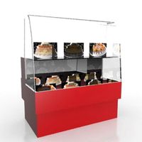
showcase show-case glass case
glass-case + cakes - 3d model for interior 3d visualization.
archibase_planet
free
Case
...case
archibase planet
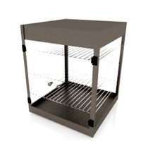
showcase show-case glass case
glass-case for chips - 3d model for interior 3d visualization.
archibase_planet
free
Case
...case
archibase planet
case shelving drawer
case - 3d model for interior 3d visualization.
archibase_planet
free
Case
...case
archibase planet
case rack locker
case - 3d model for interior 3d visualization.
archibase_planet
free
Case
...case
archibase planet
case drawer kitchen furniture
case - 3d model for interior 3d visualization.
archibase_planet
free
Case
...case
archibase planet
case cupboard shelving
glass case - 3d model for interior 3d visualization.
archibase_planet
free
Case
...case
archibase planet
case handbag suitcase
case - 3d model (*.gsm+*.3ds) for interior 3d visualization.
archibase_planet
free
Case
...case
archibase planet
case suitcase
case 5 - 3d model (*.gsm+*.3ds) for interior 3d visualization.
archibase_planet
free
Case
...case
archibase planet
locker case dresser
case - 3d model (*.gsm+*.3ds) for interior 3d visualization.