Thingiverse

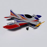
RC Airboat for water, ice and snow
by Thingiverse
Last crawled date: 4 years, 2 months ago
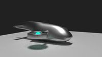
Source codes for a 3D printed radio controlled airboat.
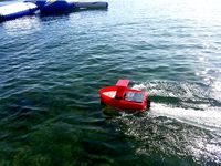
It is very fast and challenging to control on ice and packed snow, with limited
directional stability. Expect a lot of fun and excitement. It is fast enough and
more stable on water. My version does not glide well on grass.
Please see also gitlab repository for more details
Jan Kybic, kybic@fel.cvut.cz
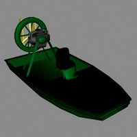
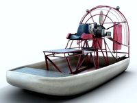
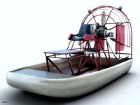
Description
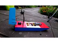
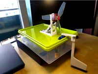
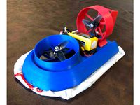
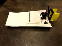
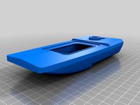
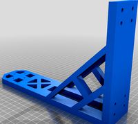
It has a push configuration propeller and twin air rudders controled by a servo.
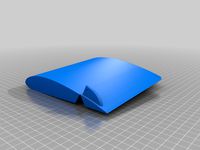
It is 200mm wide and 200mm long, the hull is designed to be printed in two main
pieces, each about 200mm times 200mm big. The printed hull weights about 650g,
the complete airboat ready to run including battery about 950g. It might be
possible to make it lighter at the expense of some rigidity.
Equipment
You will need your own receiver, battery, ESC,
motor, push propeller (diameter around 135mm) and a micro servo (such as this.
I salvaged my electronics from a broken Hobby King Floater
Jet plane,
including a 3S (12V) Lipoly battery. An ESC capable of reversing is useful but
not necessary. The mounting pod for the motor has four holes regularly spaced on
a circle with diameter 23.5mm.
Compiling
The model is programmed designed in
[SolidPython] (https://github.com/SolidCode/SolidPython). Running theairboat.py produces several files: (airboat.scad, cover.scad, motor_beam.scad,
rear.scad, rudder_left.scad, connector_pin.scad, front.scad, rudder_beam.scad,
rudder_right.scad) which you compile using [OpenSCAD] (https://www.openscad.org/)
to produce '.stl' files, which you in turn run through your favorite slicer
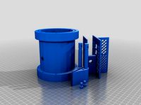
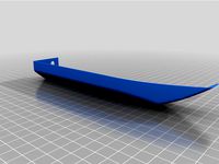
program as usual. The front part of the hull is printed vertically with 1% infill, 3
perimeters and 4 top and bottom layers. The rear part is printed horizontally
with 5% infill. In critical areas (under the connector pin holes, the servo, and
the cable holes), the infill is manually increased to 15% to support bridging.
The cover lid is printed with 15% infill and the remaining pieces (connectors,
rudders and beams) with 5 perimeters and 40% infill.
I printed the two pieces of the hull, the two rudders, and the four connecting
pins in PETG. The two bars holding the motor and the rudders were printed in ABS
but PETG would be probably also fine. The electronic compartment cover lid is
also printed in PETG - I originally wanted to print it in FLEX but failed so far.
To print everything takes about 22 hours with a 0.6mm nozzle and 0.35mm layers.
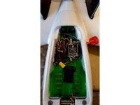
Building
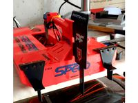
The two hull pieces are connected with the 4 connector pins and glued together
by epoxy. I spray painted the hull by a plastic primer and several layers of red
acrylic paint. The servo and the two beams are inserted and motor is mounted. Paper
clip wire is used as the top shaft for the rudders and as the link between the
servos and the rudder horns. When the servo is adjusted, attach it by a screw
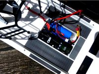
and seal with hot glue or silicone. The motor cables are attached to the beam by cable
ties. When the motor and servo cables are thread through the holes, the holes
can be sealed by a hot glue or silicone. I mount the receiver, ESC and battery
by a Velcro tape attached by a hot glue. It is better to mount the electronics
on the walls in case some water gets through.
It is very fast and challenging to control on ice and packed snow, with limited
directional stability. Expect a lot of fun and excitement. It is fast enough and
more stable on water. My version does not glide well on grass.
Please see also gitlab repository for more details
Jan Kybic, kybic@fel.cvut.cz
Description
It has a push configuration propeller and twin air rudders controled by a servo.
It is 200mm wide and 200mm long, the hull is designed to be printed in two main
pieces, each about 200mm times 200mm big. The printed hull weights about 650g,
the complete airboat ready to run including battery about 950g. It might be
possible to make it lighter at the expense of some rigidity.
Equipment
You will need your own receiver, battery, ESC,
motor, push propeller (diameter around 135mm) and a micro servo (such as this.
I salvaged my electronics from a broken Hobby King Floater
Jet plane,
including a 3S (12V) Lipoly battery. An ESC capable of reversing is useful but
not necessary. The mounting pod for the motor has four holes regularly spaced on
a circle with diameter 23.5mm.
Compiling
The model is programmed designed in
[SolidPython] (https://github.com/SolidCode/SolidPython). Running theairboat.py produces several files: (airboat.scad, cover.scad, motor_beam.scad,
rear.scad, rudder_left.scad, connector_pin.scad, front.scad, rudder_beam.scad,
rudder_right.scad) which you compile using [OpenSCAD] (https://www.openscad.org/)
to produce '.stl' files, which you in turn run through your favorite slicer
program as usual. The front part of the hull is printed vertically with 1% infill, 3
perimeters and 4 top and bottom layers. The rear part is printed horizontally
with 5% infill. In critical areas (under the connector pin holes, the servo, and
the cable holes), the infill is manually increased to 15% to support bridging.
The cover lid is printed with 15% infill and the remaining pieces (connectors,
rudders and beams) with 5 perimeters and 40% infill.
I printed the two pieces of the hull, the two rudders, and the four connecting
pins in PETG. The two bars holding the motor and the rudders were printed in ABS
but PETG would be probably also fine. The electronic compartment cover lid is
also printed in PETG - I originally wanted to print it in FLEX but failed so far.
To print everything takes about 22 hours with a 0.6mm nozzle and 0.35mm layers.
Building
The two hull pieces are connected with the 4 connector pins and glued together
by epoxy. I spray painted the hull by a plastic primer and several layers of red
acrylic paint. The servo and the two beams are inserted and motor is mounted. Paper
clip wire is used as the top shaft for the rudders and as the link between the
servos and the rudder horns. When the servo is adjusted, attach it by a screw
and seal with hot glue or silicone. The motor cables are attached to the beam by cable
ties. When the motor and servo cables are thread through the holes, the holes
can be sealed by a hot glue or silicone. I mount the receiver, ESC and battery
by a Velcro tape attached by a hot glue. It is better to mount the electronics
on the walls in case some water gets through.
Similar models
thingiverse
free
Airboat rudder by dlacko
...using plywood, meccano and standard rc parts (9g servo, brushless motor + esc, lipo battery, turnigy 9x transmitter and receiver)
thingiverse
free
Servo airboat rudder by dudufreeride
...l holes to choose the depth of the rudder in the water.
tip: using a drop of hot glue on the servo arm prevents it from detaching
thingiverse
free
Simple Brushless RC Sport Hovercraft by Sir_Lancelot178
...radio.
note: moving the center of gravity around will change how it turns and handles. experiment until you find what works best.
thingiverse
free
ROV v3 by Turretboy
...ra and possible gimble
2) main hull is for batteries, servos (rudder), esc's and receiver.
3) rear will be for motor assembly
thingiverse
free
Gartt airboat servo tray by Jmzwiers
... stay dry when some water enters the servo bay. also much more space for the battery and easy access and changing of the battery.
thingiverse
free
High-Speed Planing RC Boat by awseiger
...l the cable holes in with hot glue or epoxy. i recommend hot glue, as it can be re-heated to allow for replacement of the motors.
thingiverse
free

Servo Motor Mount SG90
...ount. the motor fits snuggly into the mount. hot glue the outside of mount to the surface you are wanting to install the servo.
thingiverse
free
Adjustable Thrust Angle Airboat by Setesh2000
... the boat performs.
i included 2 extra back plates, one with only one esc heat sink hole, one with none so it can be customized.
thingiverse
free
slow poke mini rc plane
...i rc plane
thingiverse
foam board rudder and elevator with elastic bands to hold it on or hot glue ,hot glue for servo and motor
thingiverse
free
ZOHD_DART Battery flight controller gps Immortal T by spaners
...l t mount.
battery tray petg 50% infill
gps mount petg 50% infill
antenna mount tpu 50% infill and supports
use hot glue to mount
Airboat
turbosquid
$10
AIRBOAT.3DS
... available on turbo squid, the world's leading provider of digital 3d models for visualization, films, television, and games.
3d_export
$99
Airboat 3D Model
...verglades louisiana engine motor fan fishing recreational alligator bayou propeller
airboat 3d model dzejsi.models 72673 3dexport
cg_studio
$99
Airboat3d model
...odel
cgstudio
.3ds .fbx .lwo .lxo .max .obj - airboat 3d model, royalty free license available, instant download after purchase.
3d_export
$10
Electric Boat
...transport of the future. my model is a rubber airboat in the bow part of which there are 3...
thingiverse
free

Airboat meeple by willssweetescape
...airboat meeple by willssweetescape
thingiverse
this is a simple airboat meeple i designed for a fellow game designer.
thingiverse
free
Airboat
...te control : 2 - 3ch
brushless motor 1806
esc 10a-25a
li-polymer 2-3s
9 grams servo
20mm x 2mm o-ring x 1.
14mm x 2mm o-ring x 2.
thingiverse
free
Airboat skid plates by josiaht04
...airboat skid plates by josiaht04
thingiverse
skid plates for airboat for added protection
thingiverse
free
Extended Rudder for Airboat by Renngarage
...ization fins are not in the intention of an airboat but - hey - if it works - on the water at least.
https://youtu.be/ut9wtrccw7y
thingiverse
free
Airboat motor mount by Aaron370150
...airboat motor mount by aaron370150
thingiverse
thingiverse
free
Airboat rudder by dlacko
...using plywood, meccano and standard rc parts (9g servo, brushless motor + esc, lipo battery, turnigy 9x transmitter and receiver)
Snow
design_connected
$11
Snow
...snow
designconnected
swedese möbler ab snow coffee tables computer generated 3d model. designed by nendo.
turbosquid
$6
Snow
...ow
turbosquid
royalty free 3d model snow for download as max on turbosquid: 3d models for games, architecture, videos. (1215363)
3d_export
$5

House in the snow
...house in the snow
3dexport
house in the snow
3d_ocean
$2

Snow
...ly snow stylized white winter
this is a hand painted, tiling texture for clumped snow. it is a single 512×512 png texture. enjoy!
3d_export
$5

snow flake
...snow flake
3dexport
snow flake ornament
3d_export
$5

snow globe
...snow globe
3dexport
snow ball made in blender
turbosquid
$5
Snow
... available on turbo squid, the world's leading provider of digital 3d models for visualization, films, television, and games.
3d_export
$65

snowing
...snowing
3dexport
simple rendering of the scene file
3d_ocean
$2
Snow
...nted texture tga
this is a tile able, hand painted snow texture tile. included is one versions at 512×512 pixels in .tga format.
3d_ocean
$12
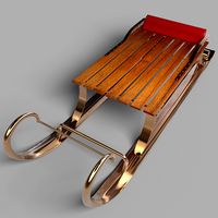
Snow Sled
...led
3docean
sledge sledging sleg sleigh snow winter
snow sled 3d model – .max file | .obj file | v-ray 2.4 | textures | materials
Ice
3d_export
$19

Cartoon Iceberg Ice Cave sea surface Snow Mountain ice ice surface sea ice cone Ice Cave gla
...on iceberg, ice cave, sea surface, snow mountain, ice, ice surface, sea ice cone, ice cave, glacier 2.files include 3dmax fbx obj
3d_export
$19

Cartoon Iceberg Ice Cave sea surface Snow Mountain ice ice surface sea ice cone Ice Cave gla
...on iceberg, ice cave, sea surface, snow mountain, ice, ice surface, sea ice cone, ice cave, glacier 2.files include 3dmax fbx obj
3d_ocean
$2
Ice
...snow texture tile
this is a tile able, hand painted ice texture tile. included is one versions at 512×512 pixels in .tga format.
3d_ocean
$2
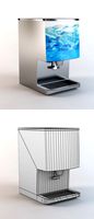
Ice Dispenser
...cooler
ice dispenser model in 3ds max. you can see this machine in soft drink shop, super market, hypermarket and some fast food.
3d_export
$5

Ice cream
...ice cream
3dexport
ice crice
3d_export
free

Donut with icing
...donut with icing
3dexport
donut with icing
3d_ocean
$3
ice cubes
...ice cubes
3docean
coke cube ice soda beverage
3d model and shader of ice cubes
3d_export
$12

ice cream
...ice cream
3dexport
ice cream, made in blender
3d_export
free

Ice box
...ice box
3dexport
it is a ice box as shown in the pictures.
3d_ocean
$2

Ice Texture
...al freeze frost frozen frozen water ice icey snow winter
the texture of the ice / ice surface. files included: tga and jpg files.
Rc
3ddd
$1
RC Helicopter
...rc helicopter
3ddd
вертолет
mini rc helicopter
93.329 polys
3d_export
$7
rc helicopter model
...rc helicopter model
3dexport
rc helicopter model
3d_ocean
$25
RC F1
...rc f1
3docean
auto car control f1 formula race rc remote speed
remote control f1 car
turbosquid
$10
rc plane
...lane
turbosquid
free 3d model rc plane for download as blend on turbosquid: 3d models for games, architecture, videos. (1295828)
turbosquid
$100
RC Helicopter
...free 3d model rc helicopter for download as 3ds, max, and obj on turbosquid: 3d models for games, architecture, videos. (1298511)
turbosquid
$75
RC buggy
... available on turbo squid, the world's leading provider of digital 3d models for visualization, films, television, and games.
turbosquid
$30
RC Jet
... available on turbo squid, the world's leading provider of digital 3d models for visualization, films, television, and games.
turbosquid
$30
Rc airplane
... available on turbo squid, the world's leading provider of digital 3d models for visualization, films, television, and games.
turbosquid
$10
RC-Car
... available on turbo squid, the world's leading provider of digital 3d models for visualization, films, television, and games.
turbosquid
$8
RC Airfield
... available on turbo squid, the world's leading provider of digital 3d models for visualization, films, television, and games.
Water
turbosquid
$2
water bin water tank
...e 3d model water bin water tank for download as blend and obj on turbosquid: 3d models for games, architecture, videos. (1594026)
archibase_planet
free
Water purifier
... purifier water purification water treatment
water purifier n050914 - 3d model (*.gsm+*.3ds+*.max) for interior 3d visualization.
3d_ocean
$6
glass water
...glass water
3docean
clear glass glass water
glass filled with water
3ddd
$1

Watering pot
...watering pot
3ddd
watering pot лейка поливалка , лейка
watering pot
3d_ocean
$12
Water Dispenser
...dispenser furnishings lowpoly water
this is a water dispenser hot water for tea is winter and summer is cold for souls. have fun!
3d_ocean
$2
Water
...water
3docean
this is a tile able, hand painted water texture tile. included is one versions at 512×512 pixels in .tga format.
3d_export
$6
water tanker
...water tanker
3dexport
water tanker
3d_export
$6
water bottle
...water bottle
3dexport
water bottle
3d_export
$5
water bottle
...water bottle
3dexport
water bottle
3d_export
$5

water thermos
...water thermos
3dexport
water thermos