GrabCAD
RASSOR_Challenge_Mikel_Iturbe
by GrabCAD
Last crawled date: 1 year, 10 months ago
HOW THE DESIGN WORKS AND INTENDED FILL RATIO
a) How the design works
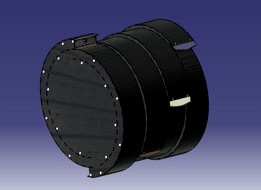
The present RASSOR design has four drums with two scoops each of them. Each drum differs 45 degrees from the other. Therefore, at any given time only one or two scoops are engaged in the regolith in order to keep the low reaction forces of the actual RASSOR design developed by NASA.
Each drum has two channels through which the regolith goes in and out during loading and unloading, respectively. These channels exceed the 180 degrees with constant distance among the walls (to avoid possible clogging) so by the time the lower scoop has captured a specific amount of lunar regolith and it is going up again, the mass inside the drum does not fall out through the upper scoop when it reaches an inclination that would unload the regolith inside the drum.
The process described to load lunar regolith within the present design is only possible if there are two channels per drum and if each drum has no inner connection with the other drums when holding material inside.
Due to the large channels that exceed 180 degrees and the clogging problems in the scoops addressed during testing phases of the 1st RASSOR design a structured roughness surface has been incorporated, see figure attached, to the walls of the channels as a passive solution to avoid possible clogging scenarios. As defined in [1] a structured roughness surface has a strong impact in avoiding possible clogging situations due to the shear stress produced by this type of surface. “Findings demonstrate the importance of the shear stress on the propensity of tapered channels to clog. The higher shear stresses inhibit the attachment of particles to the channel walls, thereby delaying channel clogging caused by particle build up at the channel walls” [2].
b) Intended fill ratio
The total area of each drum is 0,134m2 and the width of the scoops/channels is 85,5mm. This gives us a total volume of 11,547 litres per drum.
The intended area to be filled has a diameter of 351mm as shown in the image attached. Therefore, the intended volume to be captured would be approximately 8,273 liters/drum. (Considering that the width of the scoops/channels is 85,5mm)
Fill ratio = (8,273/11,547) x 100 = 71,6%
Total Volume intended to be captured = 4 Drums x 8,273 l/Drum = 33.092 liters
IS THE DESIGN REAL? CAN THE DESIGN WORK? CAN IT ACTUALLY BE CREATED?
The present RASSOR design uses Aluminium sheet metal for the scoops with a density of 2640 kg/m3. Bolts and nuts are intended to be made from carbon fiber with a density of 1500 kg/m3. The main structures and taps of the design are intended to be built with polymer matrix composites [3] which densities can vary from 1100kg/m3 to 1700kg/m3. For the present design, a density of 1200kg/m3 has been used.
The total mass of the current bucket drum is 4.838Kg
DIMENSION REQUIREMENTS
See blueprint attached
SIMULATION
A short simulation has been carried out with EDEM (A discrete element method software) in order to check the loading and unloading process of the present design. See figures attached in their respective folder “RASSOR Simulation_Images”. The simulation time was a critical parameter to consider in order to end up with some results for the simulation.11 seconds of simulation have been captured to show how the design works. From second 5 to second 10 the design works in a loading mode. From second 10 onwards the design works in an unloading mode.
REFERENCES
[1] MARTINEZ, A; DAVID FROST, J; THE INFLUENCE OF SURFACE ROUGHNESS FORM ON THE STRENGTH OF SAND–STRUCTURE INTERFACES, MARCH 2017, DOI: 10.1680/JGELE.16.00169
[2] SORELL , S MASSENBURG; · ESTHER AMSTAD; · DAVID A. WEITZ; CLOGGING IN PARALLELIZED TAPERED MICROFLUIDIC CHANNELS, JUNE 2016, DOI 10.1007/S10404-016-1758-6
[3] BURYACHENKO, V; MICROMECHANICS OF HETEROGENEOUS MATERIALS, 2007, SPRINGER PUBLISHING COMPANY, 1ST EDITION
a) How the design works
The present RASSOR design has four drums with two scoops each of them. Each drum differs 45 degrees from the other. Therefore, at any given time only one or two scoops are engaged in the regolith in order to keep the low reaction forces of the actual RASSOR design developed by NASA.
Each drum has two channels through which the regolith goes in and out during loading and unloading, respectively. These channels exceed the 180 degrees with constant distance among the walls (to avoid possible clogging) so by the time the lower scoop has captured a specific amount of lunar regolith and it is going up again, the mass inside the drum does not fall out through the upper scoop when it reaches an inclination that would unload the regolith inside the drum.
The process described to load lunar regolith within the present design is only possible if there are two channels per drum and if each drum has no inner connection with the other drums when holding material inside.
Due to the large channels that exceed 180 degrees and the clogging problems in the scoops addressed during testing phases of the 1st RASSOR design a structured roughness surface has been incorporated, see figure attached, to the walls of the channels as a passive solution to avoid possible clogging scenarios. As defined in [1] a structured roughness surface has a strong impact in avoiding possible clogging situations due to the shear stress produced by this type of surface. “Findings demonstrate the importance of the shear stress on the propensity of tapered channels to clog. The higher shear stresses inhibit the attachment of particles to the channel walls, thereby delaying channel clogging caused by particle build up at the channel walls” [2].
b) Intended fill ratio
The total area of each drum is 0,134m2 and the width of the scoops/channels is 85,5mm. This gives us a total volume of 11,547 litres per drum.
The intended area to be filled has a diameter of 351mm as shown in the image attached. Therefore, the intended volume to be captured would be approximately 8,273 liters/drum. (Considering that the width of the scoops/channels is 85,5mm)
Fill ratio = (8,273/11,547) x 100 = 71,6%
Total Volume intended to be captured = 4 Drums x 8,273 l/Drum = 33.092 liters
IS THE DESIGN REAL? CAN THE DESIGN WORK? CAN IT ACTUALLY BE CREATED?
The present RASSOR design uses Aluminium sheet metal for the scoops with a density of 2640 kg/m3. Bolts and nuts are intended to be made from carbon fiber with a density of 1500 kg/m3. The main structures and taps of the design are intended to be built with polymer matrix composites [3] which densities can vary from 1100kg/m3 to 1700kg/m3. For the present design, a density of 1200kg/m3 has been used.
The total mass of the current bucket drum is 4.838Kg
DIMENSION REQUIREMENTS
See blueprint attached
SIMULATION
A short simulation has been carried out with EDEM (A discrete element method software) in order to check the loading and unloading process of the present design. See figures attached in their respective folder “RASSOR Simulation_Images”. The simulation time was a critical parameter to consider in order to end up with some results for the simulation.11 seconds of simulation have been captured to show how the design works. From second 5 to second 10 the design works in a loading mode. From second 10 onwards the design works in an unloading mode.
REFERENCES
[1] MARTINEZ, A; DAVID FROST, J; THE INFLUENCE OF SURFACE ROUGHNESS FORM ON THE STRENGTH OF SAND–STRUCTURE INTERFACES, MARCH 2017, DOI: 10.1680/JGELE.16.00169
[2] SORELL , S MASSENBURG; · ESTHER AMSTAD; · DAVID A. WEITZ; CLOGGING IN PARALLELIZED TAPERED MICROFLUIDIC CHANNELS, JUNE 2016, DOI 10.1007/S10404-016-1758-6
[3] BURYACHENKO, V; MICROMECHANICS OF HETEROGENEOUS MATERIALS, 2007, SPRINGER PUBLISHING COMPANY, 1ST EDITION
Similar models
grabcad
free

EVN Flap Drum
...epresents an average fill ratio of 70%. 10s is needed to dump the entirety of the contained regolith.
i hope you will apreciate.
grabcad
free

NASA RASSOR "Chum Bucket"
... be cnc milled. these parts can then be welded together to create one solid part.
4. the design meets all dimension requirements.
grabcad
free

RASSOR Bucket Drum Design
...0 mm
volume of regolith captured: approximately 19 liters
fill ratio: approximately 70%
materials:
cfrp
5052-h38 aluminium alloy
grabcad
free

NASA (RASSOR) Bucket Drum Design Challenge with Design VPR 21
...ely for blades and bucket
7. inside section view while filling bucket
8. section view of one from 16 modified 623zz ball bearings
grabcad
free

RASSOR
...ith an 87% fill ratio. the design also has a diameter of 450mm and a length of 360mm, all fitting within the design requirements.
grabcad
free

Trapezoidal Drum
...e is no moving part inside or outside except the entire drum itself which rotates.
please, do read the file conceptual_draft.pdf.
grabcad
free

NASA RASSOR Drum Bucket
...only be estimated to about 65 %.
material: polyether ether petone (peek)
manufacturing: selective laser sintering
mass: ~4.95 kg
grabcad
free

RASSOR Bucket
...for unloading the drum will rotate in reverse direction which will allow the regolith to follow the spiral path towards the exit.
grabcad
free

NASA RASSOR Spiral Drum
...erial: ti 6al 4v
mass: 2.6 kg
drum length: 348mm
drum diameter: 450mm
engaged scoop width: 172mm
max captured regolith: 33 liters
grabcad
free

RASSOR-Casement cover
...et drum diameter: 450 mm
bucket drum length: 360 mm
volume of regolith captured: 41.16 liters (permissible volume 72%)
thank you
Mikel
turbosquid
$7
MIKEL WHELCH CURVE CHAIR 2020 Collection 3D model
...elch curve chair 2020 collection 3d model for download as max on turbosquid: 3d models for games, architecture, videos. (1616568)
thingiverse
free

mikel key chain by papasmurf76
...mikel key chain by papasmurf76
thingiverse
this is an amibigram for mikel that is mikel both ways
thingiverse
free
Beeper Holder by mikeller
...beeper holder by mikeller
thingiverse
beeper holder for a 9.5mm beeper. fits onto an m3 standoff.
thingiverse
free
VTX Holder by mikeller
...vtx holder by mikeller
thingiverse
holder for a 5.8ghz vtx module. fits onto a 30.5 mm square stack.
thingiverse
free
Antenna Holder by mikeller
...antenna holder by mikeller
thingiverse
antenna mount for a 90 degree angled sma socket. fits onto an m3 standoff.
thingiverse
free
FC109 Stand by mikeller
...ller
thingiverse
camera mount for an fc109 fpv camera. fits into the cutouts in the baseplate of the rctimer argonaut hex frame.
thingiverse
free

GPS Module Mount by mikeller
...gps module mount by mikeller
thingiverse
mount / protection for an ublox neo 6m based gps module.
thingiverse
free
Kobo Aura 2 Cover by mikeller
...kobo aura 2 cover by mikeller
thingiverse
this is a simple slide-in cover for the kobo aura 2 6 inch ebook reader.
thingiverse
free
FrSky XSR Holder by mikeller
... hexacopter frame. tray has been widened to accommodate the extra layer of heatshrink added after the addition of a pin for rssi.
thingiverse
free

30mm Frame for Quanum FC109 FPV Cam by mikeller
...fpv cam by mikeller
thingiverse
frame for a quanum fc109 fpv cam to allow it to be mounted into a 30mm frame. two m3 bolt holes.
Rassor
grabcad
free

RASSOR
...rassor
grabcad
just tried to design rassor
hope you like it :)
grabcad
free

Rassor
...s effesien used for mining in outer space, the system used is the mortar mixing system. this drum rassor uses horizontal rotation
grabcad
free

Rassor
...rassor
grabcad
modeling of rassor drums for the collection of extraterrestrial soil. rhinoceros, file stl and renderings
grabcad
free

Rassor Bucket
...rassor bucket
grabcad
nasa rassor challenge
grabcad
free

RASSOR
... (rassor) with major highlight is the excavation blade is a angle of 30 degree. the software used in particle simulation is edem
grabcad
free

RASSOR
...rassor
grabcad
this is a very simple and innovative plan
grabcad
free

RASSOR Regolith Miner
...rassor regolith miner
grabcad
designed for the nasa rassor bucket challenge
grabcad
free

rassor de Alonso
...rassor de alonso
grabcad
eta es una pala para el sistema rassor
grabcad
free

RASSOR Scoop Drum
...rassor scoop drum
grabcad
stl / jpeg / txt file submission for nasa rassor scoop challenge
grabcad
free

NASA RASSOR BUCKET
... is a design for nasa rassor bucket. the total weight of the bucket is 4.94 kg. for unloading rotate the bucket counterclockwise.
Challenge
3d_export
$59
dodge challenger srt8
...dodge challenger srt8
3dexport
dodge challenger srt8
3d_export
$20
dodge challenger 1970
...dodge challenger 1970
3dexport
dodge challenger 1970
3d_export
$15
Dodge Challenger Hellcat
...dodge challenger hellcat
3dexport
dodge challenger hellcat
3d_export
$5

dodge challenger car
...dodge challenger car
3dexport
3d model dodge challenger!
turbosquid
$99
Dodge Challenger
...
royalty free 3d model dodge challenger for download as blend on turbosquid: 3d models for games, architecture, videos. (1489358)
turbosquid
$49

Dodge Challenger
...
royalty free 3d model dodge challenger for download as blend on turbosquid: 3d models for games, architecture, videos. (1698375)
turbosquid
$10

dodge challenger
...
royalty free 3d model dodge challenger for download as blend on turbosquid: 3d models for games, architecture, videos. (1405948)
3d_export
free

dodge challenger srt8
...dodge challenger srt8
3dexport
dodge challenger srt8 free model
turbosquid
$185
Challenger Tank
... available on turbo squid, the world's leading provider of digital 3d models for visualization, films, television, and games.
turbosquid
$119

Dodge Challenger
... available on turbo squid, the world's leading provider of digital 3d models for visualization, films, television, and games.