Thingiverse
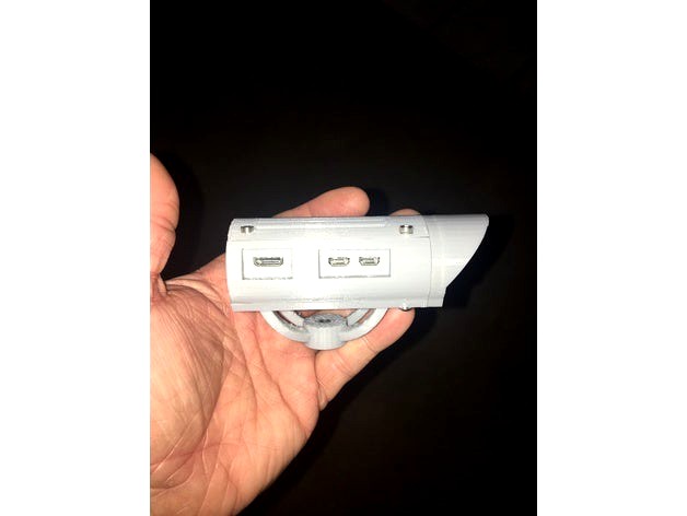
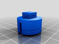
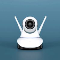
Raspberry Pi Zero W Security Camera by agilliam
by Thingiverse
Last crawled date: 3 years ago
Im not the greatest at writing up howto's! So please be patient with me!
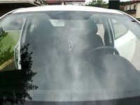
I had a problem with my girlfriends kids with lies and also hurting my daughter so I decided to make up a cheap camera. Plus it doubled as a security camera for the house when away as well.
The files will be optimized from 3yourmind with the exception of the top with vents. For some reason, the optimized slices weird in flashprint. I have not printed in ReplicatorG or Simplify3d. I have included the origional and optimized version for both.
For this project you will need
Printed parts;
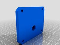
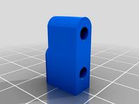
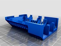
1x main body
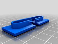
1x top vents
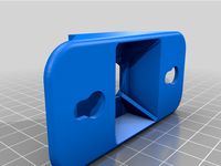
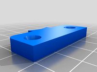
1x bottom
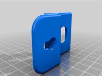
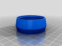
1x front bezel
Ive also included the .py scripts for RED led and GREEN led as downloads.
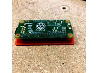
1x Raspberry Pi Zero W (need built in wifi!)https://www.adafruit.com/product/3400
1x 8GB + Micro SD Card (MAKE SURE ITS COMPATIBLE AND KNOWN TO WORK)
I use Samsung 32GB (half yellow and half black) and works GREAT.
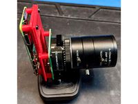
1x Raspberry Pi Cam (ebay purchased 5mp with 75 degree fisheye with night vision) (wider angle would be best!)https://www.ebay.com/itm/1080P-Camera-Module-Board-5MP-130-Fish-Eye-IR-Night-Vision-For-Raspberry-Pi/202068425949?epid=582139582&hash=item2f0c377cdd:g:Og4AAOSwR21Zzfdn
1x Raspberry Pi Zero Camera ribbon cable (shorter one it would be better 40mm - 60mm?)https://www.adafruit.com/product/3157
1x Micro tactile momentary switch (reset switch) (through hole type)https://www.ebay.com/itm/CLEARANCE-20-pcs-6-x-6-x7mm-PCB-Momentary-Tactile-Tact-Push-Button-Switch-4Pins/172516258499?_trkparms=aid%3D555019%26algo%3DPL.BANDIT%26ao%3D1%26asc%3D41451%26meid%3D217ef34e4f9e408991457486e4cf1bfa%26pid%3D100506%26rk%3D1%26rkt%3D1%26&_trksid=p2045573.c100506.m3226
1x 30mm fan 5V (important need 5V) (either 7mm or 10mm thick)https://www.ebay.com/itm/30mm-5V-Cooling-Fan-for-Raspberry-Pi-and-RepRap-3D-Printer/142351923704?epid=927595224&hash=item2124d5f9f8:g:9k8AAOSwE0JY9HPE
1x RED 3mm LED (Blinks, but would like to make it only blink when movement is detected)https://www.adafruit.com/product/777 (this is a pack of 25 but you only need 1(source maybe fries?)
1x GREEN 3mm LED (Stays lit showing power on)https://www.adafruit.com/product/779
2x 330 OHM Resistors (for LEDS)
Miscellaneous 3mm bolts and 2mm bolts.
Some wire and soldering tools.
Some small shrink tube
4x 2mm x 8-10mm long hex head bolts (pan or socket)
4x 3mm x 35mm long hex head bolts (pan or socket) (bolts top, main body & bottom)
2x 3mm x 5mm long hex head bolts (pan or socket) (holds one end of the zero down)
4x 3mm x 8-10mm long hex head bolts (pan or socket) (holds front to main body)
4x 3mm x 10 - 12mm long head head bolts (pan or socket) (holds fan to base)
4x 3mm nuts
1x Press in threaded insert. I got these from McFadden Dale Hardware. (I don't have the part number and cant find it on their website.) This will change soon to a new style.
First thing you will need to do is drill the holes through the Raspberry Pi Zero W on all 4 corners with a 3mm drill bit.
Mount the RPI Camera to the front of the main body using 2mm screws.
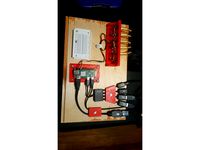
Youll need to solder 2 wires to the tactile switch, make sure you solder the wires to the correct pins. put small shrink tube to cover the wire/solder/pins of switch, and you can clip the other 2 pins off that you dont use. Make sure the wires are long enough to reach the Pi to the reset pins and solder.
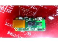
Next youll need to solder the fan to the RPI Zero W with RED wire going to pin #4 and BLACK going to pin #6. (This will make the fan run whenever the pi is plugged in)
Then you will need to solder a 330 Ohm resistor to the cathode side (negativ) leg on the LEDS, then a section of wire from the resistor out. Make sure to put shrink tube over the resistor and solder connections!!
Solder RED wire from the ANODE (Positive side) to connect to pins on the PI.
Now you can share the ground's by making a Y connection for the LEDS, I kept it simple and used a seperate ground for each LED.
For the RED LED (blinking LED) I connected the Positive (anode) side of LED to pin #13, and connected the Negative (Cathode) side of LED to pin #20.
For the GREEN LED (Always On) I connected the Positive (anode) side of LED to pin #11, and connected the Negative (Cathode) side to pin #9.
Push the LED's in the position of your liking. I put the RED on the LEFT hole looking AT the camera, and the GREEN in the RIGHT hole.
Once all soldering is done, you can now plug in the ribbon cable for the camera and mount the RPI Zero to the main body using 3mmx5mm hex head screws. These will go in the FRONT of the PI near the camera connection.
Connect the camera to the ribbon cable and screw the front onto the main body using 4x 3mmx5mm hex head bolts.
Press or thread in the threaded insert to the bottom mount..
Once that's all done use the 4 35mm bolts to bolt all 3 pieces together and use the nuts on the bottom to secure it.
Install Raspbian Jessie or whatever flavor you like on SD card, make sure you do the normal setup using;
sudo raspi-config
enable camera, set locale, set timezone, etc etc.
You will need to install mjpg_streamer;https://github.com/jacksonliam/mjpg-streamer
Once that's installed, you will need to add this into your /etc/rc.local (BEFORE exit 0)
LD_LIBRARY_PATH=/usr/local/lib mjpg_streamer -b -i "input_raspicam.so -rot 180 -br 55 -sa 20 -sh 100 -quality 100 -vs -ex night -awb auto" /tmp/stream -o "output_http.so -w /usr/local/www -c YOURUSERNAME:YOURPASSWORD"
That will start mjpg_streamer upon boot of your pi zero.
Then add these to /etc/rc.local BEFORE exit 0
python /home/pi/red_led_blink.py &
python /home/pi/green_led_on.py &
sudo iptables -t nat -A PREROUTING -p tcp --dport 80 -j REDIRECT --to-port 8080
This allows you to connect to port 80, as well as 8080.
Then for your /home/pi/red_led_blink.py file
nano /home/pi/red_led_blink.py
---- start ----
import RPi.GPIO as GPIO
import time
LedPin = 13 # pin13
def setup():
GPIO.setmode(GPIO.BOARD) # Numbers GPIOs by physical location
GPIO.setup(LedPin, GPIO.OUT) # Set LedPin's mode is output
GPIO.output(LedPin, GPIO.HIGH) # Set LedPin high(+3.3V) to turn on led
def blink():
while True:
GPIO.output(LedPin, GPIO.HIGH) # led on
time.sleep(1)
GPIO.output(LedPin, GPIO.LOW) # led off
time.sleep(5)
def destroy():
GPIO.output(LedPin, GPIO.LOW) # led off
GPIO.cleanup() # Release resource
if name == 'main': # Program start from here
setup()
try:
blink()
except KeyboardInterrupt: # When 'Ctrl+C' is pressed, the child program destroy() will be executed.
destroy()
---- end ----
CTRL o (save)
CTRL x (exit)
Then for your green_led_on.py file
nano green_led_on.py
---- start ----
import RPi.GPIO as GPIO
import time
LedPin = 11 # pin11
def setup():
GPIO.setmode(GPIO.BOARD) # Numbers GPIOs by physical location
GPIO.setup(LedPin, GPIO.OUT) # Set LedPin's mode is output
GPIO.output(LedPin, GPIO.HIGH) # Set LedPin high(+3.3V) to turn on led
def on():
while True:
GPIO.output(LedPin, GPIO.HIGH) # led on
time.sleep(1)
GPIO.output(LedPin, GPIO.LOW) # led off
time.sleep(3)
def destroy():
GPIO.output(LedPin, GPIO.LOW) # led off
GPIO.cleanup() # Release resource
if name == 'main': # Program start from here
setup()
try:
on()
except KeyboardInterrupt: # When 'Ctrl+C' is pressed, the child program des$
destroy()
---- end ----
CTRL o (save)
CTRL x (exit)
Then;
chmod 655 red_led_blink.py
chmod 655 green_led_on.py
Once that's done, reboot your pi
sudo reboot
Once it comes up your green light should be on and the red light will flash at intervals. You can change the interval in the red script file by changing sleep on and sleep off mine are sleep 1 on and sleep 5 off. So its on for 1 second, then shuts off for 5, then turns back on for 1. etc etc etc.
Then just point your web browser to your IP address of your pi Zero, in my case I can use either;
http://10.1.1.1
or http://10.1.1.1:8080 (most ISP block 80, so you can get around that by using a dyndns and portmap on your router)
These cameras will work with Ispy Surveillance and security software. I have yet to get it working with the one software I love the most.... Active Webcam.
As I said I'm not that great with write-ups and how to's. I hope to get better!
I had a problem with my girlfriends kids with lies and also hurting my daughter so I decided to make up a cheap camera. Plus it doubled as a security camera for the house when away as well.
The files will be optimized from 3yourmind with the exception of the top with vents. For some reason, the optimized slices weird in flashprint. I have not printed in ReplicatorG or Simplify3d. I have included the origional and optimized version for both.
For this project you will need
Printed parts;
1x main body
1x top vents
1x bottom
1x front bezel
Ive also included the .py scripts for RED led and GREEN led as downloads.
1x Raspberry Pi Zero W (need built in wifi!)https://www.adafruit.com/product/3400
1x 8GB + Micro SD Card (MAKE SURE ITS COMPATIBLE AND KNOWN TO WORK)
I use Samsung 32GB (half yellow and half black) and works GREAT.
1x Raspberry Pi Cam (ebay purchased 5mp with 75 degree fisheye with night vision) (wider angle would be best!)https://www.ebay.com/itm/1080P-Camera-Module-Board-5MP-130-Fish-Eye-IR-Night-Vision-For-Raspberry-Pi/202068425949?epid=582139582&hash=item2f0c377cdd:g:Og4AAOSwR21Zzfdn
1x Raspberry Pi Zero Camera ribbon cable (shorter one it would be better 40mm - 60mm?)https://www.adafruit.com/product/3157
1x Micro tactile momentary switch (reset switch) (through hole type)https://www.ebay.com/itm/CLEARANCE-20-pcs-6-x-6-x7mm-PCB-Momentary-Tactile-Tact-Push-Button-Switch-4Pins/172516258499?_trkparms=aid%3D555019%26algo%3DPL.BANDIT%26ao%3D1%26asc%3D41451%26meid%3D217ef34e4f9e408991457486e4cf1bfa%26pid%3D100506%26rk%3D1%26rkt%3D1%26&_trksid=p2045573.c100506.m3226
1x 30mm fan 5V (important need 5V) (either 7mm or 10mm thick)https://www.ebay.com/itm/30mm-5V-Cooling-Fan-for-Raspberry-Pi-and-RepRap-3D-Printer/142351923704?epid=927595224&hash=item2124d5f9f8:g:9k8AAOSwE0JY9HPE
1x RED 3mm LED (Blinks, but would like to make it only blink when movement is detected)https://www.adafruit.com/product/777 (this is a pack of 25 but you only need 1(source maybe fries?)
1x GREEN 3mm LED (Stays lit showing power on)https://www.adafruit.com/product/779
2x 330 OHM Resistors (for LEDS)
Miscellaneous 3mm bolts and 2mm bolts.
Some wire and soldering tools.
Some small shrink tube
4x 2mm x 8-10mm long hex head bolts (pan or socket)
4x 3mm x 35mm long hex head bolts (pan or socket) (bolts top, main body & bottom)
2x 3mm x 5mm long hex head bolts (pan or socket) (holds one end of the zero down)
4x 3mm x 8-10mm long hex head bolts (pan or socket) (holds front to main body)
4x 3mm x 10 - 12mm long head head bolts (pan or socket) (holds fan to base)
4x 3mm nuts
1x Press in threaded insert. I got these from McFadden Dale Hardware. (I don't have the part number and cant find it on their website.) This will change soon to a new style.
First thing you will need to do is drill the holes through the Raspberry Pi Zero W on all 4 corners with a 3mm drill bit.
Mount the RPI Camera to the front of the main body using 2mm screws.
Youll need to solder 2 wires to the tactile switch, make sure you solder the wires to the correct pins. put small shrink tube to cover the wire/solder/pins of switch, and you can clip the other 2 pins off that you dont use. Make sure the wires are long enough to reach the Pi to the reset pins and solder.
Next youll need to solder the fan to the RPI Zero W with RED wire going to pin #4 and BLACK going to pin #6. (This will make the fan run whenever the pi is plugged in)
Then you will need to solder a 330 Ohm resistor to the cathode side (negativ) leg on the LEDS, then a section of wire from the resistor out. Make sure to put shrink tube over the resistor and solder connections!!
Solder RED wire from the ANODE (Positive side) to connect to pins on the PI.
Now you can share the ground's by making a Y connection for the LEDS, I kept it simple and used a seperate ground for each LED.
For the RED LED (blinking LED) I connected the Positive (anode) side of LED to pin #13, and connected the Negative (Cathode) side of LED to pin #20.
For the GREEN LED (Always On) I connected the Positive (anode) side of LED to pin #11, and connected the Negative (Cathode) side to pin #9.
Push the LED's in the position of your liking. I put the RED on the LEFT hole looking AT the camera, and the GREEN in the RIGHT hole.
Once all soldering is done, you can now plug in the ribbon cable for the camera and mount the RPI Zero to the main body using 3mmx5mm hex head screws. These will go in the FRONT of the PI near the camera connection.
Connect the camera to the ribbon cable and screw the front onto the main body using 4x 3mmx5mm hex head bolts.
Press or thread in the threaded insert to the bottom mount..
Once that's all done use the 4 35mm bolts to bolt all 3 pieces together and use the nuts on the bottom to secure it.
Install Raspbian Jessie or whatever flavor you like on SD card, make sure you do the normal setup using;
sudo raspi-config
enable camera, set locale, set timezone, etc etc.
You will need to install mjpg_streamer;https://github.com/jacksonliam/mjpg-streamer
Once that's installed, you will need to add this into your /etc/rc.local (BEFORE exit 0)
LD_LIBRARY_PATH=/usr/local/lib mjpg_streamer -b -i "input_raspicam.so -rot 180 -br 55 -sa 20 -sh 100 -quality 100 -vs -ex night -awb auto" /tmp/stream -o "output_http.so -w /usr/local/www -c YOURUSERNAME:YOURPASSWORD"
That will start mjpg_streamer upon boot of your pi zero.
Then add these to /etc/rc.local BEFORE exit 0
python /home/pi/red_led_blink.py &
python /home/pi/green_led_on.py &
sudo iptables -t nat -A PREROUTING -p tcp --dport 80 -j REDIRECT --to-port 8080
This allows you to connect to port 80, as well as 8080.
Then for your /home/pi/red_led_blink.py file
nano /home/pi/red_led_blink.py
---- start ----
import RPi.GPIO as GPIO
import time
LedPin = 13 # pin13
def setup():
GPIO.setmode(GPIO.BOARD) # Numbers GPIOs by physical location
GPIO.setup(LedPin, GPIO.OUT) # Set LedPin's mode is output
GPIO.output(LedPin, GPIO.HIGH) # Set LedPin high(+3.3V) to turn on led
def blink():
while True:
GPIO.output(LedPin, GPIO.HIGH) # led on
time.sleep(1)
GPIO.output(LedPin, GPIO.LOW) # led off
time.sleep(5)
def destroy():
GPIO.output(LedPin, GPIO.LOW) # led off
GPIO.cleanup() # Release resource
if name == 'main': # Program start from here
setup()
try:
blink()
except KeyboardInterrupt: # When 'Ctrl+C' is pressed, the child program destroy() will be executed.
destroy()
---- end ----
CTRL o (save)
CTRL x (exit)
Then for your green_led_on.py file
nano green_led_on.py
---- start ----
import RPi.GPIO as GPIO
import time
LedPin = 11 # pin11
def setup():
GPIO.setmode(GPIO.BOARD) # Numbers GPIOs by physical location
GPIO.setup(LedPin, GPIO.OUT) # Set LedPin's mode is output
GPIO.output(LedPin, GPIO.HIGH) # Set LedPin high(+3.3V) to turn on led
def on():
while True:
GPIO.output(LedPin, GPIO.HIGH) # led on
time.sleep(1)
GPIO.output(LedPin, GPIO.LOW) # led off
time.sleep(3)
def destroy():
GPIO.output(LedPin, GPIO.LOW) # led off
GPIO.cleanup() # Release resource
if name == 'main': # Program start from here
setup()
try:
on()
except KeyboardInterrupt: # When 'Ctrl+C' is pressed, the child program des$
destroy()
---- end ----
CTRL o (save)
CTRL x (exit)
Then;
chmod 655 red_led_blink.py
chmod 655 green_led_on.py
Once that's done, reboot your pi
sudo reboot
Once it comes up your green light should be on and the red light will flash at intervals. You can change the interval in the red script file by changing sleep on and sleep off mine are sleep 1 on and sleep 5 off. So its on for 1 second, then shuts off for 5, then turns back on for 1. etc etc etc.
Then just point your web browser to your IP address of your pi Zero, in my case I can use either;
http://10.1.1.1
or http://10.1.1.1:8080 (most ISP block 80, so you can get around that by using a dyndns and portmap on your router)
These cameras will work with Ispy Surveillance and security software. I have yet to get it working with the one software I love the most.... Active Webcam.
As I said I'm not that great with write-ups and how to's. I hope to get better!
Similar models
thingiverse
free
Raspberry Pi Zero Soldering Holder by PacketPaul
...our pi exactly 8.2 mm above the bottom plate. the pins rest securely in a small box assuring the correct alignment with the pi.
thingiverse
free
Raspberry Pi Zero GPIO Pin Solder Jig
...ero gpio pin solder jig
thingiverse
i use this to hold the rpi zero on the bench when prototyping as well as soldering the pins.
thingiverse
free
RPI Raspberry Pi Zero WH case with camera by RobotLovingGuy
...era cable
1x 30mm suction cup (https://www.amazon.com/gp/product/b073s5tx8w/ref=ppx_yo_dt_b_asin_title_o00_s00?ie=utf8&psc=1)
thingiverse
free

Raspberry PI Zero Camera Case (v. 1.0.0)
...nnector cable 38mm long
5 mb camera module
1/4 inch 6mm high hex nut (for tripod or camera holder mount)
4x m2*5 flat head screws
thingiverse
free
raspberry pi LCD 1/4 Camera Adapter by UEPONYA
...raspberry pi lcd 1/4 camera adapter by ueponya
thingiverse
1x 1/4 nut
4x m3x10 bolt
4x m3 nut
thingiverse
free
raspberry pi zero hq camera bracket by openloopengineer
...i with the same size screws.
i used the short raspberry pi zero camera cable that comes with the official raspberry pi zero case.
grabcad
free

Arducam Multi Camera Module V2 for Raspberry Pi Zero
...cad
this multi-camera adapter board is designed for raspberry pi zero and lets you connect two 5mp, 8mp,12mp cameras to pi zero.
thingiverse
free
RPI Zero CCTV case by RobotLovingGuy
... is 30mm)
2x 30mm suction cup (https://www.amazon.com/gp/product/b073s5tx8w/ref=ppx_yo_dt_b_asin_title_o00_s00?ie=utf8&psc=1)
thingiverse
free
Raspberry Pi Zero Camera Holder by robohead456
.... if you want to use m3 bolts you will need to use a drill bit to make the mounting holes in the pi and the printed parts larger.
thingiverse
free
ActionPi Case by andreacioni
...o hear from you!
actionpi case is totally inspired from an already existing project raspberry pi zero wifi camera by dimwit-dave.
Agilliam
thingiverse
free
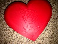
Heart Box by agilliam
...ut, my daughter saw it and wanted one, so i used the same design but put a my little pony on it. see my other "things".
thingiverse
free
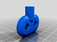
Clock Winding Key by agilliam
...t this way.
if you need one with larger holes for different sized clocks, let me know ill be more than happy to accommodate them!
thingiverse
free

FFCP 2016 Build Plate Harness Plug by agilliam
...el where they made the hole smaller.
this prevents junk from falling underneath and causing overheating and clogging fans.
enjoy!
thingiverse
free
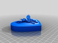
Heart shaped box with My Little Pony by agilliam
...t. i got the mlp image from sketchup and cocked it at an slight angle and slices it. placed it ontop of the lid giving a 3d look.
thingiverse
free
Traxxas Nitro Hawk Parts by agilliam
...cided to make servo mounts, etc. i hope to try to make everything plastic, and put on here even gear box... a personal challenge.
thingiverse
free

FFCP FlashForge Creator Pro Filament Guide by agilliam
...the tube, i don't care for the black stuff flashforge gives you)
no support nor raft needed, very easy and straight forward.
thingiverse
free
FlashForge Build Plate Harness Plug by agilliam
...tuff dropping inside!
you may need to file just a bit if your printer isn't calibrated highly like this one. its a tight fit!
thingiverse
free
FlashForge Creator Pro Wire Plug/Retainer by agilliam
...o the wire cavity to help hold the wires into place.
still learning sketchup! i'm used to autocad, but this is way different!
thingiverse
free
Croquet Malet Pad by agilliam
...s a no brand name croquet set, i think they are standard though from what i can remember when i was a child and played with them.
thingiverse
free
DashCam T slot adapter to Garmin by agilliam
...ints fine it nylon, abs, and pla. with nylon and abs you will need rafts as there is a very small surface for contact on the rim.
Zero
3ddd
$1

ZERO, BEAM
...zero, beam
3ddd
zero
поворотная люстра zero , beam
design_connected
$9

Zero-in
...zero-in
designconnected
established & sons zero-in tables computer generated 3d model. designed by jay osgerby .
3ddd
free
Sub-Zero
...sub-zero
3ddd
sub-zero , голова
sub-zero corona render!
3ddd
$1
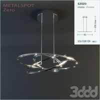
Metalspot / Zero
...metalspot / zero
3ddd
metalspot
metalspot zero
3ddd
$1

Catalano Zero
...catalano zero
3ddd
catalano , унитаз
catalano zero
3ddd
$1

SUB ZERO
... sub zero
the first and only 3d model of sub zero refrigerator.
the model is very accurate.
turbosquid
free

Zero
... available on turbo squid, the world's leading provider of digital 3d models for visualization, films, television, and games.
turbosquid
free

Zero
... available on turbo squid, the world's leading provider of digital 3d models for visualization, films, television, and games.
turbosquid
free

Zero
... available on turbo squid, the world's leading provider of digital 3d models for visualization, films, television, and games.
3ddd
$1

ZERO / Hide
...zero / hide
3ddd
zero
polys: 25486
wire-spline
Raspberry
3d_export
free

raspberry
...raspberry
3dexport
3d model of a raspberry. i tried to make it realistic.
turbosquid
$27
Raspberries
...y free 3d model raspberries for download as max, obj, and stl on turbosquid: 3d models for games, architecture, videos. (1354176)
turbosquid
$14

Raspberries
...y free 3d model raspberries for download as max, obj, and fbx on turbosquid: 3d models for games, architecture, videos. (1364663)
3d_export
$5
raspberry pi
...raspberry pi
3dexport
carcasa para la raspberry pi
turbosquid
$99
Raspberry
... available on turbo squid, the world's leading provider of digital 3d models for visualization, films, television, and games.
turbosquid
$10

raspberries
... available on turbo squid, the world's leading provider of digital 3d models for visualization, films, television, and games.
archive3d
free

Raspberries 3D Model
...raspberries 3d model archive3d raspberries raspberry raspberries n300911 - 3d model (*.3ds) for interior 3d...
3d_export
$5

raspberry fruit
...raspberry fruit
3dexport
3d_export
$5

raspberry
...y different sizes. their color ranges from light burgundy to pink. there are formats: obj, 3ds, blend, dae, fbx, mtl.<br>:)
evermotion
$12

raspberries 23 am130
...evermotion raspberries 23 am130 evermotion key 23 food fruit raspberry fruits am130 raspberries highly detailed 3d model of raspberries...
Pi
design_connected
$11

Pi
...pi
designconnected
ligne roset pi chairs computer generated 3d model. designed by thibault desombre.
3d_export
$5
raspberry pi
...raspberry pi
3dexport
carcasa para la raspberry pi
turbosquid
$18
pied
... available on turbo squid, the world's leading provider of digital 3d models for visualization, films, television, and games.
3ddd
$1
Emme pi light
...emme pi light
3ddd
emme pi light
люста emme pi light
3ddd
$1
Emme pi light
...emme pi light
3ddd
emme pi light
бра классическое emme pi light
3ddd
$1

Emme Pi Light
...emme pi light
3ddd
emme pi light
3ddd
$1

Emme Pi Light
...emme pi light
3ddd
emme pi light
design_connected
$16
Pi-Air
...pi-air
designconnected
living divani pi-air lounge chairs computer generated 3d model. designed by harry & camila.
3d_ocean
$15

Manneken Pis
...picting a naked little boy urinating into a fountain’s basin. (wikipedia) the model was sculpted in blender 2.70a rendered wit...
3ddd
$1

Emme pi light
...emme pi light
3ddd
emme pi light
люстра классическая фирма: emme pi light
артикул: 3595/5/cot/12/wh
Security
3d_export
$40
security cam
...security cam
3dexport
home security camera
turbosquid
$55
Secure robot
...squid
royalty free 3d model secure robot for download as obj on turbosquid: 3d models for games, architecture, videos. (1516503)
turbosquid
$14

Security camera.
...d
royalty free 3d model security camera. for download as fbx on turbosquid: 3d models for games, architecture, videos. (1192695)
turbosquid
$5
Security Camera
...id
royalty free 3d model security camera for download as fbx on turbosquid: 3d models for games, architecture, videos. (1260457)
turbosquid
$5
Security Post
...quid
royalty free 3d model security post for download as fbx on turbosquid: 3d models for games, architecture, videos. (1274835)
turbosquid
$4

Security Camera
...id
royalty free 3d model security camera for download as fbx on turbosquid: 3d models for games, architecture, videos. (1298323)
turbosquid
$19
Security cam
...oyalty free 3d model security cam for download as ige and obj on turbosquid: 3d models for games, architecture, videos. (1331128)
turbosquid
$5

security hole
...yalty free 3d model security hole for download as 3dm and max on turbosquid: 3d models for games, architecture, videos. (1669645)
turbosquid
$95

Megalopolis security
... model megalopolis security for download as max, obj, and fbx on turbosquid: 3d models for games, architecture, videos. (1253177)
turbosquid
$40
Security Cam
...y free 3d model security cam for download as ma, fbx, and obj on turbosquid: 3d models for games, architecture, videos. (1601103)
Camera
archibase_planet
free
Camera
...base planet
camera surveillance camera video camera
camera surveillance n090211 - 3d model (*.3ds) for interior 3d visualization.
archibase_planet
free
Camera
...hibase planet
camera security camera video camera
camera security n210515 - 3d model (*.gsm+*.3ds) for exterior 3d visualization.
archibase_planet
free
Camera
...se planet
camera web camera webcam
camera butterfly usb pc camera n090713 - 3d model (*.gsm+*.3ds) for interior 3d visualization.
archibase_planet
free
Camera
...mera
archibase planet
surveillance camera video camera camcorder
camera n011211 - 3d model (*.3ds) for exterior 3d visualization.
archibase_planet
free
Camera
...camera
archibase planet
camera digital camera
camera canon digital n041211 - 3d model (*.3ds) for interior 3d visualization.
archibase_planet
free

Camera
...camera
archibase planet
camera film camera phototechnique
camera n100214 - 3d model (*.gsm+*.3ds) for interior 3d visualization.
archibase_planet
free
Camera
...amera
archibase planet
camera video camera camcorder
camera video n070315 - 3d model (*.gsm+*.3ds) for interior 3d visualization.
archibase_planet
free

Camera
...rchibase planet
camera video camera camcorder
camera studio n101213 - 3d model (*.gsm+*.3ds+*.max) for interior 3d visualization.
archibase_planet
free
Camera
...ibase planet
digital camera camera phototechnique
camera canon ixus 400 n310311 - 3d model (*.3ds) for interior 3d visualization.
archibase_planet
free
Camera
...ase planet
photocamera video camera camera
camera sony t300 black n291010 - 3d model (*.gsm+*.3ds) for interior 3d visualization.
W
3ddd
$1
chair W
...chair w
3ddd
chair w
3ddd
$1

кресло w
...кресло w
3ddd
капитоне
кресло w
3ddd
$1
KUTEK (W) W-ZW-5
...kutek (w) w-zw-5
3ddd
kutek
3d модель люстри (w) w-zw-5 фабрики kutek. в архиве: max2012, obj, fbx, mat.(два варианта металла)
3ddd
$1
KUTEK (W) W-ZW-3
...kutek (w) w-zw-3
3ddd
kutek
3d модель люстри (w) w-zw-3 фабрики kutek. в архиве: max2012, obj, fbx, mat. (два варианта металла)
3ddd
$1
KUTEK (W) W-ZW-1
...kutek (w) w-zw-1
3ddd
kutek
3d модель люстри (w) w-zw-1 фабрики kutek. в архиве: max2012, obj, fbx, mat (два варианта металла).
3ddd
free
aneken W&W
...aneken w&w
3ddd
2 женских манекена, ценники и фолио. материалы и текстуры прилагаются.
design_connected
$9
KTribe W
...ktribe w
designconnected
ktribe w computer generated 3d model. designed by starck, philippe.
design_connected
$16

Troy W
...troy w
designconnected
magis troy w computer generated 3d model. designed by wanders, marcel.
turbosquid
$9
Menu - Benjamin Hubert - W W Carafe
... available on turbo squid, the world's leading provider of digital 3d models for visualization, films, television, and games.
turbosquid
$9

Menu - Benjamin Hubert - W W Carafe
... available on turbo squid, the world's leading provider of digital 3d models for visualization, films, television, and games.