Thingiverse
Raspberry Pi Arcade Cabinet
by Thingiverse
Last crawled date: 4 years, 3 months ago
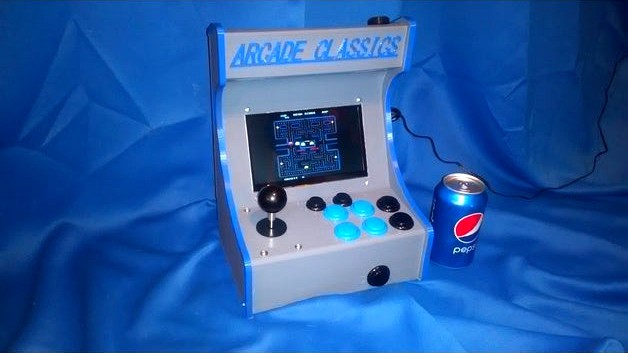
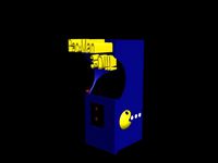
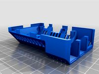
This is an arcade cabinet designed for a raspberry pi using a 7inch HDMI LCD display and a small amplifier with micro speaker for sound. I have made several of these and it works great.
Parts i used not including the Pi can be found here -
Arcade stick and buttons - https://www.amazon.com/gp/product/B0788MJJX1/ref=ppx_yo_dt_b_asin_title_o09_s00?ie=UTF8&psc=1
Amp with potentiometer - https://www.amazon.com/gp/product/B07GL3NCLV/ref=ppx_yo_dt_b_asin_title_o02_s00?ie=UTF8&psc=1
Audio jack plug - https://www.amazon.com/gp/product/B077XNTSF9/ref=ppx_yo_dt_b_asin_title_o02_s00?ie=UTF8&psc=1
Mini speaker - https://www.amazon.com/gp/product/B07FTB281F/ref=ppx_yo_dt_b_asin_title_o02_s00?ie=UTF8&psc=1
7 inch LCD - https://www.amazon.com/gp/product/B07N1P5YWR/ref=ppx_yo_dt_b_asin_title_o00_s00?ie=UTF8&psc=1
The single model is 240mm wide x 173mm long x 312 tall.
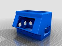
The split model is split in half in the Z direction for shorter printers.
Also the split model does not have the hole in the top for the amplifier volume pot to mount. You can drill a hole if you want to use the amp i listed.
I used an Anet A8 plus printer for the single model. I printed with Slic3r using 25% infill , .25 layer heights with 0.4 nozzle. Removable supports are made into the models so no need to use slicing supports. Also i did use variable layer heights where the joystick and buttons are and near the top to help with the overhangs and give a better finish.
Takes about 36 hours to print the single print model if i remember correct.
To assemble use #6 x 3/4" long wood screws to hold the lower plate, #6 x 1/2" long bolts and nuts for the joystick and LCD, and #4 x 1/4" long wood screws for mounting the side moulds, Pi and USB control board. If using the split models use #6 x 3/8" long wood screws to connect the top and bottom. The amplifier and speaker both mount to the amp mount. The volume pot sticks out through the hole in the top and the pots nut can be used to clamp it in place. I wired an audio jack to the amplifier. Connect right or left channel from the jack to the amp signal input, connect the ground from the jack to the negative voltage amp input, connect the amp voltage input + to one of the Pi's + output pins. Amp outputs to the speaker.
Print, assemble, have fun.
I have included and IGES file for anyone who wants to modify the cabinet.
Parts i used not including the Pi can be found here -
Arcade stick and buttons - https://www.amazon.com/gp/product/B0788MJJX1/ref=ppx_yo_dt_b_asin_title_o09_s00?ie=UTF8&psc=1
Amp with potentiometer - https://www.amazon.com/gp/product/B07GL3NCLV/ref=ppx_yo_dt_b_asin_title_o02_s00?ie=UTF8&psc=1
Audio jack plug - https://www.amazon.com/gp/product/B077XNTSF9/ref=ppx_yo_dt_b_asin_title_o02_s00?ie=UTF8&psc=1
Mini speaker - https://www.amazon.com/gp/product/B07FTB281F/ref=ppx_yo_dt_b_asin_title_o02_s00?ie=UTF8&psc=1
7 inch LCD - https://www.amazon.com/gp/product/B07N1P5YWR/ref=ppx_yo_dt_b_asin_title_o00_s00?ie=UTF8&psc=1
The single model is 240mm wide x 173mm long x 312 tall.
The split model is split in half in the Z direction for shorter printers.
Also the split model does not have the hole in the top for the amplifier volume pot to mount. You can drill a hole if you want to use the amp i listed.
I used an Anet A8 plus printer for the single model. I printed with Slic3r using 25% infill , .25 layer heights with 0.4 nozzle. Removable supports are made into the models so no need to use slicing supports. Also i did use variable layer heights where the joystick and buttons are and near the top to help with the overhangs and give a better finish.
Takes about 36 hours to print the single print model if i remember correct.
To assemble use #6 x 3/4" long wood screws to hold the lower plate, #6 x 1/2" long bolts and nuts for the joystick and LCD, and #4 x 1/4" long wood screws for mounting the side moulds, Pi and USB control board. If using the split models use #6 x 3/8" long wood screws to connect the top and bottom. The amplifier and speaker both mount to the amp mount. The volume pot sticks out through the hole in the top and the pots nut can be used to clamp it in place. I wired an audio jack to the amplifier. Connect right or left channel from the jack to the amp signal input, connect the ground from the jack to the negative voltage amp input, connect the amp voltage input + to one of the Pi's + output pins. Amp outputs to the speaker.
Print, assemble, have fun.
I have included and IGES file for anyone who wants to modify the cabinet.
Similar models
thingiverse
free

Audio Amplifier Cover
...or drok audio amplifier tda7377
https://www.amazon.com/gp/product/b07k6gbv7r/ref=ppx_yo_dt_b_asin_title_o02_s00?ie=utf8&psc=1
thingiverse
free
50A Power Supply Cover W/LCD Display by hkgary_g
...lpage_o06_s01?ie=utf8&psc=1
power socket
www.amazon.com/gp/product/b06xnmt3wl/ref=oh_aui_detailpage_o06_s00?ie=utf8&psc=1
thingiverse
free

NAS Raspberry Pi 4 by Romaricovert
..._title_o02_s00?ie=utf8&psc=1
https://www.amazon.fr/gp/product/b01lxrwwb6/ref=ppx_yo_dt_b_asin_title_o02_s01?ie=utf8&psc=1
thingiverse
free

U360gts, small frame
...ectronics&sr=1-1-catcorr
more information about the project:
https://github.com/raul-ortega/u360gts/blob/master/wiki/index.md
thingiverse
free

3018 CNC Upgraded Z Axis mount for 500W spindle
...xtf/ref=ppx_yo_dt_b_asin_title_o01_s00?ie=utf8&psc=1&fbclid=iwar3uik1j5s29do_htrjlg-sekqdojiig08_sdml7pj2twokrx2n75f5nj4g
thingiverse
free
Raspberry Pi Retrogaming Case by Eguin
...for use in future projects, and if you have similar things already can be used in their place. in...
thingiverse
free

Enceinte bluetooth
...s://www.amazon.fr/gp/product/b07jqmf3kk/ref=ppx_yo_dt_b_asin_title_o02_s00?ie=utf8&psc=1
use a 18650 battery for alimentation
grabcad
free

BMG Alu Mount
...bcad
bmg/titan nema 17 mount.
https://www.amazon.com/gp/product/b07syyg118/ref=ppx_yo_dt_b_asin_title_o02_s00?ie=utf8&psc=1
thingiverse
free

Guitar Pickup Winder
...=utf8&psc=1
speed adjustmenthttps://www.amazon.com/gp/product/b07vpnhs5j/ref=ppx_yo_dt_b_asin_title_o02_s01?ie=utf8&psc=1
thingiverse
free

Raspberry 4B Nextcloud
...00? ie = utf8 & psc = 1
ssd: https://www.amazon.de/gp/product/b07hncwcnl/ref=ppx_yo_dt_b_asin_title_o02_s00?ie=utf8&psc=1
Arcade
3ddd
$1
Simas / Arcade
...dd
simas , simas arcade , тумба
simas arcade 46
3d_export
$5

Arcade
...arcade
3dexport
3ddd
free
Turri / Arcade
...turri / arcade
3ddd
turri , журнальный
turri / arcade
turbosquid
$35

arcade
... available on turbo squid, the world's leading provider of digital 3d models for visualization, films, television, and games.
turbosquid
$15
Arcade
... available on turbo squid, the world's leading provider of digital 3d models for visualization, films, television, and games.
turbosquid
free
Arcade
... available on turbo squid, the world's leading provider of digital 3d models for visualization, films, television, and games.
3d_ocean
$16

Arcade Game
...tomate button coin computer console fun game gamer gaming joystick machine play side art video game
detailed arcade game machine.
3d_export
$5

Arcade 3D Model
...arcade 3d model
3dexport
architecture arcade elements decor
arcade 3d model evgenadm 86783 3dexport
3d_export
$10

Arcade 3D Model
...arcade 3d model
3dexport
arcade arch porch portico well round
arcade 3d model loscarpello 54648 3dexport
3d_export
$9
Arcade 3D Model
...arcade 3d model
3dexport
arcade architecture old building classic arch
arcade 3d model lotfy 150 3dexport
Raspberry
3d_export
free

raspberry
...raspberry
3dexport
3d model of a raspberry. i tried to make it realistic.
turbosquid
$27
Raspberries
...y free 3d model raspberries for download as max, obj, and stl on turbosquid: 3d models for games, architecture, videos. (1354176)
turbosquid
$14

Raspberries
...y free 3d model raspberries for download as max, obj, and fbx on turbosquid: 3d models for games, architecture, videos. (1364663)
3d_export
$5
raspberry pi
...raspberry pi
3dexport
carcasa para la raspberry pi
turbosquid
$99

Raspberry
... available on turbo squid, the world's leading provider of digital 3d models for visualization, films, television, and games.
turbosquid
$10

raspberries
... available on turbo squid, the world's leading provider of digital 3d models for visualization, films, television, and games.
archive3d
free

Raspberries 3D Model
...raspberries 3d model archive3d raspberries raspberry raspberries n300911 - 3d model (*.3ds) for interior 3d...
3d_export
$5

raspberry fruit
...raspberry fruit
3dexport
3d_export
$5

raspberry
...y different sizes. their color ranges from light burgundy to pink. there are formats: obj, 3ds, blend, dae, fbx, mtl.<br>:)
evermotion
$12

raspberries 23 am130
...evermotion raspberries 23 am130 evermotion key 23 food fruit raspberry fruits am130 raspberries highly detailed 3d model of raspberries...
Pi
design_connected
$11
Pi
...pi
designconnected
ligne roset pi chairs computer generated 3d model. designed by thibault desombre.
3d_export
$5
raspberry pi
...raspberry pi
3dexport
carcasa para la raspberry pi
turbosquid
$18
pied
... available on turbo squid, the world's leading provider of digital 3d models for visualization, films, television, and games.
3ddd
$1
Emme pi light
...emme pi light
3ddd
emme pi light
люста emme pi light
3ddd
$1
Emme pi light
...emme pi light
3ddd
emme pi light
бра классическое emme pi light
3ddd
$1
Emme Pi Light
...emme pi light
3ddd
emme pi light
3ddd
$1
Emme Pi Light
...emme pi light
3ddd
emme pi light
design_connected
$16
Pi-Air
...pi-air
designconnected
living divani pi-air lounge chairs computer generated 3d model. designed by harry & camila.
3d_ocean
$15
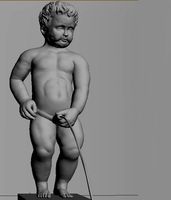
Manneken Pis
...picting a naked little boy urinating into a fountain’s basin. (wikipedia) the model was sculpted in blender 2.70a rendered wit...
3ddd
$1
Emme pi light
...emme pi light
3ddd
emme pi light
люстра классическая фирма: emme pi light
артикул: 3595/5/cot/12/wh
Cabinet
3d_ocean
$5

Cabinet
...cabinet
3docean
cabinet furniture
a lowpoly cabinet .
3d_ocean
$5

Cabinet
...cabinet
3docean
cabinet furniture
a lowpoly cabinet.
3d_ocean
$5

Cabinet
...cabinet
3docean
cabinet furniture
a lowpoly cabinet .
3d_ocean
$6

Cabinet
...cabinet
3docean
cabinet furniture
a high quality cabinet .
3d_ocean
$5

Cabinet
...cabinet
3docean
cabinet furniture
a high quality cabinet .
3d_ocean
$5

Cabinet
...cabinet
3docean
cabinet furniture
a high quality cabinet ready to use .
3ddd
free

cabinet
...cabinet
3ddd
cabinet
3d_ocean
$12

Cabinet
...cabinet
3docean
cabinet furniture
a high quality cabinet with high quality textures.
3ddd
$1

cabinet
...cabinet
3ddd
тумба
cabinet
3ddd
$1

The cabinet
...the cabinet
3ddd
тумба
the cabinet