Thingiverse

Quicko KSGER Hakko T12 Clone Soldering Station by LCSteve
by Thingiverse
Last crawled date: 2 years, 11 months ago
I decided to remix my own design and make it cleaner and more convenient for me by integrating a battery adapter to use the DeWalt 20V ecosystem since I have a bunch of them. This way I've got portability when I need it. One of the things I wanted to do was to move to a more simple 2(3) part setup to make it look cleaner and easier to print. I made the overall box into 2 parts, the front/back/top and right side are all now one piece and are meant to be printed turned 90 on the side with the open left side facing up. The other piece houses the bottom and left side and join securely to the other half with 4 screws (3mm x 10mm countersunk). This design uses the same 120V to 24V DC converter inside and C14 power connection.
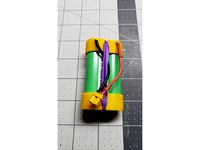
The DeWalt adapter on top was remixed from https://www.thingiverse.com/thing:2723049 which for some reason it won't let me add to the listing yet but I'll keep trying. If you only wanted to power the soldering iron with the DeWalt battery there is no reason why it also would not work just like that. Now if you decide to make one like this and use both the mains and battery setup you have two options and these are important at least one method is followed. Depending on how you setup the wiring there is a definite worry the battery will backfeed the convertor and most of them especially the cheap Chinese ones like mine don't like that one bit and will let out the magic smoke they need to run.
1st, how I did it. The power going into the soldering iron is split prior to entering and is fed by 2 separate sources. Between those 2 sources I have 5401 Schottky diodes preventing each of the units backfeeding each other. With most any diode there is give and trade in the form of forward voltage drop and heat. The heat here isn't concerning due to the draw the solder controller draws but it loses about 1.5V. They also share a ground at the controller.
2nd, the toggle on the back of the unit I used is to control the mains line coming in to the convertor it effectively shuts off power to the unit. Its a simple SPST on off switch. You can replace this with a SPDT on/off/on rocket. Without adding attritional switches would have the convertor powered anytime the mains are plugged in. The power output from the convertor would wire into one leg of the SPDT switch and the power output from the battery would connect to the other switched leg of the switch and the center would go to the power wire on the controller. This essentially becomes a make/break/make toggle connection preventing the sources from back feeding each other.
I wanted put this up available to others as it is since it's in service for me now and works but I have plans I'll be working on shortly trying to incorporate some versatility. Additions such as a holder for the iron and spool holder for examples. So keep an eye if that's of interest to you.
Parts or similar parts used:
AC/DC Convertor: https://www.amazon.com/gp/product/B06XNK1LQ3/
Solder station: https://www.aliexpress.com/item/4000239660564.html?spm=a2g0s.12269583.0.0.76ae497ejefUaj
IEC320 C14 Plugs: https://www.amazon.com/B06XV831F3/
Diodes: https://www.amazon.com/gp/product/B083J1QQHR/
Toggle Switch: https://www.amazon.com/B01M2Z70IC/
Similar models
grabcad
free

T12 Digital Controller Soldering Station For 20V Max Batteries
...freecad, and made an attempt to style the case similar to other dewalt devices. versions with and without iron...
thingiverse
free

Dewalt Battery Adapter by urw
...crews and should friction fit against 14 gauge siliconized wire.
the original cad is linked below, feel free to modify as needed.
grabcad
free

Rocker Switch
...circuit or a converter.
how to use:
use it with the power source to ensure that you can manually control when the power is on.
thingiverse
free

Duplicator i3 v2.1 Back Plate for 80mm fan by swholmstead
...res attach red to red and black to black. yellow wire on fan connector is not used.
timelapse video: https://youtu.be/v0kj_zecbne
thingiverse
free

Dewalt Battery Adapter for TS100 Soldering Iron by BlaydeRunner
... since there is no built-in battery protection with dewalt batteries, there is a risk of draining your battery below safe levels.
thingiverse
free
18650 holder 1S / 2S
...make sure they are correctly oriented. 1s instructions follow similar steps as described in the2s construction, however: solder two...
thingiverse
free

Throwie by Roothenoob
...on they positive side of the battery and the anode rested on the negative side of the battery.
i used tinkercad to make the stl.
thingiverse
free

Stun Stick by Shaputer
... i haven't gotten to that point yet.
great protection on trails where stray dogs may be encountered. cheap and easy to make.
thingiverse
free

Portable Soldering Station for TS100 by CrazyJaw
...p;psc=1
dewalt battery adapter: https://www.amazon.com/gp/product/b081t1zlbr/ref=ppx_yo_dt_b_asin_title_o05_s01?ie=utf8&psc=1
thingiverse
free

4x 18650 Charging Station w/ 5v1a Single Cell Lipo Chargers by memisis
...e button while the until is powered gives you a powered voltage from the charger.
hope you enjoy! this was a fun project for me.
Quicko
thingiverse
free

Holder Quicko T12-942 by Star_Rider
...holder quicko t12-942 by star_rider
thingiverse
petg
v2 - added cable fixing bracket
thingiverse
free

Quicko Mini STC T12 Panel by collingall
... changes.
you will also need to download the fix.stl file from the original project, and the prism mount if you want to use that.
thingiverse
free

Quicko T12 Case with DeWalt XR-LiIon battery power by Green_and_Fat
...t=searchweb0_0,searchweb201602_,searchweb201603_
20ctq045 dual shottky diode to separate power sources and avoid reverse polarity
thingiverse
free

T12 solder iron box by jarano
...box for quicko t12 solder iron diy kit from aliexpresshttps://www.aliexpress.com/item/oled-t12-solder-iron-diy-kits-unit-quickosoldering-iron-station-parts-temperature-controller-t12-952meatal/32825705805.htmlhttps://www.aliexpress.com/store/product/quicko-new-arrival-t12-power-supply-24v-108w-4-5a-for-oled-led-soldering-station-diy/2954088_32834572016.html?spm=2114.10010108.1000023.2.55d15e7akxgxzb power switch on fromt panel cz krabička pro quicko...
thingiverse
free

T12 Soldering Iron Stand by haylocki
...the chinese t12 clones such as the ksger and quicko ...
thingiverse
free

Quicko KSGER Hakko T12 Clone Soldering Station by LCSteve
...ker to mode the mounts outward enough to clear things. i also intend on working the switch opening into the next version as well.
thingiverse
free

T12 Soldering Iron housing by gadman
...t12 soldering iron housing by gadman thingiverse t12 kit: https://www.aliexpress.com/item/quickotemperature-adjust-t12-stc-oled-controller-digital-soldering-iron-station-welding-display-panel-apply-to/32845526592.html?spm=a2g0s.9042311.0.0.47424c4dmo08ut 24v switch-mode psu: https://www.aliexpress.com/item/ac110v-220v-to-24v-dc-6a-150w-industrial-power-switching-supply-converter-module/32672878603.html?spm=a2g0s.9042311.0.0.47424c4djmjqch power connector and switch donated...
thingiverse
free

Soldering station T12 compact DIY Case by Gog1984
...a mini case for a chinese diy soldering station quicko mini stc t12, can be found on aliexpress. it...
thingiverse
free

Ridgid / AEG Soldering Station T12 Hakko Clone by Loafdude
...thingiverse ridgid / aeg powered soldering station based off quicko t12-942 from ebay. can be powered from 12-24v dc...
Lcsteve
thingiverse
free

Remix of PiTFT Case for Raspberry Pi 4 by LCSteve
...ad of the 3 in the original design.
side panel updated for pi 4 as well and tweaked the right side to make the fan posts thicker.
thingiverse
free

Razor Holder for Glass Shower by LCSteve
... up the supports and made the overhang lip fit my glass in the shower. it should fit just fine over a ⅜" thick shower glass.
thingiverse
free

Sunny Elliptical Machine Phone/Pad Mount by LCSteve
... fits i modified drewprices version since he already had the arm grips spot on. it works good and she's happy with it so far.
thingiverse
free

Drill Press Shaft Collar by LCSteve
...servicing if need be. they've been in service for months and work rock solid and are much firmer than the stock slip collars.
thingiverse
free

Misumi 2040 Endcap Joiners by LCSteve
...fill and extra walls.
once i settle on a method of attachment to my saw i'll update this more as there may be some new parts.
thingiverse
free

Hunter Rainbird Orbitz Sprinkler Body Cap by LCSteve
... rework these in the future to add a groove or ring on the inside to slip inside the body some to really make sure it seals well.
thingiverse
free

Weber 32/36 Carb Service Cover by LCSteve
...the tight hood of an opel gt. but alas it's my sons car and he's moved away so it's time to share what i have so far.
thingiverse
free

Home Depot Faux Wood Blinds Barrel Cam Roller Thingy by LCSteve
...ate the rod when you install it. it's been in-service now for several weeks and works perfectly with my diy automated blinds.
thingiverse
free

Electrical Conduit Box (Pull Box) Extension by LCSteve
...plied a thin skin of silicone between the extension and the box and left the gasket on the lid as normal then used longer screws.
thingiverse
free
Quicko KSGER Hakko T12 Clone Soldering Station by LCSteve
...ker to mode the mounts outward enough to clear things. i also intend on working the switch opening into the next version as well.
Ksger
thingiverse
free

Ksger solder station by MaikiBurgos
...ksger solder station by maikiburgos
thingiverse
solder station ksger
thingiverse
free

Soporte colgante KSGER T12 by Nandito
...soporte colgante ksger t12 by nandito
thingiverse
soporte colgante para estacion ksger t12
thingiverse
free

Ksger T12 Case by enjoyneering
...m long self tapping screws
ksger t12 stm32 controller v3.1
ac-dc24 power supply
iec320 c8 2 pin power connector
16mm round switch
thingiverse
free

ksger t12 back battery mod by lordleuter
...ck battery mod by lordleuter
thingiverse
just print this thing with pla
this is handy if you make a battery unit from your ksger
thingiverse
free

KSGER Soldering Station Bracket
... the station for the station to be clamped securely.
the hatchbox blue pla matches the ksger soldering iron holder perfectly :-)
thingiverse
free

ksger soldering wall mount by jerkwagon
...ksger soldering wall mount by jerkwagon
thingiverse
just a simple case for the soldering iron
thingiverse
free

Angle Stand for KSGER Soldering Station Base
...rface of ksger soldering station for better viewing of display.
this design is made for model of station with base length 133mm.
thingiverse
free

KSGER T12 stand by basrijn
...t any supports if you place the back on the print bed (see the cura placement image).
it took around 12hrs to print on my ender 3
thingiverse
free

KSGER T12 Soldering Station base w/ Velleman Stand20 metal base by bqbqr
...nd a basic metal stand ( velleman stand20)
6 holes for welding tips
a box can be put on top of the ksger (file to come when done)
thingiverse
free

Solder Tip Cleaner Holder KSGER by patrickdarmawann
...without the stand. double-sided tape can be used to secure it even more.
printed this one with 0.2mm layer height and no support.
Hakko
turbosquid
$5

Hakko BED-5 MR-02 Weaver
... free 3d model hakko bed-5 mr-02 weaver for download as blend on turbosquid: 3d models for games, architecture, videos. (1565400)
3d_ocean
$7

hakko35
...e ready. 306 quad poly 546 tris 289 verts textures: diffuse (2 variant), specular (3 variant), normal, opasity maps all 2048×2...
thingiverse
free

Hakko T12 case by Bogie
...hakko t12 case by bogie
thingiverse
small case for hakko t12 copy
thingiverse
free

Hakko 937 Key by lgv2016
...hakko 937 key by lgv2016
thingiverse
replacement key for the hakko 937 soldering station.
thingiverse
free

Hakko T12 transit case
...hakko t12 transit case
thingiverse
one more case for diy hakko t12 soldering tool
thingiverse
free

Hakko T18 Tip Case
...hakko t18 tip case
thingiverse
solder tip case for my hakko t18 tips. quick and simple.
thingiverse
free

Hakko 707 kompressor valve by Bingn
...hakko 707 kompressor valve by bingn
thingiverse
hakko 707 reserve valve
thingiverse
free

Hakko soldering iron base by Havrick
...akko soldering iron base by havrick
thingiverse
this is a base for the hakko t2 kit. made with parts that i have laying arround.
thingiverse
free

Hakko T12 Solder tip holder by mwieland
...hakko t12 solder tip holder by mwieland
thingiverse
solder tip holder for hakko t12 tips.
thingiverse
free

HAKKO FX-951 Temp Key by ansztech
...hakko fx-951 temp key by ansztech
thingiverse
key for temperature control of hakko fx-951.
T12
turbosquid
$18

BENCH A01-T12
...free 3d model bench a01-t12 for download as max, obj, and fbx on turbosquid: 3d models for games, architecture, videos. (1467025)
turbosquid
$10

T12 Thoracic vertebra - male
... available on turbo squid, the world's leading provider of digital 3d models for visualization, films, television, and games.
3dfindit
free

T12
...t12
3dfind.it
catalog: wilkerson
thingiverse
free

T12 handle holder
...t12 handle holder
thingiverse
hakko t12 aluminum alloy handle holder
thingiverse
free

T12 to xt60 by PoMKA
...t12 to xt60 by pomka
thingiverse
паяльник t12 под аккумуляторы с разъёмом xt60
3dfindit
free

BPZ:GGA326.1E/T12
...bpz:gga326.1e/t12
3dfind.it
catalog: siemens building technologies eu
3dfindit
free

BPZ:GGA126.1E/T12
...bpz:gga126.1e/t12
3dfind.it
catalog: siemens building technologies eu
3dfindit
free

BPZ:GNA126.1E/T12
...bpz:gna126.1e/t12
3dfind.it
catalog: siemens building technologies eu
3dfindit
free

BPZ:GNA326.1E/T12
...bpz:gna326.1e/t12
3dfind.it
catalog: siemens building technologies eu
thingiverse
free
Hakko T12 case by Bogie
...hakko t12 case by bogie
thingiverse
small case for hakko t12 copy
Soldering
3d_export
$6

Solder toy
...solder toy
3dexport
solder toy arnold render
3d_export
$6
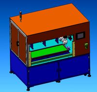
Automatic soldering machine
...automatic soldering machine
3dexport
automatic soldering machine
turbosquid
$10
Solder Tools
...rbosquid
royalty free 3d model solder tools for download as on turbosquid: 3d models for games, architecture, videos. (1624226)
turbosquid
$1
Solderer simple
...squid
royalty free 3d model solderer simple for download as on turbosquid: 3d models for games, architecture, videos. (1171836)
turbosquid
$2
tin for soldering
...free 3d model tin for soldering for download as blend and fbx on turbosquid: 3d models for games, architecture, videos. (1689841)
turbosquid
$1
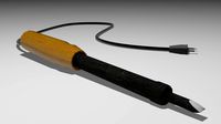
Soldering Iron
...ty free 3d model soldering iron for download as obj and blend on turbosquid: 3d models for games, architecture, videos. (1447146)
3d_export
$15

Solder 3D Model
...model 3dexport solder fusible metal alloy join melt melting soldering iron electronic gun alloys tin lead electrical wire coil...
turbosquid
$14

Soldering iron
...d model soldering iron for download as 3ds, max, obj, and fbx on turbosquid: 3d models for games, architecture, videos. (1389924)
turbosquid
$13
Soldering station
...el soldering station for download as blend, fbx, obj, and stl on turbosquid: 3d models for games, architecture, videos. (1552016)
turbosquid
$5
Steel solder
... available on turbo squid, the world's leading provider of digital 3d models for visualization, films, television, and games.
Clone
3d_export
$5

Clones great republic
...clones great republic
3dexport
clones great republic.those same clones from the star wars movie universe.4 clones available.
3d_export
$10

Clone 3D Model
...clone 3d model
3dexport
clone woman girl female lady chamber sci fi
clone 3d model calcm1 51695 3dexport
turbosquid
$5

Clone machine
... available on turbo squid, the world's leading provider of digital 3d models for visualization, films, television, and games.
archive3d
free

Clone trooper 3D Model
...nd army soldier trooper
clone trooper 2 - 3d model (*.gsm+*.3ds) for interior 3d visualization.
turbosquid
free

Lego Clone Walker
...ree 3d model lego sw clone walker for download as max and fbx on turbosquid: 3d models for games, architecture, videos. (1292252)
turbosquid
$15
Clone trooper helmet
...d model clone trooper helmet for download as ma, obj, and fbx on turbosquid: 3d models for games, architecture, videos. (1199355)
archive3d
free

Clone trooper 3D Model
...and army soldier trooper
clonetrooper 3 - 3d model (*.gsm+*.3ds) for interior 3d visualization.
archive3d
free

Clone trooper 3D Model
...and army soldier trooper
clonetrooper 1 - 3d model (*.gsm+*.3ds) for interior 3d visualization.
3d_ocean
$35

Surface Clone C4D materials
...+ of the most well made materials for maxon’s cinema 4d; on the internet today. each material is crafted with a specific purpo...
turbosquid
$3

Sci-fi cloning vats
...cloning vats for download as 3ds, obj, wrl, x, fbx, and blend on turbosquid: 3d models for games, architecture, videos. (1290168)
Station
3d_export
$5
station
...station
3dexport
station
archibase_planet
free
Station
...station
archibase planet
railroad station railway station bay
railway station n160707 - 3d model for interior 3d visualization.
archibase_planet
free
Station
...station
archibase planet
intercom station equipment
intercom station - 3d model for interior 3d visualization.
archibase_planet
free
Station
...station
archibase planet
station
station n260108 - 3d model (*.gsm+*.3ds) for interior 3d visualization.
3d_export
$5
Station
...station
3dexport
low poly bus station
archibase_planet
free
Station
...station
archibase planet
building station construction
station n170708 - 3d model(*.gsm+*.3ds) for interior 3d visualization.
archibase_planet
free

Station
...station
archibase planet
bus station bus stop
station 1 - 3d model (*.gsm+*.3ds) for interior 3d visualization.
archibase_planet
free

Station
...station
archibase planet
bus station bus stop
station 2 - 3d model (*.gsm+*.3ds) for interior 3d visualization.
archibase_planet
free
Station
...station
archibase planet
bus station bus stop
station 3 - 3d model (*.gsm+*.3ds) for interior 3d visualization.
3d_ocean
$19

Space station
...space station
3docean
space station
space station