Thingiverse
Prusa Z axis, so many problems yet one simple solution ! by MKSA
by Thingiverse
Last crawled date: 3 years ago
Note: This has worked perfectly for more than a year and is still valid. BUT, I wanted to go further and get rid of all the crappy linear bearings and poor leadscrew nuts. Done, I even managed to get rid of the vertical smooth rods, the lead screws can do the job (although TR10 would be more rigid, TR8 are acceptable) see here: https://www.thingiverse.com/thing:2594693
WARNING:
Don't be misled by the negative comments found here. This WORKS ! Unfortunately some people either misunderstand or simply lack the proper knowledge to understand, others are just expressing their anger for my critics of their poor, flawed "things". Just check what these people published and demonstrated. Some even created accounts, nothing published, just to spit their hatred. Amusing :)
PS: Beware, some are crooks, as they tried to call for funding or sell their wares I shot down ! See the first posts below for such piece of human garbage !
+++++++++++++++++++++++++++++++++++++++++++++++++++++++++++++++++++++++
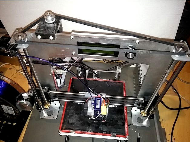
The Prusa configuration is one of the most common, low cost, easy to build 3D printer, yet it has a few flaws and limitation but one that is not acceptable as it is easy to fix, two unsynchronized steppers driving a lead screw at each end of the X carriage. To make things worse, many kits are supplied with regular M5 or M8 threaded rod totally unsuitable for the task ( even often bent !).
You can find a myriad of poor attempts to get rid of the wobble and canted X carriage. Plastic braces to try to constrain the lead screw are just reducing it, not eliminating it.
Auto bed leveling gimmicks are just a waste, often introducing more problems ! And it adds weight (except the IR one from DC42 about the only decent one for the job) ! Note that auto bed leveling almost a must in a non Cartesian machine, is here a poor attempt at compensating a poorly designed, poorly assembled machine with dirt cheap poor quality components ! Better spend your time and money for real solutions.
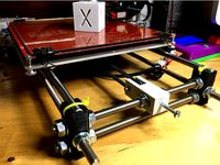
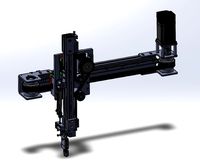
Of course, what I propose is not the first set up making use of one motor, two screws with a closed belt and pulleys to drive them but is the simplest I have seen for a Prusa while allowing to tension the belt despite no idler pulley is used (can't make it simpler :) !)
It is designed for the Geetech Prusa Aluminum but can be adapted to many similar design. I arranged for the belt to be 760mm which is quite easy to find. You can make your own. I did it but it is a bit tricky to explain and do to get an almost professional splice.Here are links giving acceptable results to do it:http://www.thingiverse.com/thing:1814419http://www.thingiverse.com/thing:2162222
Yes, you have to buy two TR8 either 8mm or 2mm lead with nuts, three pulleys but you will save one motor, two couplings (most are so bad you can throw them away) and plenty of headaches and time ! Refuse them if they come bent !
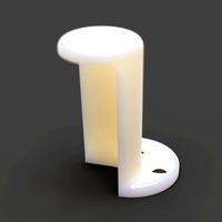
Initially I used ball bearings but switched to Igus bushings I printed (see my other things).
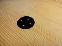
You could even use bronze or delrin bushings reused from old motor, printers ... The ID is 8, OD 12, h 6.. A very common size but for the h, not a big deal if you can use a hacksaw and a file !
Or even print them with PLA, ABS, PETG but how long will they last ?
Although I do not recommend it, if you plan to use ball bearings (needs to make new plate to fit them), keep in mind that as the leadscrew is the moving part it has to be "loctited" to the bearing inner race. Make sure to provide clearance where required too.
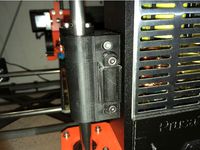
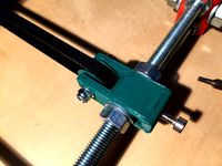
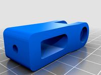
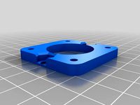
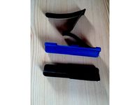
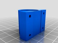
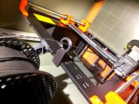
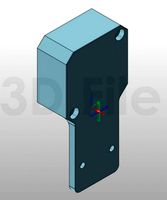
The left and right plates holding the bushings are identical and snap in place on top of the Geeetech top plate. Make sure the smooth rod is about 4 - 5 mm higher to go through the plate with a snug fit.
The plates could be secured by screws or even glued to the aluminum plate underneath but not required in my case as the 8mm guide rods and frame hold them thigh. In addition the belt tension takes up minute play.
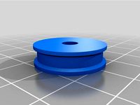
The bushing is 1mm above the plate and the pulley rest on it. Igus plastic is fine against Al.
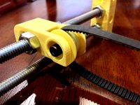
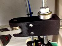
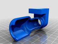
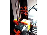
To adjust the belt tension, you just slide the motor holder and secure it with two screws (here I used Nylon M4 but any M4 or similar self tapping screws will do). Just a moderate tension is enough to remove all slack, it doesn't need to be as tight as for the X or Y axis.
Adjust the motor pulley height for proper belt alignment.
I use a 8mm lead screw and three 36 teeth pulleys giving 400 microsteps/mm, 0.04mm per full step, a number I like. As is, the required torque to go up is about 10 N.cm. No big deal for the Nema17 40mm.
I have used it for months now. It is proven solution. It should be easy to adapt to other "metal" Prusa variations. I don't recommend it for "acrylic" or other flimsy frames, these may bend with the belt tension unless reinforced and anyway are junks not worth improving. Sell or give them to people you don't like :)
No wobble, vibration (all my bearings are of my own BTW) and no need to level the bed anymore unless I make change to the bed for ex.
Now I can print decent parts and why not for a more professional design than the Prusa.
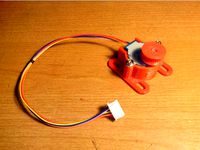
I added a version of motor bracket to be able to mount a PM 48 series stepper one can find in many laser printers. You may need an 3mm ID 5mm OD adapter. Torque is plenty enough for a regular Prusa provided there is no binding or the X carriage doesn't weight like a dead donkey.
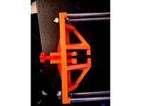
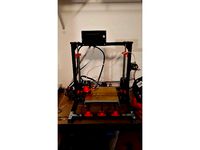
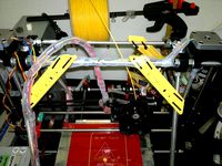
Note that I reinforced the frame as you can see in the picture. Just two Aluminum profiles, bent plate and bolts, attached to the vertical frame and the M10 threaded rods. Many ways to do it, here are some decent solutions. Must be rigid, avoid flimsy plastic parts, makes them beefy. Then you can bolt the whole printer to a heavy thick (40mm) flat piece of old kitchen table top or anything like that.
I even simplified the system by removing the right rod: https://www.thingiverse.com/thing:2504861.
WARNING:
Don't be misled by the negative comments found here. This WORKS ! Unfortunately some people either misunderstand or simply lack the proper knowledge to understand, others are just expressing their anger for my critics of their poor, flawed "things". Just check what these people published and demonstrated. Some even created accounts, nothing published, just to spit their hatred. Amusing :)
PS: Beware, some are crooks, as they tried to call for funding or sell their wares I shot down ! See the first posts below for such piece of human garbage !
+++++++++++++++++++++++++++++++++++++++++++++++++++++++++++++++++++++++
The Prusa configuration is one of the most common, low cost, easy to build 3D printer, yet it has a few flaws and limitation but one that is not acceptable as it is easy to fix, two unsynchronized steppers driving a lead screw at each end of the X carriage. To make things worse, many kits are supplied with regular M5 or M8 threaded rod totally unsuitable for the task ( even often bent !).
You can find a myriad of poor attempts to get rid of the wobble and canted X carriage. Plastic braces to try to constrain the lead screw are just reducing it, not eliminating it.
Auto bed leveling gimmicks are just a waste, often introducing more problems ! And it adds weight (except the IR one from DC42 about the only decent one for the job) ! Note that auto bed leveling almost a must in a non Cartesian machine, is here a poor attempt at compensating a poorly designed, poorly assembled machine with dirt cheap poor quality components ! Better spend your time and money for real solutions.
Of course, what I propose is not the first set up making use of one motor, two screws with a closed belt and pulleys to drive them but is the simplest I have seen for a Prusa while allowing to tension the belt despite no idler pulley is used (can't make it simpler :) !)
It is designed for the Geetech Prusa Aluminum but can be adapted to many similar design. I arranged for the belt to be 760mm which is quite easy to find. You can make your own. I did it but it is a bit tricky to explain and do to get an almost professional splice.Here are links giving acceptable results to do it:http://www.thingiverse.com/thing:1814419http://www.thingiverse.com/thing:2162222
Yes, you have to buy two TR8 either 8mm or 2mm lead with nuts, three pulleys but you will save one motor, two couplings (most are so bad you can throw them away) and plenty of headaches and time ! Refuse them if they come bent !
Initially I used ball bearings but switched to Igus bushings I printed (see my other things).
You could even use bronze or delrin bushings reused from old motor, printers ... The ID is 8, OD 12, h 6.. A very common size but for the h, not a big deal if you can use a hacksaw and a file !
Or even print them with PLA, ABS, PETG but how long will they last ?
Although I do not recommend it, if you plan to use ball bearings (needs to make new plate to fit them), keep in mind that as the leadscrew is the moving part it has to be "loctited" to the bearing inner race. Make sure to provide clearance where required too.
The left and right plates holding the bushings are identical and snap in place on top of the Geeetech top plate. Make sure the smooth rod is about 4 - 5 mm higher to go through the plate with a snug fit.
The plates could be secured by screws or even glued to the aluminum plate underneath but not required in my case as the 8mm guide rods and frame hold them thigh. In addition the belt tension takes up minute play.
The bushing is 1mm above the plate and the pulley rest on it. Igus plastic is fine against Al.
To adjust the belt tension, you just slide the motor holder and secure it with two screws (here I used Nylon M4 but any M4 or similar self tapping screws will do). Just a moderate tension is enough to remove all slack, it doesn't need to be as tight as for the X or Y axis.
Adjust the motor pulley height for proper belt alignment.
I use a 8mm lead screw and three 36 teeth pulleys giving 400 microsteps/mm, 0.04mm per full step, a number I like. As is, the required torque to go up is about 10 N.cm. No big deal for the Nema17 40mm.
I have used it for months now. It is proven solution. It should be easy to adapt to other "metal" Prusa variations. I don't recommend it for "acrylic" or other flimsy frames, these may bend with the belt tension unless reinforced and anyway are junks not worth improving. Sell or give them to people you don't like :)
No wobble, vibration (all my bearings are of my own BTW) and no need to level the bed anymore unless I make change to the bed for ex.
Now I can print decent parts and why not for a more professional design than the Prusa.
I added a version of motor bracket to be able to mount a PM 48 series stepper one can find in many laser printers. You may need an 3mm ID 5mm OD adapter. Torque is plenty enough for a regular Prusa provided there is no binding or the X carriage doesn't weight like a dead donkey.
Note that I reinforced the frame as you can see in the picture. Just two Aluminum profiles, bent plate and bolts, attached to the vertical frame and the M10 threaded rods. Many ways to do it, here are some decent solutions. Must be rigid, avoid flimsy plastic parts, makes them beefy. Then you can bolt the whole printer to a heavy thick (40mm) flat piece of old kitchen table top or anything like that.
I even simplified the system by removing the right rod: https://www.thingiverse.com/thing:2504861.
Similar models
thingiverse
free
Prusa I3 Y Belt tensioner by jamesarm97
...screw and fits 5/16" rods. i also resized the bearing screw hole for an m4 since i am using a belt bearing pulley mod i did.
thingiverse
free
Prusa i3 MK2 X-Idler Tensioner by Jasenk
... kit came with extras that i used.
the pully slide (x-end-idler-front-tensioner) fits one way. if it's tight flip it around.
thingiverse
free
28BYJ-48 supports and pulleys by TheMagusMX
...st the belt is a #6. motors are held in place using small 1/8” screws if you thread the holes or you can use self tapping screws.
thingiverse
free
Prusa i3 Y axis belt tensioner (updated) by HSBallina
...ulley. only needs one 624z bearing. the washers aren't necessary. i actually changed them for a couple of regular m4 washers.
thingiverse
free
Y axis belt tensioner Prusa i3 & 28 teeth synchro pulley by GermanHdez
...ingiverse
y axis belt tensioner for prusa i3 single frame. i use a syncro pulley from ebay (this pulley includes two bearings).
thingiverse
free
Prusa I3 Pro B Frame brace with front plate by Syngenta
... or the idler pulley should be able to rotate freely. the screw shouldn´t be larger than 34mm. i recommend using a 30mm m4 screw.
thingiverse
free
Adjustable Y-Axis Tensioner for i3 by hiptopjones
...39;re good.
additional parts:
pulley with 3mm bearing
m3 screw, washer, and nylock nut (pulley axis)
m4 screw and nut (set screw)
thingiverse
free
Y Axis Upgrade FLSUN Prusa by jmzjamz
...inter's frame, you will have to move one of the beams on the printer. see photos. this will not change the range of movement.
thingiverse
free
Belt driven Z upgrade by MarcusVoss
...idlers)
-two m5x8mm screws and two m5 nuts to mount the kfl008 bearing.
my rod holders: https://www.thingiverse.com/thing:2851231
thingiverse
free
Belt Tensioner - Idle Pulley for Prusa Mendel I2 by Chris918
... old 608 bearing idler on the frame's threaded rod. it is acting as a washer on one side between the nut and the tensioner ;)
Mksa
thingiverse
free
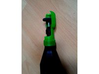
Dremel universal holder by MKSA
...ith a small c clamp. cut or stop the print if you want partial or no protection.
100% infill makes it strong enough without bulk.
thingiverse
free
Sako 300 Win magazine follower by MKSA
... smooth where required for smooth operation.
print in red if you have the filament for. will help see when the magazine is empty.
thingiverse
free
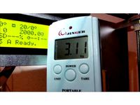
Torque measurement by MKSA
...t your motot can deliver and adjust its current accordingly.
ok, its static, keep that in mind when adjusting your motor current.
thingiverse
free
Silentblock SC8UU by MKSA
...d is not comparable to what i am now getting. biggest gain due to replacing the z lead screws and one motor. see my other things.
thingiverse
free
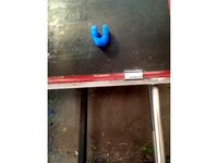
NO SCREW, Hot glue hook by MKSA
...lue gun put a big blob of glue on them and immediately apply to the wall. the glue will go through the 4 holes securing the bond.
thingiverse
free
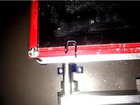
Micro switch bracket for smooth rod. by MKSA
...se petg or abs as it is strong and won't break.
suitable for x and y, for z you need something that provides fine adjustment.
thingiverse
free
Dremel protection by MKSA
...t publishing real working things even remixes i won't have to criticize ? some jerks even have nothing to show, just insults.
thingiverse
free

GT2 Belt tension adjustement by MKSA
...se crappy ones made out of acrylic sheets watch out that it may bend and even break so you now have an excuse to get rid of it :)
thingiverse
free
Simple glass plate holder by MKSA
...p edges that can lead to injury to the eyes or make you bleed ! too much bleeding will cause death. proceed at your own risk. :)
thingiverse
free
Extruder push measurement. by MKSA
...because of thinkverse, not used.
plenty more things to write about but. anyone knowledgeable can fill in the blanks or comment :)
Prusa
turbosquid
$2
Frame Filament Guide Clip-On for Prusa Mk3
...rame filament guide clip-on for prusa mk3 for download as stl on turbosquid: 3d models for games, architecture, videos. (1634730)
3d_export
free
prusa i3 mk3s laser mount for opt lasers
...to learn more about the blue laser technology that conceived the cutting and engraving laser heads from opt lasers, please visit:
turbosquid
free
Prusa small printer adapter holder
...er for download as ipt, skp, dwg, dxf, fbx, ige, obj, and stl on turbosquid: 3d models for games, architecture, videos. (1642936)
3d_export
$30

geisha by jonathan adler
...** i did a 3d printing test in the prusa software, you can find it among the attached images.<br>exchange:<br>.blend...
thingiverse
free

Prusa without Prusa (rc2) by madless
...prusa without prusa (rc2) by madless
thingiverse
just the main part of prusa rc2 faceshield, without writing.
enjoy :)
thingiverse
free
Prusa by acejbc
...prusa by acejbc
thingiverse
prusa knob info
m3 8mm screw
thingiverse
free
Prusa house
...prusa house
thingiverse
how prusa house could look like...
thingiverse
free

Prusa Mk2 "Fake Prusa" LCD cover by anraf1001
...r by anraf1001
thingiverse
version of prusa's lcd cover with "fake prusa" instead of "original prusa"
thingiverse
free
Prusa stabilizator by gutiueugen
...prusa stabilizator by gutiueugen
thingiverse
prusa stabilizator
thingiverse
free
Keychain Prusa by rbarbalho
...keychain prusa by rbarbalho
thingiverse
keychain with text prusa.
Axis
3ddd
$1

Мария Axis
...
3ddd
кухня , классическая , axis
модель кухни.
3d_export
$22
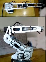
Axis robot 6-axis robotic arm
...ing parts drawings, standard parts purchased parts list, can be produced directly according to the drawings, welcome to download!
3ddd
free

Versatile Axis
...ddd
nexus , плитка
http://bvtileandstone.com/ceramic-porcelain/versatile-axis/
3d_export
$19
robot 2 axis
...robot 2 axis
3dexport
robot 2 axis
turbosquid
$40
Axis R5F
... available on turbo squid, the world's leading provider of digital 3d models for visualization, films, television, and games.
turbosquid
$40
Axis S5F
... available on turbo squid, the world's leading provider of digital 3d models for visualization, films, television, and games.
turbosquid
$30
Axis Athlon
... available on turbo squid, the world's leading provider of digital 3d models for visualization, films, television, and games.
turbosquid
$10

Linear Axis
... available on turbo squid, the world's leading provider of digital 3d models for visualization, films, television, and games.
3d_export
$15

drawing axis
...drawing axis
3dexport
simple rendering of the scene file
3ddd
$1
versatile axis ARC
...versatile axis arc
3ddd
versatile , плитка
versatile axis arc red dot design award
Z
3d_export
$5
nissan z
...nissan z
3dexport
nissan z
3ddd
$1

Vase Z
...vase z
3ddd
vase z
3ddd
$1
полотенцесушить Z
...полотенцесушить z
3ddd
полотенцесушитель
полотенцесушить z
design_connected
free
Z-Chair
...z-chair
designconnected
free 3d model of z-chair designed by karman, aleksei.
design_connected
$11
Z Lamp
...z lamp
designconnected
phillips z lamp computer generated 3d model. designed by kalff, louis.
3d_export
$5
Dragon balls z
...dragon balls z
3dexport
dragon ball z
turbosquid
$20

Fighter Z
...
turbosquid
royalty free 3d model fighter z for download as on turbosquid: 3d models for games, architecture, videos. (1292563)
turbosquid
$9
Pen Z
...pen z
turbosquid
free 3d model pen z for download as obj on turbosquid: 3d models for games, architecture, videos. (1686775)
turbosquid
free
z chair
...z chair
turbosquid
free 3d model z chair for download as max on turbosquid: 3d models for games, architecture, videos. (1410230)
turbosquid
$5

Letter Z
...urbosquid
royalty free 3d model letter z for download as max on turbosquid: 3d models for games, architecture, videos. (1408540)
Problems
3d_export
$5

padma awards
...padma awards
3dexport
thank you for downloading, contact me if you have any problem.
3d_export
$7
automatic test line
.... the relevant parameters and parts of the mechanism can be edited. the mechanism has been verified and the design is reasonable.
3d_export
$12
Tower 3D Model
...tower 3d model
3dexport
tower hide stress problem window stairs
tower 3d model zzzsotti 2460 3dexport
3d_export
free
small table
...small table
3dexport
this is a rustic table for decorating 3d designs.<br>any problem with the design contact me !!
3d_export
free
sarcophagus
...in the zbrash. please contact me if you have problems with the model, i am a novice...
3d_export
$5
princess cut ring
...princess cut ring
3dexport
princess cut ring ready to print ! if you feel any problem so contact me inbox
3d_export
$20
Porsche Boxster S Lava Orange
...used materials from corona library ! if you have problems with model email...
3ddd
$1
Speaker - QUAD ESL 2905
...- quad esl 2905 3ddd колонки sorry for previous problems with studio lighting. i hope this time everything is...
3d_export
$10

Pad for the castle Philips 5100
...g plate for the lock. if the door is recessed deeply , this is not a problem , because you can always use a transition platform .
3d_export
$5
magnifying glass
...3dexport simple magnifying glass design with basic textures<br>i had problems rendering, but the file is in perfect...
Solution
3ddd
$1
Grammer / Solution
... кресло
офисное кресло solution фирмы grammer office. подробнее на www.grammer-office.com
3d_export
$48

TV Solution 3D Model
...solution 3d model
3dexport
tv solution interior dvd decor gypsum cornices spotlights
tv solution 3d model mr.kiwan 19449 3dexport
3d_export
$86
architectural solution 352a1
...architectural solution 352a1
3dexport
3dsmax 2017 3dsmax 2020 fbx obj map
3ddd
$1
Светильник польского производителя Aquaform Lighting Solution
...ution
3ddd
aquaform
светильник польского производителя aquaform lighting solution
модели:
tuba 111x1 distance
tuba 111x2 distance
3d_export
$20
lift internet solutions 3
...ly model of an industrial elevator. - materials are configured in 3ds max and corona render. - formats: fbx, obj, step, max 2020.
3ddd
$1
Светильник польского производителя Aquaform Lighting Solution
...
светильник польского производителя aquaform lighting solution
серия: tuba 111
модели:
tuba 111 on
tuba 111 on 23
tuba 111 on 34
3ddd
$1
Одинарный спот польского производителя Aquaform Lighting Solution
... aquaform
одинарный спот польского производителя aquaform lighting solution
модель: zuma 90
turbosquid
$25

Triple Hair Core Set Shampoo Serum Solution
... shampoo solution serum set for download as max, obj, and fbx on turbosquid: 3d models for games, architecture, videos. (1638904)
3ddd
$1
Поворотный светильник польского производителя Aquaform Lighting Solution
...воротный светильник польского производителя aquaform lighting solutionhttp://www.aquaformlighting.com/
модель: rotto
3ddd
$1
PotteryBarn ROLLING CABINET MEDIA SOLUTION
... телевизор , роллинг
279.4cm wide x 111.8cm high x 12.06cm deep
fits most 152.4cm tvs.
Many
turbosquid
$39
Many Kitchenware
...ty free 3d model many kitchen kitchenware for download as max on turbosquid: 3d models for games, architecture, videos. (1237891)
turbosquid
free
Chair Manie
... available on turbo squid, the world's leading provider of digital 3d models for visualization, films, television, and games.
design_connected
$9

Mani Wall Lamp
...mani wall lamp
designconnected
ligne roset mani wall lamp computer generated 3d model. designed by numéro111.
design_connected
$9
Many Pendant Lamp
...y pendant lamp
designconnected
atelier areti many pendant lamp computer generated 3d model. designed by kerschbaumer, gwendolyn.
3d_export
$15
Many ordinary stones
...many ordinary stones
3dexport
stones
turbosquid
$4
Desert with many objets
...model desert with many objets for download as blend and blend on turbosquid: 3d models for games, architecture, videos. (1682740)
turbosquid
$14
Lamp with many lightbulbs
...l lamp with many lightbulbs for download as max, obj, and fbx on turbosquid: 3d models for games, architecture, videos. (1369910)
turbosquid
$7
Arrmet Mani Wood
...3d model arrmet mani wood for download as obj, fbx, and blend on turbosquid: 3d models for games, architecture, videos. (1218950)
turbosquid
$3

DNA - Many Types
...ree 3d model dna - many types for download as ma, ma, and fbx on turbosquid: 3d models for games, architecture, videos. (1659457)
turbosquid
$5
Kellex Mani Armchair
...ani armchair for download as max, max, 3ds, dwg, fbx, and obj on turbosquid: 3d models for games, architecture, videos. (1655268)
Simple
turbosquid
$1

Simple goblet (Taca simples)
... available on turbo squid, the world's leading provider of digital 3d models for visualization, films, television, and games.
3d_export
$5
simple bench
...simple bench
3dexport
the simple bench which can be used in simple projects or video-games.
3d_export
$5
simple knob
...simple knob
3dexport
simple knob
3d_export
$5
simple handle
...simple handle
3dexport
simple handle
3d_export
$5
simple button
...simple button
3dexport
simple button
3d_export
$5
simple spindle
...simple spindle
3dexport
simple spindle
3d_export
$5

simple wheel
...simple wheel
3dexport
simple wheel
3d_export
$5
simple chair
...simple chair
3dexport
simple blue chair
3d_export
free

Simple room
...simple room
3dexport
here is a simple but beautiful room
3ddd
free

SIMPLE | Кресло
...io cianfarra , simple
производитель area declic дизайн giulio cianfarra коллекция simple
One
turbosquid
$2
one plus one
... available on turbo squid, the world's leading provider of digital 3d models for visualization, films, television, and games.
3ddd
$1
One
...one
3ddd
стул
офисный стул one
3ddd
free

one
...
palazetti one ,http://palazzetti.ca/index.php/component/virtuemart/seating/armchairs-lounges/one-chair-detail?itemid=0
turbosquid
$35

One A
... available on turbo squid, the world's leading provider of digital 3d models for visualization, films, television, and games.
turbosquid
free
One
... available on turbo squid, the world's leading provider of digital 3d models for visualization, films, television, and games.
3ddd
$1
Стул One
...стул one
3ddd
one , magis
кресло magis s.p.a , one
3ddd
$1
Стул One
...стул one
3ddd
one , magis
кресло one chair (4star), magis s.p.a.
3d_export
$20

xbox one
...xbox one
3dexport
xbox one
3ddd
$1
xbox one
... консоль , джойстик
xbox one + kinect + gamepad
3ddd
free
One
...nstantin grcic
артикул ct-284 (cosmorelax.ru)
размер l36xw41xh82.5, sh 77cm
цвет черный, красный
материал алюминий
вес 2,5 кг