Thingiverse
Prusa MK3 X axis RPI Camera Mount by MoonDoggy
by Thingiverse
Last crawled date: 3 years ago
Update: 2018/04/09: Added new Ball Mount and Cable Guide to work with new R2 Prusa part revisions. All other parts unaffected. Parts named and watermarked with R2.
Update: 2018/02/13: Added a Ball Link with support for camera cable.
This is a Ball and Socket based RPi camera mount for use with the RPi Zero directly attached to a Prusa i3 MK3. This project compliments my MK3 Einsy RPi Zero Access project. https://www.thingiverse.com/thing:2734810.
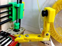
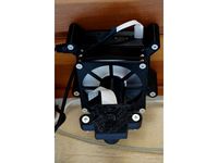
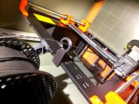
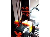
It mounts the RPi camera on the X-axis stepper, keeping the camera relative to the hot end, no mater the project height. The camera only moves when the Z-axis changes, so less weight to effect the print, compared to mounting on the bed. The camera can then be positioned high, low, close or far, based on the amount of ball socket links added.
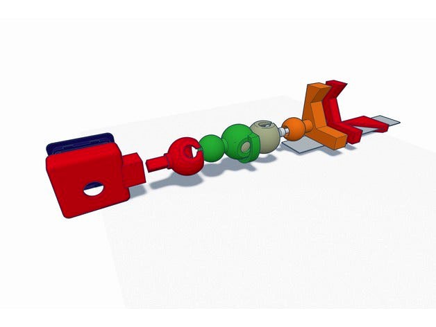
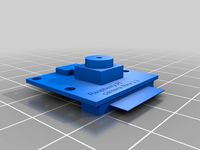
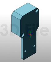
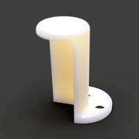
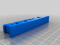
There are two pieces that sandwich together and mount on the X-stepper. The Camera Arm Ball faces forward, and holds the additional links, and the the camera. The Cable Guide supports the camera cable under the stepper, and guides the camera cable over the X-axis stepper loom.
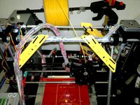
New Ball Link with Support: The camera cable was sagging under the chain of ball links, and still being unruly. A new Ball Link with a support was added to clip the cable into and keep it tucked up against the chain of ball links. The support is open on one side, so it can be snapped into the chain, and not require undoing the camera cable. Only a couple of these links should be required.
If using with a Prusa MK3, and the attached RPi Zero, the cable guide also helps keep the camera cable out of the way, and routes cleanly to the adapter board, required to use a camera with the smaller RPI Zero camera cable. See https://www.thingiverse.com/thing:2734810.
The brackets that mount on the X-axis stepper were reworked from files on Prusa's github project.
The Ball Socket Link was rotated 1%, so it would sit flat on the build plate.
The Camera Mount was broken apart, to remove an unnecessary part, and open it up, for easier focusing.
The Camera Ball Stud and the Camera Ball Socket were reworked form the original Ball Socket Link.
Assembly
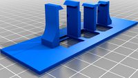
Order the parts just as shown in first picture.
Run a m3x20mm screw through the Camera Arm Ball opening, through the Cable Guide, and into the open hole on the X-axis stepper.
Route the camera cable through the guide.
Attach the front end of the cable to the RPi camera.
Attach the rear end of the cable to the cable adapter, connected to the mini cable and RPi Zero.
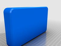
Mount camera in housing and snap on the back. If it isn't tight add a drop of glue, or piece of tape.
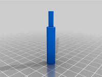
Add as many Ball Socket Links as needed to position the camera where desired.
The camera cable in my pictures is 24" long, and seems just about perfect.
The Adafruit adapter required to lengthen the short mini camera cable is https://www.adafruit.com/product/3671.
Update: 2018/02/13: Added a Ball Link with support for camera cable.
This is a Ball and Socket based RPi camera mount for use with the RPi Zero directly attached to a Prusa i3 MK3. This project compliments my MK3 Einsy RPi Zero Access project. https://www.thingiverse.com/thing:2734810.
It mounts the RPi camera on the X-axis stepper, keeping the camera relative to the hot end, no mater the project height. The camera only moves when the Z-axis changes, so less weight to effect the print, compared to mounting on the bed. The camera can then be positioned high, low, close or far, based on the amount of ball socket links added.
There are two pieces that sandwich together and mount on the X-stepper. The Camera Arm Ball faces forward, and holds the additional links, and the the camera. The Cable Guide supports the camera cable under the stepper, and guides the camera cable over the X-axis stepper loom.
New Ball Link with Support: The camera cable was sagging under the chain of ball links, and still being unruly. A new Ball Link with a support was added to clip the cable into and keep it tucked up against the chain of ball links. The support is open on one side, so it can be snapped into the chain, and not require undoing the camera cable. Only a couple of these links should be required.
If using with a Prusa MK3, and the attached RPi Zero, the cable guide also helps keep the camera cable out of the way, and routes cleanly to the adapter board, required to use a camera with the smaller RPI Zero camera cable. See https://www.thingiverse.com/thing:2734810.
The brackets that mount on the X-axis stepper were reworked from files on Prusa's github project.
The Ball Socket Link was rotated 1%, so it would sit flat on the build plate.
The Camera Mount was broken apart, to remove an unnecessary part, and open it up, for easier focusing.
The Camera Ball Stud and the Camera Ball Socket were reworked form the original Ball Socket Link.
Assembly
Order the parts just as shown in first picture.
Run a m3x20mm screw through the Camera Arm Ball opening, through the Cable Guide, and into the open hole on the X-axis stepper.
Route the camera cable through the guide.
Attach the front end of the cable to the RPi camera.
Attach the rear end of the cable to the cable adapter, connected to the mini cable and RPi Zero.
Mount camera in housing and snap on the back. If it isn't tight add a drop of glue, or piece of tape.
Add as many Ball Socket Links as needed to position the camera where desired.
The camera cable in my pictures is 24" long, and seems just about perfect.
The Adafruit adapter required to lengthen the short mini camera cable is https://www.adafruit.com/product/3671.
Similar models
thingiverse
free

Prusa i3 MK3 x axis drag chain holder by KevinTheGoalie
...er guide. other parts seem like they should still fit on the mk3. not tested yet, so if you make it please comment if it works!
thingiverse
free

Raspberry PI Zero W and camera v2 Mount for Original Prusa MK3 by alessandroame
...ry (see last photo)
more photos here: http://aame.work/2018/02/05/raspberry-pi-zero-w-and-camera-v2-mount-for-original-prusa-mk3/
thingiverse
free

RPi Camera Arm Updated for MK3 new X-Carriage Part by blackbarlow
...w it fits. this change was only made on the cable guide and camera ball arm parts, the other parts are the same as the original.
thingiverse
free

Prusa i3 MK2S MK3 X stepper motor strain relief w/ camera mount by UltiMike
...cture.
made it to guide the cable to the back not as few i found to the side
user m3x18mm screw, same as the original for x motor
thingiverse
free

Screw base Cam Prusa MK3/MK3s Camera mount by Timandtina
...ced arm to allow for a webcam that has the screw hole base. this will fit on the x-axis stepper motor on the prusa mk3 and mk3s.
thingiverse
free

Prusa i3 MK3 X-axis-cable holder by ad_lamy
...n solution will conflict with the mmu, but i wanted to keep the zip-tie free and practical design with the original cables mount.
thingiverse
free

Prusa MK3S Pi Camera V2.1 Mount With Optional X Axis Cable Strain Relief by tinkr3d
... printer
optional x axis cable strain relief
required :
1 - wire tie 165x2.5 mm
1 - m3 x 18 bolt
(both found in mk3s spare parts)
thingiverse
free

Original PRUSA MK3 Cable chain mod Rework by ad_lamy
...and flexible sleeve on x-axis in view to manage space for the mmu2, i think the mmu is non-compliant with the x-axis chain cable.
thingiverse
free

Support fort Raspberry PI Zero Module Cam on Prusa I3 MK3S by Eric_Lotre
...verse
just my design of a rasberry pi zero module camera mount for the prusa i3 mk3s for use with the short original cable !!!!!
thingiverse
free

Open Cable X-Axis Cable Chain Mount for Hictop Prusa i3 by jimmythekayaker
...oving the ends from the wiring harness.
i am currently using it with this cable chain: https://www.thingiverse.com/thing:611593
Moondoggy
thingiverse
free

Prusa MK3 Einsey Raspberry Pi Zero Octopi Case Remix by Kevin-Halbert
...the info on this design from the original source "moondoggy" this is a remix of a great design by...
thingiverse
free

Prusa MK3 Einsy RPi Zero Access by MoonDoggy
...per. https://www.thingiverse.com/thing:2773810
notice: license changed to gnu gpl, to match prusa's original source license.
thingiverse
free

C270 Mount for 3030 Extrusion Ball Link Camera Mount by zcubed
...second attaches from the side which is compatible with moondoggy#39;s design. note: if you use any lens attachments on...
thingiverse
free

MK3 Pi Camera Ball and Socket Support by RainyDayHiker
...by rainydayhiker thingiverse i really liked the design of moondoggy#39;s ball and socket links but i didn't want to...
thingiverse
free

3030 Extrusion Pi Camera Mount by zcubed
...zcubed thingiverse i liked the ball joint flexibility of moondoggy#39;s pi cam design but didn't want to attach it...
Rpi
3d_export
$5
Rasberry PI 3D Model
...rasberry pi 3d model 3dexport rpi model electronics case gadget 3dprinting printing rasberry pi 3d...
thingiverse
free

rpi case by ekinghao
...rpi case by ekinghao
thingiverse
rpi case
thingiverse
free
Rpi Case by sgehman
...rpi case by sgehman
thingiverse
rpi case
thingiverse
free
RPI / RPI-WW Cam Holder by TobyTetzi123
...spberry-pi-rpi-wwcam/p/30037327
regards toby
edit:
4th. picture shows rpi-ww cam
5th. picture shows rpi cam
at the same position.
thingiverse
free

rpi by Jylehr
...rpi by jylehr
thingiverse
a rack
thingiverse
free
RPi Camera 5MP v1.3
...rpi camera 5mp v1.3
thingiverse
rpi camera 5mp v1.3
thingiverse
free
RPi Tower Stand by shri3k
...rpi tower stand by shri3k
thingiverse
a minimal tower mount for rpi.
tested with rpi4
thingiverse
free
RPi Fan Cam by Edd77
...rpi fan cam by edd77
thingiverse
rpi fan camhttps://www.thingiverse.com/thing:2835318
thingiverse
free
RPi screen back by audiofreak9
...rpi screen back by audiofreak9
thingiverse
from mcm electronics, this is a back for the rpi screen
thingiverse
free
KIS-RPI 234 (mount for rack) by legalized
...its for rpi 2, rpi 3, rpi 4
drill holes for fittings or modify the thing so it works for you.. this can also be used as a stand..
Mk3
turbosquid
$50
cention mk3
...ty free 3d model cention mk3 for download as ma, obj, and fbx on turbosquid: 3d models for games, architecture, videos. (1454148)
turbosquid
$129
MK3 Tank
... available on turbo squid, the world's leading provider of digital 3d models for visualization, films, television, and games.
turbosquid
$100

Toyota Supra MK3
... available on turbo squid, the world's leading provider of digital 3d models for visualization, films, television, and games.
turbosquid
$44
cention mk3 low poly
...d model cention mk3 low poly for download as ma, obj, and fbx on turbosquid: 3d models for games, architecture, videos. (1454666)
turbosquid
$30
Challenger I Mk3 Falcon
... available on turbo squid, the world's leading provider of digital 3d models for visualization, films, television, and games.
turbosquid
$10

American Frag hand grenade MK3
...free 3d model american frag hand grenade mk3 for download as on turbosquid: 3d models for games, architecture, videos. (1393624)
turbosquid
$20
Mk3 US Navy Combat Knife
...ty free 3d model mk3 us navy combat knife for download as fbx on turbosquid: 3d models for games, architecture, videos. (1172791)
3d_export
$29

Ford Fiesta MK3 Modified 3D Model
...7 tumerfx mtumer mehmet t?mer 1993 1995 1996 wrc special modifed modifiye
ford fiesta mk3 modified 3d model mtumer 30698 3dexport
3d_export
$99

Toyota Supra Mk3 19861993 3D Model
...ort fast coupe japan 1986 1987 1988 1989 1990 1991 1992 1993 tuning turbo
toyota supra mk3 19861993 3d model squir 62530 3dexport
turbosquid
$5

Timothy Oulton Mars Chair MK3
...on mars chair mk3 for download as 3ds, max, obj, fbx, and dae on turbosquid: 3d models for games, architecture, videos. (1209782)
Prusa
turbosquid
$2
Frame Filament Guide Clip-On for Prusa Mk3
...rame filament guide clip-on for prusa mk3 for download as stl on turbosquid: 3d models for games, architecture, videos. (1634730)
3d_export
free
prusa i3 mk3s laser mount for opt lasers
...to learn more about the blue laser technology that conceived the cutting and engraving laser heads from opt lasers, please visit:
turbosquid
free
Prusa small printer adapter holder
...er for download as ipt, skp, dwg, dxf, fbx, ige, obj, and stl on turbosquid: 3d models for games, architecture, videos. (1642936)
3d_export
$30

geisha by jonathan adler
...** i did a 3d printing test in the prusa software, you can find it among the attached images.<br>exchange:<br>.blend...
thingiverse
free

Prusa without Prusa (rc2) by madless
...prusa without prusa (rc2) by madless
thingiverse
just the main part of prusa rc2 faceshield, without writing.
enjoy :)
thingiverse
free
Prusa by acejbc
...prusa by acejbc
thingiverse
prusa knob info
m3 8mm screw
thingiverse
free
Prusa house
...prusa house
thingiverse
how prusa house could look like...
thingiverse
free

Prusa Mk2 "Fake Prusa" LCD cover by anraf1001
...r by anraf1001
thingiverse
version of prusa's lcd cover with "fake prusa" instead of "original prusa"
thingiverse
free
Prusa stabilizator by gutiueugen
...prusa stabilizator by gutiueugen
thingiverse
prusa stabilizator
thingiverse
free
Keychain Prusa by rbarbalho
...keychain prusa by rbarbalho
thingiverse
keychain with text prusa.
Axis
3ddd
$1

Мария Axis
...
3ddd
кухня , классическая , axis
модель кухни.
3d_export
$22
Axis robot 6-axis robotic arm
...ing parts drawings, standard parts purchased parts list, can be produced directly according to the drawings, welcome to download!
3ddd
free

Versatile Axis
...ddd
nexus , плитка
http://bvtileandstone.com/ceramic-porcelain/versatile-axis/
3d_export
$19
robot 2 axis
...robot 2 axis
3dexport
robot 2 axis
turbosquid
$40
Axis R5F
... available on turbo squid, the world's leading provider of digital 3d models for visualization, films, television, and games.
turbosquid
$40
Axis S5F
... available on turbo squid, the world's leading provider of digital 3d models for visualization, films, television, and games.
turbosquid
$30

Axis Athlon
... available on turbo squid, the world's leading provider of digital 3d models for visualization, films, television, and games.
turbosquid
$10

Linear Axis
... available on turbo squid, the world's leading provider of digital 3d models for visualization, films, television, and games.
3d_export
$15

drawing axis
...drawing axis
3dexport
simple rendering of the scene file
3ddd
$1
versatile axis ARC
...versatile axis arc
3ddd
versatile , плитка
versatile axis arc red dot design award
Camera
archibase_planet
free
Camera
...base planet
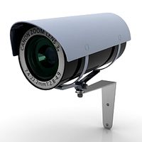
camera surveillance camera video camera
camera surveillance n090211 - 3d model (*.3ds) for interior 3d visualization.
archibase_planet
free

Camera
...hibase planet
camera security camera video camera
camera security n210515 - 3d model (*.gsm+*.3ds) for exterior 3d visualization.
archibase_planet
free
Camera
...se planet
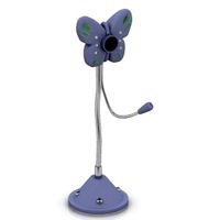
camera web camera webcam
camera butterfly usb pc camera n090713 - 3d model (*.gsm+*.3ds) for interior 3d visualization.
archibase_planet
free
Camera
...mera
archibase planet
surveillance camera video camera camcorder
camera n011211 - 3d model (*.3ds) for exterior 3d visualization.
archibase_planet
free
Camera
...camera
archibase planet
camera digital camera
camera canon digital n041211 - 3d model (*.3ds) for interior 3d visualization.
archibase_planet
free
Camera
...camera
archibase planet
camera film camera phototechnique
camera n100214 - 3d model (*.gsm+*.3ds) for interior 3d visualization.
archibase_planet
free
Camera
...amera
archibase planet
camera video camera camcorder
camera video n070315 - 3d model (*.gsm+*.3ds) for interior 3d visualization.
archibase_planet
free

Camera
...rchibase planet
camera video camera camcorder
camera studio n101213 - 3d model (*.gsm+*.3ds+*.max) for interior 3d visualization.
archibase_planet
free
Camera
...ibase planet
digital camera camera phototechnique
camera canon ixus 400 n310311 - 3d model (*.3ds) for interior 3d visualization.
archibase_planet
free

Camera
...ase planet
photocamera video camera camera
camera sony t300 black n291010 - 3d model (*.gsm+*.3ds) for interior 3d visualization.
Mount
3d_export
free

mounting bracket
...mounting plate is the portion of a hinge that attaches to the wood. mounting plates can be used indoors, cabinetry and furniture.
turbosquid
$2

MOUNTING
... available on turbo squid, the world's leading provider of digital 3d models for visualization, films, television, and games.
turbosquid
free

Mounts
... available on turbo squid, the world's leading provider of digital 3d models for visualization, films, television, and games.
turbosquid
free

Mount Fuji
...fuji
turbosquid
free 3d model mount fuji for download as obj on turbosquid: 3d models for games, architecture, videos. (1579977)
3d_export
$5

Headphone mount LR
...headphone mount lr
3dexport
headphone mount l+r
turbosquid
$39

Mount rainier
...quid
royalty free 3d model mount rainier for download as fbx on turbosquid: 3d models for games, architecture, videos. (1492586)
turbosquid
$5

pipe mounting
...quid
royalty free 3d model pipe mounting for download as obj on turbosquid: 3d models for games, architecture, videos. (1293744)
turbosquid
$3

Mounting Tires
...uid
royalty free 3d model mounting tires for download as fbx on turbosquid: 3d models for games, architecture, videos. (1708511)
3d_export
$5

Magnetic GoPro Mount
...pro mount
3dexport
cool magnetic mount for gopro. allows you to mount the camera on flat metal surfaces and get exclusive shots.
turbosquid
$5

Stone Mount
...ty free 3d model stone mount for download as ma, obj, and fbx on turbosquid: 3d models for games, architecture, videos. (1370306)