Thingiverse

Prusa Lights with Clip-On Brackets by LBussy
by Thingiverse
Last crawled date: 4 years, 1 month ago
A remix of Prusa Lights (using WAGO connectors). That project was in turn inspired by:
Prusa I3 MK2 Frame Holder Collection: 2 LED light holder by wschadow
Prusa Switch Box by Aeggsbaerde
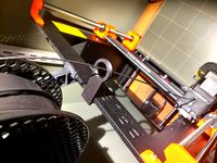
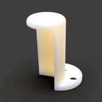
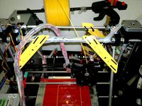
A modification to the light mounts was necessary to clear the filament spools. As designed, the original was fitted on a printer with the MMU upgrade, which I do not have. The clip-on brackets should work with or without the MMU setup. The inspirational project also used longer screws threaded through the Z-axis caps. The clips avoid taking that apart.
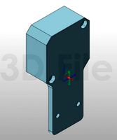
The "lightbox" sides were beefed up a bit as they would sometimes peel up or warp during printing since the sides cooled before the top was complete. This change necessitated additional changes to the top and bottom lightbox lids, as well as the mounting mechanism to the brackets.
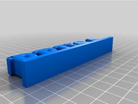
A square nut slot and a hex nut recess were added to the lightbox top cover to make the mounting more substantial vs. the original, which had threads in the print. The bottom has been changed to three screws instead of a snap-fit. These are threaded into the plastic as there is no structural strength needed.
As shown (one lightbox on each side of the printer and the switch box), you would need:
4 x 12V Car 1210 48SMD LED
5 x WAGO 221-413 3 Way (2 for each side, 1 in the switch)
1 x WAGO 221-415 5 Way (1 in the switch)
1 x HOTSYSTEM DC12V 20A Round Rocker Toggle Switch ON-OFF
1 x 12V power supply
2 x M3 square nuts (one in each lightbox)
2 x M3 hex nuts (one in each lightbox)
4 x M3*12mm to mount lightbox to brackets (two in each lightbox)
6 x M3*6mm to affix the bottom cover to the lightbox (three in each lightbox)
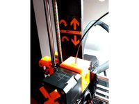
2 x M312mm to replace the M39mm screws which will be used to affix the switch box to the Z-motor
Miscellaneous electric wiring (I used 20 gauge stranded black and red)
Carefully break off the black plastic which holds the pins on the wires connecting the LEDs. You will use the pins inside the Wago connectors.
The 5-way Wago is used in the switch box for the ground pins in the switchbox, there will be one place left over. A three-way will be used for power.
You must solder the cables to the switch as there is not enough depth in the box to use crimp on female spades. For the rest, the wires clamp into the Wago connectors. I used male Dupont pins crimped on all of the wire ends as they fit all the way into the Wagos and provided a more secure connection.
Prusa I3 MK2 Frame Holder Collection: 2 LED light holder by wschadow
Prusa Switch Box by Aeggsbaerde
A modification to the light mounts was necessary to clear the filament spools. As designed, the original was fitted on a printer with the MMU upgrade, which I do not have. The clip-on brackets should work with or without the MMU setup. The inspirational project also used longer screws threaded through the Z-axis caps. The clips avoid taking that apart.
The "lightbox" sides were beefed up a bit as they would sometimes peel up or warp during printing since the sides cooled before the top was complete. This change necessitated additional changes to the top and bottom lightbox lids, as well as the mounting mechanism to the brackets.
A square nut slot and a hex nut recess were added to the lightbox top cover to make the mounting more substantial vs. the original, which had threads in the print. The bottom has been changed to three screws instead of a snap-fit. These are threaded into the plastic as there is no structural strength needed.
As shown (one lightbox on each side of the printer and the switch box), you would need:
4 x 12V Car 1210 48SMD LED
5 x WAGO 221-413 3 Way (2 for each side, 1 in the switch)
1 x WAGO 221-415 5 Way (1 in the switch)
1 x HOTSYSTEM DC12V 20A Round Rocker Toggle Switch ON-OFF
1 x 12V power supply
2 x M3 square nuts (one in each lightbox)
2 x M3 hex nuts (one in each lightbox)
4 x M3*12mm to mount lightbox to brackets (two in each lightbox)
6 x M3*6mm to affix the bottom cover to the lightbox (three in each lightbox)
2 x M312mm to replace the M39mm screws which will be used to affix the switch box to the Z-motor
Miscellaneous electric wiring (I used 20 gauge stranded black and red)
Carefully break off the black plastic which holds the pins on the wires connecting the LEDs. You will use the pins inside the Wago connectors.
The 5-way Wago is used in the switch box for the ground pins in the switchbox, there will be one place left over. A three-way will be used for power.
You must solder the cables to the switch as there is not enough depth in the box to use crimp on female spades. For the rest, the wires clamp into the Wago connectors. I used male Dupont pins crimped on all of the wire ends as they fit all the way into the Wagos and provided a more secure connection.
Similar models
grabcad
free

Wago 221-413 3 Wire Lever-Nut
...wago 221-413 3 wire lever-nut
grabcad
wago 221-413 3 wire lever-nut connector
grabcad
free

Wago 221-412 2 Wire Lever-Nut
...wago 221-412 2 wire lever-nut
grabcad
wago 221-412 2 wire connector / wire nut, end splice.
thingiverse
free

Power Supply Cover for Prusa Clone by jaimealbq
...witch and ac plug, screwing by side.
extra material
2 x m3 10mm screw
2 x m3 nut
1 x kcd1 switch
1 x 3 pins ac plug c14
some wire
thingiverse
free

Z Stop Adjuster
...itch to affix new bracket.
other items required.
1x m3 x 25-30mm bolt
1x m3 nut
2x m3 bolts or grub screws to affix upper bracket
grabcad
free

Wago 221-415 Connector x 5 Mount
...nd this design useful, too.
remember to leave me some feedback or even a tip to keep me enthused to make more of these drawings.
grabcad
free

Wago 221 Connector Universal Mount
...nd this design useful, too.
remember to leave me some feedback or even a tip to keep me enthused to make more of these drawings.
grabcad
free

Wago 221-615 5 Wire Lever-Nut
...erating levers; 10 awg; transparent housing
https://www.wago.com/us/wire-splicing-connectors/compact-splicing-connector/p/221-615
grabcad
free

Wago 221-413 Mount
...nd this design useful, too.
remember to leave me some feedback or even a tip to keep me enthused to make more of these drawings.
grabcad
free

Wago 221 DIN rail mount
...wago 221 din rail mount
grabcad
din rail mount for wago 221 connectors
thingiverse
free

Anderson connector half-bracket by DavidTruett
...e thread, and the nut and the tail of the screw are both fully enclosed in the finished assembly (for electrical safety reasons).
Lbussy
thingiverse
free

Flitesense Keg Tower Cap by LBussy
...ay and the stability provided.
design available here: https://www.tinkercad.com/things/hepth1kv1bp-flitesense-tap-tower-cap/edit
thingiverse
free

Battery Tray by LBussy
...s one is not perfect for you, you can start with this and customize it in tinkercad:
https://www.tinkercad.com/things/29ejyeobuy5
thingiverse
free

Case for Buck Converter with LCD Display by LBussy
...ound this necessary, i did not need it with petg.
this uses 4 hex head m3 x 16mm screws to sandwich the board and close the case.
thingiverse
free

Case for SONOFF WiFi Switch Module by LBussy
...intended to be printed with the bottom layer in concentric rings to allow tear-off.
4 x m3 x 20mm allen-head screws are required.
thingiverse
free

BrewPi Remix Case Without Standoffs by Adrianoftyiel
...case without standoffs by adrianoftyiel thingiverse a remix of lbussy#39;s case with the standoffs and arduino connector holes removed...
thingiverse
free

Modified Parametric Box with Lid by Apofus67
...apofus67 thingiverse needed a box for something and saw lbussy#39;s box. http://www.thingiverse.com/thing:1918169 i had played a bit with openscad...
thingiverse
free

Duplicating House Keys Credit Card (Remix) by Regnad
...will need to print the key guage posted by lbussy http://www.thingiverse.com/thing:2086917 once that is printed, you need to get...
Prusa
turbosquid
$2
Frame Filament Guide Clip-On for Prusa Mk3
...rame filament guide clip-on for prusa mk3 for download as stl on turbosquid: 3d models for games, architecture, videos. (1634730)
3d_export
free
prusa i3 mk3s laser mount for opt lasers
...to learn more about the blue laser technology that conceived the cutting and engraving laser heads from opt lasers, please visit:
turbosquid
free
Prusa small printer adapter holder
...er for download as ipt, skp, dwg, dxf, fbx, ige, obj, and stl on turbosquid: 3d models for games, architecture, videos. (1642936)
3d_export
$30

geisha by jonathan adler
...** i did a 3d printing test in the prusa software, you can find it among the attached images.<br>exchange:<br>.blend...
thingiverse
free

Prusa without Prusa (rc2) by madless
...prusa without prusa (rc2) by madless
thingiverse
just the main part of prusa rc2 faceshield, without writing.
enjoy :)
thingiverse
free
Prusa by acejbc
...prusa by acejbc
thingiverse
prusa knob info
m3 8mm screw
thingiverse
free
Prusa house
...prusa house
thingiverse
how prusa house could look like...
thingiverse
free

Prusa Mk2 "Fake Prusa" LCD cover by anraf1001
...r by anraf1001
thingiverse
version of prusa's lcd cover with "fake prusa" instead of "original prusa"
thingiverse
free
Prusa stabilizator by gutiueugen
...prusa stabilizator by gutiueugen
thingiverse
prusa stabilizator
thingiverse
free
Keychain Prusa by rbarbalho
...keychain prusa by rbarbalho
thingiverse
keychain with text prusa.
Brackets
archibase_planet
free
Bracket
...bracket
archibase planet
bracket corbel holder
bracket 1 - 3d model (*.gsm+*.3ds) for interior 3d visualization.
archibase_planet
free
Bracket
...bracket
archibase planet
bracket corbel console
bracket 5 - 3d model (*.gsm+*.3ds) for interior 3d visualization.
archibase_planet
free
Bracket
...bracket
archibase planet
corbel holder bracket
bracket 6 - 3d model (*.gsm+*.3ds) for interior 3d visualization.
archibase_planet
free
Bracket
...bracket
archibase planet
bracket corbel console
bracket 8 - 3d model (*.gsm+*.3ds) for interior 3d visualization.
archibase_planet
free

Bracket
...bracket
archibase planet
bracket corbel holder
bracket n280911 - 3d model (*.gsm+*.3ds) for interior 3d visualization.
archibase_planet
free
Bracket
...bracket
archibase planet
holder corbel bracket
bracket 9 - 3d model (*.gsm+*.3ds) for interior 3d visualization.
archibase_planet
free
Bracket
...bracket
archibase planet
corbel holder bracket
bracket 10 - 3d model (*.gsm+*.3ds) for interior 3d visualization.
archibase_planet
free
Bracket
...bracket
archibase planet
corbel console bracket
bracket 11 - 3d model (*.gsm+*.3ds) for interior 3d visualization.
archibase_planet
free
Bracket
...bracket
archibase planet
holder console bracket
bracket 12 - 3d model (*.gsm+*.3ds) for interior 3d visualization.
archibase_planet
free
Bracket
...bracket
archibase planet
bracket corbel holder
bracket 13 - 3d model (*.gsm+*.3ds) for interior 3d visualization.
Clip
archibase_planet
free

Clip
...clip
archibase planet
paper-clip clip office equipment
clip band - 3d model for interior 3d visualization.
3d_export
$5
screw clip
...screw clip
3dexport
screw clip
3d_ocean
$4
Butterfly clip
... a butterfly clip, it comes with a ready to render set for out of the box rendering. obj version and max alones version included.
turbosquid
$2

clip
...
royalty free 3d model clip for download as ma, obj, and fbx on turbosquid: 3d models for games, architecture, videos. (1358622)
turbosquid
$5

Clip
...lty free 3d model clip for download as c4d, 3ds, fbx, and obj on turbosquid: 3d models for games, architecture, videos. (1521355)
turbosquid
$19
Clip
... available on turbo squid, the world's leading provider of digital 3d models for visualization, films, television, and games.
turbosquid
$4
Clips
... available on turbo squid, the world's leading provider of digital 3d models for visualization, films, television, and games.
turbosquid
$3
clip
... available on turbo squid, the world's leading provider of digital 3d models for visualization, films, television, and games.
turbosquid
$2

clips
... available on turbo squid, the world's leading provider of digital 3d models for visualization, films, television, and games.
turbosquid
free

Clip
... available on turbo squid, the world's leading provider of digital 3d models for visualization, films, television, and games.
Lights
archibase_planet
free
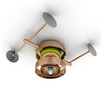
Light
...light
archibase planet
lamp lighting light
light - s2 - 3d model for interior 3d visualization.
archibase_planet
free

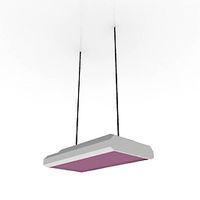
Light
...light
archibase planet
light luminaire lighting
light l0465 - 3d model (*.gsm+*.3ds) for interior 3d visualization.
3d_export
$5
lighting
...lighting
3dexport
lighting
3d_export
$5

lighting
...lighting
3dexport
lighting in livingroom
turbosquid
$3
Lighting Tree with Lights
...d model lighting tree with lights for download as max and 3ds on turbosquid: 3d models for games, architecture, videos. (1585507)
archibase_planet
free
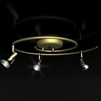
Light
...light
archibase planet
luster lighting solution
light - s - 3d model for interior 3d visualization.
archibase_planet
free
Light
...light
archibase planet
luster lamp lighting
light 1 - 3d model for interior 3d visualization.
archibase_planet
free
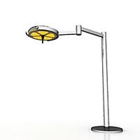
Lights
...lights
archibase planet
surgical lights surgical lamp
surgical lights (floor) - 3d model for interior 3d visualization.
archibase_planet
free
Light
...light
archibase planet
lighting luminaire candlelight
light l0463 - 3d model (*.gsm+*.3ds) for interior 3d visualization.
3d_export
$18
street light-lighting-light-xia bing
...
3dexport
street light-lighting-light-xia bing<br>max 2015 v-ray 3 max 2015<br>textures<br>all files in zip...