Thingiverse
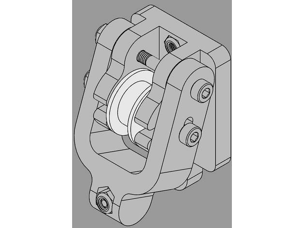
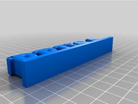
Prusa I3 MK3 Y axis Adjustable Belt Tensioner by MattyVee
by Thingiverse
Last crawled date: 3 years ago
Update 4/22/19 - mk3s support - It was brought to my attention that the new belt holder/tensioner used on the mk3s is not compatible with this belt tensioner. The easiest and in my opinion the best solution to using my belt tensioner on the mk3s would be to print the original belt holder used on the mk3 since it is a direct bolt in. Additionally having my tensioner with the mk3s holder/tensioner is redundant and a potential source of belt loosening over time. I have uploaded the most current mk3 belt holder so you won't need to go searching for it.
Update 3/10/18 - I used jzkmath model of the assembled prusa i3 mk3 with the r2 components and found that the tensioner still works with the r2 belt holder, maintaining a belt path that is still parallel to the bed.
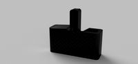
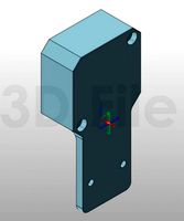
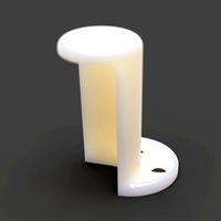
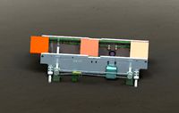
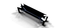
Update 2/28/18 - Please refer to the picture of the two parts in Slic3r that I have uploaded. This is the proper orientation for printing the parts so that there is no need for supports.
After a lot of design reviews and changes I've finally landed on a design that I think you will all like. It is simple and works like a charm. It is available to those using the stock idler (although I'd strongly advise an upgrade to a dual bearing unit), a gt2-16t idler (no more than 8.4mm wide) or a gt2-20t idler(no more than 8.4mm wide). When downloading the STL files, please be sure to select the proper file. They are all named according to the idler you wish to use. In addition to that, the 3D parts are embossed with "s" for stock idler, "16" for 16 tooth idler and of course "20" for 20 tooth idler. The Y axis adjuster arm is standard across the three choices.
This only requires some additional hardware which is listed below but requires no modifications to the printer itself. It can be used in conjunction with any motor mount solution that retains the stock motor mounting position and it must be used with any belt holder that retains the stock belt location dimensions (stock belt holder is more than sufficient).
When inspecting any misalignment issues on the 3D assembly of the Prusa i3 mk3 created by jzkmath, I found that there was .5mm misalignment between the motor pulley and the belt holder. I strongly believe that this very minor misalignment does not warrant printing a new belt holder or motor mount. Going forward with my design I wanted to be able to mate up with the stock belt holder while maintaing great alignment and parallelism between the belt and the carriage. This tensioner maintains perfect belt alignment throughout the entire adjustment travel since the pulley never moves vertically.
This has been tested on a Prusa i3 mk3 (thanks jweaver!) and fits beautifully with no interference issues, perfect belt parallelism (by eye) and gives the end user the ability to finely tune the tension on the belt. BINGO.
Hardware needed:
-M3x35mm socket head cap screws (2 pieces)
-M3x30mm socket head cap screws (1 piece)
-M3 Nylock nut (3 pieces)
-your choice of idler pulley
assembly instructions:
Place the Y axis adjuster arm over and onto the idler frame mount leaving the slot for the Nylock nut facing out. Using one M3x35mm socket head cap screw and one Nylock nut to secure the adjuster arm onto the idler frame mount at the pivot point. DO NOT overtighten this as the adjuster needs to be able to pivot.
Using your pulley of choice, place it into the idler frame mount mounting ears and align the idler bearing, mounting ear and slot on the side of the adjuster arm. Using one M3x35mm socket head cap screw, insert it all the way through the three items and use one M3 nylock nut. Again, DO NOT overtighten this as the adjuster needs to be able to pivot.
Insert one M3 Nylock nut into the adjuster arm slot and using one M3x30mm socket head cap screw, insert through the ear on the idler frame mount and into the adjuster arm catching the Nylock nut.
Install two Nylock nuts into the provided hex holes. At this point you are reusing the Nylock nuts that came with the printer.
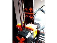
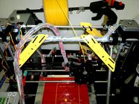
Install assembled belt tensioner with the pivot point towards the top. During belt tensioning it is important to refer to the manual as to the specific tension required. A simple adjustment of the M3x30mm screw will be all that is needed for tensioning.
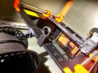
please refer to pictures for assembled tensioner.
Enjoy!
Update 3/10/18 - I used jzkmath model of the assembled prusa i3 mk3 with the r2 components and found that the tensioner still works with the r2 belt holder, maintaining a belt path that is still parallel to the bed.
Update 2/28/18 - Please refer to the picture of the two parts in Slic3r that I have uploaded. This is the proper orientation for printing the parts so that there is no need for supports.
After a lot of design reviews and changes I've finally landed on a design that I think you will all like. It is simple and works like a charm. It is available to those using the stock idler (although I'd strongly advise an upgrade to a dual bearing unit), a gt2-16t idler (no more than 8.4mm wide) or a gt2-20t idler(no more than 8.4mm wide). When downloading the STL files, please be sure to select the proper file. They are all named according to the idler you wish to use. In addition to that, the 3D parts are embossed with "s" for stock idler, "16" for 16 tooth idler and of course "20" for 20 tooth idler. The Y axis adjuster arm is standard across the three choices.
This only requires some additional hardware which is listed below but requires no modifications to the printer itself. It can be used in conjunction with any motor mount solution that retains the stock motor mounting position and it must be used with any belt holder that retains the stock belt location dimensions (stock belt holder is more than sufficient).
When inspecting any misalignment issues on the 3D assembly of the Prusa i3 mk3 created by jzkmath, I found that there was .5mm misalignment between the motor pulley and the belt holder. I strongly believe that this very minor misalignment does not warrant printing a new belt holder or motor mount. Going forward with my design I wanted to be able to mate up with the stock belt holder while maintaing great alignment and parallelism between the belt and the carriage. This tensioner maintains perfect belt alignment throughout the entire adjustment travel since the pulley never moves vertically.
This has been tested on a Prusa i3 mk3 (thanks jweaver!) and fits beautifully with no interference issues, perfect belt parallelism (by eye) and gives the end user the ability to finely tune the tension on the belt. BINGO.
Hardware needed:
-M3x35mm socket head cap screws (2 pieces)
-M3x30mm socket head cap screws (1 piece)
-M3 Nylock nut (3 pieces)
-your choice of idler pulley
assembly instructions:
Place the Y axis adjuster arm over and onto the idler frame mount leaving the slot for the Nylock nut facing out. Using one M3x35mm socket head cap screw and one Nylock nut to secure the adjuster arm onto the idler frame mount at the pivot point. DO NOT overtighten this as the adjuster needs to be able to pivot.
Using your pulley of choice, place it into the idler frame mount mounting ears and align the idler bearing, mounting ear and slot on the side of the adjuster arm. Using one M3x35mm socket head cap screw, insert it all the way through the three items and use one M3 nylock nut. Again, DO NOT overtighten this as the adjuster needs to be able to pivot.
Insert one M3 Nylock nut into the adjuster arm slot and using one M3x30mm socket head cap screw, insert through the ear on the idler frame mount and into the adjuster arm catching the Nylock nut.
Install two Nylock nuts into the provided hex holes. At this point you are reusing the Nylock nuts that came with the printer.
Install assembled belt tensioner with the pivot point towards the top. During belt tensioning it is important to refer to the manual as to the specific tension required. A simple adjustment of the M3x30mm screw will be all that is needed for tensioning.
please refer to pictures for assembled tensioner.
Enjoy!
Similar models
thingiverse
free

Y-belt holder and tensioner for MK3 and Bear MK2, MK2.5, and MK3 by zbrozek
...i added the sight-line to the stock mk3 flavor mount. new solidworks source is up. it's now the 2019 version. happy holidays!
thingiverse
free

Belt tensioner axis Y Prusa i3 by 3DWnico
...self-locking nut m5
4 m4 nuts
2 m4 screws
belt tensioner designed for prusa i3 hictop but extensible for all prusa i3 versions.
thingiverse
free

Prusa MK3 Bear 20T 5ID Gates Y idler + tensioner
... on the insertion depth: rely exclusively on the belt to verify the alignment.
again, with great thanks to gregsaun for his work.
thingiverse
free

MK3 Y-Axis Belt Tensioner by edsped
...hout support.
someone in a forum requested step files so i'm attaching those as well...
note: this is for a 20t idler only...
thingiverse
free

Belt Tensioner for Prusa Mk3 by Bogdanko
... so.
4- made for the stock idler.
print it with petg and if you have trouble with the tolerances adjust them on your main slicer.
thingiverse
free

Prusa X axis tension arm for GT2 pulley by Tyros87
...s belt, to mount the 20 teeth gt2 pulley
fit the pulley with a 5 mm screw and a locknut.
more photos to come.
17 mm spacing model
thingiverse
free

Prusa i3 mk3s Bear X-Carriage R4 with modified belt holder by TroyJoachim
... by using the affiliate links below
amazon link: 16t pulley
aliexpress: 16t pulley
amazon link: 16t idlers
aliexpress: 16t idlers
thingiverse
free

FolgerTech 2020 i3 Y Axis Belt Holder and Tensioner by JWag
...un out of adjustment.
then just tighten the belt to tension and re-adjust after making a few prints to ensure good belt tension.
thingiverse
free

MK3 x-end-idler and x-end-motor for MK2S and MK2.5 by tbergman8
... trapezoidal nuts etc.
the stronger mounts for the z trapezoidal nuts need different bolts than the mk2s/mk2.5. m3x18 are needed.
thingiverse
free

Prusa i3 MK1 Y-axis belt holder by parkis
...nt is not same on both sides. now belt is nicely in line with pulley and idler.
you need m4 nut and long m4 screw (at least 35mm)
Mattyvee
thingiverse
free

Reinforced 3 bolt Y axis motor mount for Prusa i3 mk3 by MattyVee
...remains the same. see the assembly drawing for screw locations.
thank you again to jweaver for testing as well as the pictures!!!
thingiverse
free

Custom Y Motor Mount for Mk 3 3030 Haribo by Olef
...motor mounting for rigidity. fits 3030 extrusion. (remixed from mattyvee#39;s reinforced 3 bolt y axis motor mount for prusa...
thingiverse
free

Reinforced 3 bolt Y axis motor mount for Prusa i3 mk3 with End Stop by massigrn
...mk3 with end stop by massigrn thingiverse just the mattyvee#39;s y-axis motor mount with the addition of an end...
thingiverse
free
Belt Tensioner for Prusa Mk3 by Bogdanko
...prusa i3 mk3 y axis adjustable belt tensioner by mattyvee 1- used all the same screws m3-30mm and m3...
thingiverse
free
MK3 Y-Axis Belt Tensioner by edsped
...y-axis belt tensioner by edsped thingiverse another take on mattyvee#39;s outstanding belt tensioner. in my case no mater what...
thingiverse
free

LDO Gates 16T Idler Frame for Prusa MK3 Y Axis Adjustable Belt Tensioner
...adjustable belt tensioner thingiverse this is a remix of mattyvee#39;s 16t idler base to accommodate a larger and more...
thingiverse
free

P3Steel Y-Axis Adjustable Belt Tensioner by akurz42
...tensioner by akurz42 thingiverse this is a remix of mattyvee#39;s brilliantly simple design. after having the tensioner in use...
thingiverse
free

Improved Prusa Mk3 Y belt holder - stock compatible
...the stock idler, or the y belt tensioner by mattyvee (https://www.thingiverse.com/thing:2786671 - which is great, but the tension made...
Mk3
turbosquid
$50
cention mk3
...ty free 3d model cention mk3 for download as ma, obj, and fbx on turbosquid: 3d models for games, architecture, videos. (1454148)
turbosquid
$129
MK3 Tank
... available on turbo squid, the world's leading provider of digital 3d models for visualization, films, television, and games.
turbosquid
$100
Toyota Supra MK3
... available on turbo squid, the world's leading provider of digital 3d models for visualization, films, television, and games.
turbosquid
$44
cention mk3 low poly
...d model cention mk3 low poly for download as ma, obj, and fbx on turbosquid: 3d models for games, architecture, videos. (1454666)
turbosquid
$30
Challenger I Mk3 Falcon
... available on turbo squid, the world's leading provider of digital 3d models for visualization, films, television, and games.
turbosquid
$10
American Frag hand grenade MK3
...free 3d model american frag hand grenade mk3 for download as on turbosquid: 3d models for games, architecture, videos. (1393624)
turbosquid
$20
Mk3 US Navy Combat Knife
...ty free 3d model mk3 us navy combat knife for download as fbx on turbosquid: 3d models for games, architecture, videos. (1172791)
3d_export
$29

Ford Fiesta MK3 Modified 3D Model
...7 tumerfx mtumer mehmet t?mer 1993 1995 1996 wrc special modifed modifiye
ford fiesta mk3 modified 3d model mtumer 30698 3dexport
3d_export
$99

Toyota Supra Mk3 19861993 3D Model
...ort fast coupe japan 1986 1987 1988 1989 1990 1991 1992 1993 tuning turbo
toyota supra mk3 19861993 3d model squir 62530 3dexport
turbosquid
$5
Timothy Oulton Mars Chair MK3
...on mars chair mk3 for download as 3ds, max, obj, fbx, and dae on turbosquid: 3d models for games, architecture, videos. (1209782)
Tensioner
3d_export
$5
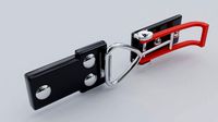
adjustable tension lock
...adjustable tension lock
3dexport
adjustable tension lock
turbosquid
$5
tension ring
...oyalty free 3d model tension ring for download as fbx and stl on turbosquid: 3d models for games, architecture, videos. (1553452)
turbosquid
$3

Tension Chair
...free 3d model tension chair for download as obj, c4d, and fbx on turbosquid: 3d models for games, architecture, videos. (1251503)
3d_export
$5
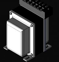
transformador de tension
...transformador de tension
3dexport
transformador de tension entrada 460vac salida 220vac marca audax
turbosquid
$20
Motorbike Chain Tensioner
...y free 3d model motorbike chain tensioner for download as stl on turbosquid: 3d models for games, architecture, videos. (1428322)
turbosquid
$25
TENSION-WOOD-CHAIR
... available on turbo squid, the world's leading provider of digital 3d models for visualization, films, television, and games.
turbosquid
$25

tension-bentwood-chair
... available on turbo squid, the world's leading provider of digital 3d models for visualization, films, television, and games.
turbosquid
$19
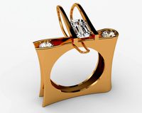
Tension engagement ring
...n engagement ring for download as obj, fbx, 3dm, dwg, and stl on turbosquid: 3d models for games, architecture, videos. (1491631)
3d_export
$10
Ruby Tension set Ring 3D Model
...ruby tension set ring 3d model
3dexport
tension set ruby ring in 18k
ruby tension set ring 3d model rehansheikh 25254 3dexport
turbosquid
$20
Superficial Tension Exp. Image.max
... available on turbo squid, the world's leading provider of digital 3d models for visualization, films, television, and games.
I3
3d_export
$10
suv i3
...suv i3
3dexport
suv i3 2013 series
3d_ocean
$89

BMW i3 2012
...y, in real units of measurement, qualitatively and maximally close to the original. model formats: - *.max (3ds max 2008 scanl...
cg_studio
$99

BMW i3 20143d model
...
cgstudio
.3ds .c4d .fbx .lwo .max .obj - bmw i3 2014 3d model, royalty free license available, instant download after purchase.
cg_studio
$99

BMW i3 20123d model
...tudio
.3ds .c4d .fbx .lwo .max .mb .obj - bmw i3 2012 3d model, royalty free license available, instant download after purchase.
cg_studio
$99

BMW i3 20143d model
...tudio
.3ds .c4d .fbx .lwo .max .mb .obj - bmw i3 2014 3d model, royalty free license available, instant download after purchase.
humster3d
$75

3D model of BMW i3 2014
...
buy a detailed 3d model of bmw i3 2014 in various file formats. all our 3d models were created maximally close to the original.
humster3d
$40

3D model of Kitchen Set I3
...uy a detailed 3d model of kitchen set i3 in various file formats. all our 3d models were created maximally close to the original.
3d_ocean
$30

Kitchen set i3
...ensils oven plates shelves sink table ware
kitchen set i3 include 3d models: cooker, oven, sink, cupboards, table, chair, plates.
3d_ocean
$89

BMW i3 2014
...y, in real units of measurement, qualitatively and maximally close to the original. model formats: - *.max (3ds max 2008 scanl...
cg_studio
$99

BMW i3 Concept 20113d model
...i3
.3ds .c4d .fbx .lwo .max .obj - bmw i3 concept 2011 3d model, royalty free license available, instant download after purchase.
Prusa
turbosquid
$2
Frame Filament Guide Clip-On for Prusa Mk3
...rame filament guide clip-on for prusa mk3 for download as stl on turbosquid: 3d models for games, architecture, videos. (1634730)
3d_export
free
prusa i3 mk3s laser mount for opt lasers
...to learn more about the blue laser technology that conceived the cutting and engraving laser heads from opt lasers, please visit:
turbosquid
free
Prusa small printer adapter holder
...er for download as ipt, skp, dwg, dxf, fbx, ige, obj, and stl on turbosquid: 3d models for games, architecture, videos. (1642936)
3d_export
$30

geisha by jonathan adler
...** i did a 3d printing test in the prusa software, you can find it among the attached images.<br>exchange:<br>.blend...
thingiverse
free

Prusa without Prusa (rc2) by madless
...prusa without prusa (rc2) by madless
thingiverse
just the main part of prusa rc2 faceshield, without writing.
enjoy :)
thingiverse
free
Prusa by acejbc
...prusa by acejbc
thingiverse
prusa knob info
m3 8mm screw
thingiverse
free
Prusa house
...prusa house
thingiverse
how prusa house could look like...
thingiverse
free

Prusa Mk2 "Fake Prusa" LCD cover by anraf1001
...r by anraf1001
thingiverse
version of prusa's lcd cover with "fake prusa" instead of "original prusa"
thingiverse
free
Prusa stabilizator by gutiueugen
...prusa stabilizator by gutiueugen
thingiverse
prusa stabilizator
thingiverse
free
Keychain Prusa by rbarbalho
...keychain prusa by rbarbalho
thingiverse
keychain with text prusa.
Belt
turbosquid
$9
Belt conveyor belt
...t conveyor belt for download as 3ds, ige, obj, stl, and sldas on turbosquid: 3d models for games, architecture, videos. (1226546)
3d_export
$6
belt
...d then comes off and fastens at the front of the seat. version: 2015 units: millimetres x-form: yes polys: 120 950 verts: 163 944
3d_export
$7
belt grinder
...belt grinder
3dexport
belt grinder
3d_export
$5
Belt conveyor
...belt conveyor
3dexport
belt conveyor
3ddd
$1
column belt
...column belt
3ddd
колонна
column belt
turbosquid
$5
Belt
... available on turbo squid, the world's leading provider of digital 3d models for visualization, films, television, and games.
3d_ocean
$5
Leather Belt
...ather belt is created in 3dsmax 2011 and rendered with vray 1.5 and it has all the texture included with the multiple obj format.
3d_ocean
$5
Belt Ring
...belt ring
3docean
belt jewelry ring
belt ring 3d model. total weight 3.5 gram & 1.1 stone size. 3dm and obj file format.
design_connected
$11
Belt Round
...belt round
designconnected
meridiani belt round computer generated 3d model. designed by parisio, andrea.
design_connected
$11
Belt Oval
...belt oval
designconnected
meridiani belt oval computer generated 3d model. designed by parisio, andrea.
Axis
3ddd
$1

Мария Axis
...
3ddd
кухня , классическая , axis
модель кухни.
3d_export
$22
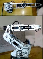
Axis robot 6-axis robotic arm
...ing parts drawings, standard parts purchased parts list, can be produced directly according to the drawings, welcome to download!
3ddd
free
Versatile Axis
...ddd
nexus , плитка
http://bvtileandstone.com/ceramic-porcelain/versatile-axis/
3d_export
$19
robot 2 axis
...robot 2 axis
3dexport
robot 2 axis
turbosquid
$40
Axis R5F
... available on turbo squid, the world's leading provider of digital 3d models for visualization, films, television, and games.
turbosquid
$40
Axis S5F
... available on turbo squid, the world's leading provider of digital 3d models for visualization, films, television, and games.
turbosquid
$30
Axis Athlon
... available on turbo squid, the world's leading provider of digital 3d models for visualization, films, television, and games.
turbosquid
$10

Linear Axis
... available on turbo squid, the world's leading provider of digital 3d models for visualization, films, television, and games.
3d_export
$15

drawing axis
...drawing axis
3dexport
simple rendering of the scene file
3ddd
$1

versatile axis ARC
...versatile axis arc
3ddd
versatile , плитка
versatile axis arc red dot design award
Adjustable
3d_ocean
$7
Adjustable Wrench
...adjustable wrench
3docean
adjustable wrench highly detailed wrench
highly detailed adjustable wrench.
3ddd
$1
Adjustable Stool
...adjustable stool
3ddd
табурет
wooden adjustable stool.
3d_ocean
$20

Adjustable Gym Bench
...st adjustable bench black equipement gym gymnastic indoor silver sport workout
3d model of black and silver adjustable gym bench.
3d_ocean
$20
Adjustable Gym Bench
...st adjustable bench black equipement gym gymnastic indoor silver sport workout
3d model of black and silver adjustable gym bench.
3d_ocean
$16

Adjustable Weight Bench
...arbell bench black equipement gym gymnastic indoor sport weight workout
3d model of black adjustable weight bench with a barbell.
turbosquid
$5

Adjustable wrench
...
royalty free 3d model adjustable wrench for download as fbx on turbosquid: 3d models for games, architecture, videos. (1313414)
3d_export
$5
adjustable tension lock
...adjustable tension lock
3dexport
adjustable tension lock
turbosquid
$1

Adjustable Wrench
...free 3d model adjustable wrench for download as obj and blend on turbosquid: 3d models for games, architecture, videos. (1446736)
turbosquid
$1

Adjustable Wrench
...y free 3d model adjustable wrench for download as c4d and fbx on turbosquid: 3d models for games, architecture, videos. (1379022)
3d_export
$5
Adjustable key
...adjustable key
3dexport
Y
turbosquid
$1

Tetera y Galletas y Caf
... available on turbo squid, the world's leading provider of digital 3d models for visualization, films, television, and games.
3ddd
$1

Смеситель Y-CON
...смеситель y-con
3ddd
смеситель , y-con
смеситель y-con
3ddd
$1
Y-Chair
...y-chair
3ddd
tom dixon
y-chair designed by tom dixon,
3ds max + obj, corona
3ddd
$1
Y Chair compilation
....net/products/us/y-chair-sled-base
y chair swivel basehttp://www.tomdixon.net/products/us/y-chair-swivel-base
turbosquid
$190
Y-8
...y-8
turbosquid
royalty free 3d model y-8 for download as max on turbosquid: 3d models for games, architecture, videos. (1658891)
turbosquid
$7
Bench Y
...turbosquid
royalty free 3d model bench y for download as obj on turbosquid: 3d models for games, architecture, videos. (1488746)
turbosquid
$15

bonePile Y
...oyalty free 3d model bonepile y for download as blend and obj on turbosquid: 3d models for games, architecture, videos. (1546374)
turbosquid
$7

Y for Yarn
...d
royalty free 3d model y for yarn model for download as max on turbosquid: 3d models for games, architecture, videos. (1699732)
turbosquid
$2
FONT Y
...quid
royalty free 3d model font y for download as ma and obj on turbosquid: 3d models for games, architecture, videos. (1549457)
3ddd
$1

WOOD-y
...wood-y
3ddd
wooden guy