Cults

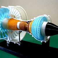
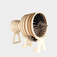
Propfan Engine, Pusher Type
by Cults
Last crawled date: 6 years, 2 months ago
"Propfan Engine", "Open Rotor Engine" and "Ultra High Bypass Engine" was developed as "Advanced Turboprop Engine" to get the high flying speed obtaining about the same fuel consumption as "Turboprop Engine.
There are several type of engines as follows;
"Puller (Retract) type" - Contra (Counter)-Rotating Propeller (Fan) with gearbox is located at front like as common turboprop.
"Pusher (Un-Ducted Fan) type” - Contra-Rotating Fan without gearbox is located at rear.
But the development of these type engine seems interrupted according to the noise problem, etc. except one company in France.
The contra-rotating power turbine mechanism with sweep-back angle fan blades of "Pusher Type" aroused my interest very much.
Then I tried to make a desktop model, but it was very difficult to get smooth contra-rotation.
But my target model was able to be eventually made as result of several trial and error.
A. Features of this model are;
1. Contra-Rotating Fan (PT: Power Turbine) can be turned by a home type vacuum cleaner.
2. Engine (Gas-Generator) cutaway model is inside of Cowling, but it is not rotated by the air.
3. Entire engine cowling with removable cover.
Video: https://youtu.be/2Hu1QvJ5J9o
B. Assembly Manual (PDF format, total 19 pages)
The detail assembly manual including "Parts-List", "After printing treatment" and "Assembly procedure" are prepared based on "Standard Skill (Filing, Drilling, Tapping and painting)".
The important adjustment of axial clearance is described in the manual as marked ●.
C. General Notes
1. Bearing Selection
Bearings are very important parts to get smooth rotation. This model is based on using with following size "Open type" ball bearings because of low friction.
ID x OD x W = ① 7 x13 x 3 ② 9x17x4 ③ 17x30x7 (2pcs)
[CAUTION]: "Shield type" ball bearing is thicker, then rubbing problem may occur.
2. For M1.4 Screw
No need “Tapping”. Drill with φ1.0 drill then direct screw-in.
3. STL file name
“ws” of last 2 digits means “With Support” special designed.
Download files includes;
-files: STL Files (48 items)
-PDF(Zip) File: Assembly Manual
-images: Assembly Photos
Purchase Parts Information;
-BRGs
See Assembly Manual
-Aluminum Tubes
See Assembly Manual
-Screws
Micro screws M1.4x3.5L - Appox. 30 ea - Direct screw-in to 1 mm dia hole (No nut)
Screws M2 x ** - See Assembly Manual
Assembly Points
- Standard Skill (such as Drilling, Tapping, Filing, Tightening, Painting and Gluing etc) is needed and perseverance too.
- Others: See Assembly Manual
Total Net Print Time: Approx. 80HR
- (Estimated as case of PLA, 0.4mm Nozzle, 0.2mm Layer Height, 40% infill and No raft and support)
Note: When at actual print, each parameter may be adjusted by your experience.
Similar models
cults
$16

Turboprop Engine, for Business Aircraft, Free Turbine Type, Cutaway
...m in the creations which i made before.
i do hope your success!!
[update] - 2018.3.14
photo of typical special support is added.
cults
$10

Turboprop Engine, for Business Aircraft, Cutaway
... hope your success!!
[update 2017.12.15]
for "dummy propeller assy", related stl files (4), photo and image are added.
cults
free

Rotational Stand for Turboprop Engine Cutaway
...to.
- wood screws: appropriate screws can be used.
assembly points
- stl parts position will be adjusted by the model you made.
cults
free

Turboprop Engine Modified Parts (No.2)
...as possible.
still this is not the model to print and assemble easily, i hope your perseverance too.
thank you for your interest.
cults
free

Turboprop Engine
...018.2.13
https://cults3d.com/en/3d-model/tool/turboprop-engine-modified-parts-no-3
before make this, please refer these. thanks.
cults
free

Jet Engine, Geared Turbofan (GTF)
...yer height, 40% infill and no raft and support)
note: when at actual print, each parameter should be adjusted by your experience.
cults
free

Turboprop Engine Modified Parts (No.3)
...ecommended.
still this is not the model to print and assemble easily, i hope your perseverance too.
thank you for your interest.
cults
$5

Jet Engine, Single-Spool with AfterBurner
...
price discount
[update 2017.12.14]
for "non-shrouded turbine blades rotor", stl file (3), photo and image are added.
cults
$5

Turbofan Engine, for Business Aircraft, Cutaway
...out 10 hours to print.
note: when at actual print, each parameter may be adjusted by your experience.
i do hope your success!!
cults
free

Turboprop Engine Modified Parts
...urbine rotor to shaft
this is not the model to print and assemble easily, i hope your perseverance.
thank you for your interest.
Bypass
cults
free
Jet Engine, 3-Spool
...for the latest jet engine for passenger planes, the bypass ratio is bigger and bigger to improve the engine-performance....
cults
free
Jet Engine, Geared Turbofan (GTF)
...for the latest jet engine for passenger planes, the bypass ratio is bigger and bigger to improve the engine-performance....
Sweep
cults
free

Z-15 Stealthy Tomcat
...is basically a naval version of the f-22 with variable-sweep wing. unfortunately, it remained as a concept. if you...
cults
free

Wheels for OpenRC F1 for F104 tires and differential
...the wheels in the openrc file set. i installed sweep tires on my wheels. the tires should be glued...
cults
free

Large & Small LED Lamps
...a simple hemisphere to a more complex polygonal rail sweep shape. the basis for this geometry came from a...
cults
free

Along the River During the Qingming Festival
...rather than the holiday's ceremonial aspects, such as tomb sweepng and prayers. successive scenes reveal the lifestyle of all...
cults
free

Sphere Surface Dissection, Baseball, Tennis Ball, Math
...sketch a 45-degree right triangle, and then perform a sweep cut along the whole path around the opening. now,...
cults
free

WARBOTRON/MACHINE BOY VORTEX to IDW ROTORSTORM kit
...schematics (waist rotated 180 degrees to allow for an up-sweep of tail) plus some fiddling with arms. take a...
Pusher
cults
free

Bunny Paste Pusher
... out of the tube. dont let your fingers do the hard work, just slide the paste pusher along the tube and let the good times roll.
cults
free

Cat Paste Pusher
...paste/ sunscreen. dont let your fingers do the hard work, just slide the paste pusher along the tube and let the good times roll.
cults
$1

Puppy Paste Pusher
...e just put this cute little puppy onto the end of your toothpaste tube and slide it up.
save money and time with this great tool.
cults
free

Power Pusher
...lade steady so it can move soil, rubble, sand, or even stubborn cookie crumbs out of the way.
this one was designed by makerbot.
cults
free

Small Pusher for Safe Cutting on your bandsaw, scroll saw, etc :)
...small pusher for safe cutting on your bandsaw scroll saw etc :)
small pusher for safe cutting on your bandsaw, scroll saw, etc :)
cults
free

Super simple paste pusher - Useful 3D prints: #1 Bathroom
...to subscribe, like and comment because it motivates me a lot. also don't forget to share my videos with friends!
#dagomerlin
cults
free

Harrope Cable Cam GoPro v1.0
...and tensioners to install the ropes. picker with rope pusher for the cable cam. how to install it? the...
Ultra
cults
$1

Goku Ultra Instinct
...goku ultra instinct
cults
dragon ball goku ultra instinct saiyan great
3d model of goku ultra instinct made on mudbox. (beginner)
cults
$6

Ultra modern
...ultra modern
cults
math modern pendant
6cm x 4.3cm x 2.5cm
volume: 0.34ml
weight 18k: 5.6gr
cults
$1

ultra-sound humidifier reducer
...ultrasound
ultra-sound humidifier reducer
qm3d
customized parts on www.qm3d.fr.nf
qm3dcontact@gmail.com
06 33 41 81 60
cults
free

Future Bear - M5A1 Ultra Evolution
...future bear - m5a1 ultra evolution
cults
m5a1 tank toys
my 123d design portfolio: future bear - m5a1 ultra evolution
cults
$3

ULTRA MAGNUS RID MISSIL REPLACEMENT
...placement
cults
transformers replacement toy ultra magnus rid collection
if you lost parts of your collection, you will love it.
cults
$9

Ultra modern two-finger strap
...ern two-finger strap
cults
signet ring modern man money steel ultra
diam: 20mm x 2
49mm x 15mm x 24mm
vol: 4.54ml
poids 925: 47gr
cults
free

Ultra Sierra Nevada Running mountain
...in montana education geography home maps map 3d map decoration running
ultra 3d sierra nevada circuit
i remember running trophy
cults
free

21mm Lens Cap (for H9 Ultra HD 4K Action Camera)
... me doing more things. thanks!
banggood: https://goo.gl/zxgx3a
gearbest: https://goo.gl/ffe59f
aliexpress: https://goo.gl/bqli15
cults
free

Ultra Durable Pagoda Antenna Protector
... of the pagoda antenna as the others have different plate spacing.
don't own a 3d printer? no problem! purchase it on ebay.
cults
$19

Mk Ultra - 3D printable 1/10 4wd buggy
...untersunk.
-6x m3x25 countersunk.
nuts:
-15x m3 nyloc.
-4x m4 nyloc
new option parts will appear as new free items on cults3d.
Rotor
cults
free

Motorcycle Rotor Brake Disk Cover
...motorcycle rotor brake disk cover
cults
motorcycle rotor brake disk cover
motorcycle rotor brake disk cover
cults
free

Rotor 3-phase electric generator.
...rotor 3-phase electric generator.
cults
rotor 3-phase electric generator.
rotor 3-phase electric generator.
cults
free

Rotor Riot Coaster
...r
cults
quadcopter rotorriot
just a simple rotor riot coaster with the exposed infill
bottom layer = 3
shell = 3
top layer = 0**
cults
$1
![[Raptor 50] Retaining the tail of the tail rotor](/t/2992698.jpg)
[Raptor 50] Retaining the tail of the tail rotor
... tiger
parts to hold the tail of the raptor 50 in place to prevent the tail strap from loosening or the tail rotor from rotating.
cults
free

Jet Engine, Rotable 2 Spool Rotors
... model.
this "remix" can be helpful to explain about the total jet engine function easely, i hope.
thanks for viewing!
cults
$12

Compressed air motor
...air motor cults engine the engine which actually work. rotor ...
cults
free
Turboprop Engine Modified Parts
...clearance red-prop-shaft201: reduced axitial interference turbine- case101b: increased hp rotor clearance and convenience for assembly, the following tools are...
cults
free

Flying Helicopter Toy
...flying toys - pull this helicopter;s tail and its rotor will fly high in the...
cults
free

Flying Helicopter Toy - H145
...hear it click when it is engaged. the main rotor is the same as 3dbrooklyn's model, so feel free...
cults
$1

Conversion kit for making a flyable Revell 1:32 Westland Lynx kit.
...(or petg for motor heat resistance) micromaintotor02.stl - main rotor pitch link rotation guide. tailrotor02.stl - tail rotor and...
Turbine
cults
free

Turbine
...turbine
cults
turbine elisse turbo
turbine turbo.
cults
free

Miniature spining turbine
...miniature spining turbine
cults
miniature spining turbine
miniature spining turbine
cults
free

AXIAL TURBINE WHEEL
...axial turbine wheel
cults
axial turbine wheel
axial turbine wheel
cults
free

Ugrinsky wind turbine.
...ugrinsky wind turbine.
cults
ugrinsky wind turbine.
ugrinsky wind turbine.
cults
free

Heart turbine - Heart turbine
...
a new little heart, blowing on it, it will turn quickly.
1 hour 30 minutes of printing.
gadget, key holder or pendant.
a +
nop21
cults
free

TURBINE LAMP
...turbine lamp
cults
turbine lamp
lamp to be printed by fdm. needs 4 bolts m3, with a minimum 10 mm length.
cults
free

Vertical Axis Turbine
...ius energy wind river
this is a vertical axis turbine that can be used to generate energy with small water currents or even wind.
cults
$7

Iphone 7 case - Turbine
...iphone 7 case - turbine
cults
iphone 7 case turbine car wheel tread pattern
iphone 7 case - car turbine and wheel tread pattern.
cults
free

Wind turbine powerbank
...make your wind turbine powerbank and all the informations about the wind turbines in general, purpose, and ideas to play with it.
cults
free

Mini Desalination Steam Turbine
...hare your creation.
read more on ge reports: http://www.gereports.com/honey-i-shrunk-the-steam-turbine-and-it-makes-clean-water/
Jet
cults
$1

Futuristic Jet
...futuristic jet
cults
a sculpted futuristic jet toy for kids
cults
free

Perfect water jet
...perfect water jet
cults
perfect water jet
perfect water jet
cults
free

Little Jet Plane
...little jet plane
cults
little jet plane
little jet plane
cults
free

Water Jet drive
...water jet drive
cults
water jet drive
water jet drive
cults
$2

Jet Cat ECU
...jet cat ecu
cults
halterung für jet cat tcu
cults
free

Simple water jet drive.
...simple water jet drive.
cults
simple water jet drive.
simple water jet drive.
cults
free

JetRo water jet robot
...jetro water jet robot
cults
jetro water jet robot
jetro water jet robot
cults
$12

Jet Plane
...f you intend to buy the models, please leave feedback in the comments and rate me.
if you have questions you can write me message
cults
$6

Fighter jet
...fighter jet
cults
toy
bonjours this creation is a french fighter plane
cults
free

Jet
... download this 3d printer file and make it with 3d printing. let’s enjoy!
this 3d model was originally shared on poly by google.
Engine
cults
free

Metronome Engine
...metronome engine
cults
metronome engine
metronome engine
cults
free

Engine block
...engine block
cults
engine car motor
monoblock
cults
free
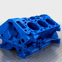
V6 engine block
...v6 engine block
cults
engine v6
cylinder block engine v6
cults
free

Xaar: Zyntari Engineer
...xaar: zyntari engineer
cults
xaar: zyntari engineer
xaar: zyntari engineer
cults
free

Working Train Engine "Kevin's Engine"
...p;quot;
cults
working train engine "kevin's engine"
working train engine "kevin's engine"
cults
free

Train Engine
...train engine
cults
model railroad constructor part number 1 train engine
model railroad. constructor. part number 1
cults
free
Jet Engine
...n assembling. remember: glue and patience go a long way!
all pieces print without support.
this model was designed by makerbot.
cults
free

Perendev engine
...perendev engine
cults
stl, solidworks, rar, ...
cults
free

RC model engine
...rc model engine
cults
this is a mockup of an enya rc model engine.
cults
free

STAR SERVO-ENGINE
...star servo-engine
cults
accessory
star for servo-engine with interior of 10 mm with thread and grip
Fan
cults
free

fan
...fan
cults
fan
fan
cults
free

Fan
...fan
cults
fan
fan
cults
free

Fan
...fan
cults
fan
fan
cults
$6

Fan
...med weapon blades video games
fan is a weapon inspired by a famous video game.
fan is a weapon inspired by a famous video games.
cults
free

Fan for repairing a 40x10mm computer fan.
...n for repairing a 40x10mm computer fan.
cults
fan for repairing a 40x10mm computer fan.
fan for repairing a 40x10mm computer fan.
cults
free

Fan for summer
...fan for summer
cults
fan summer for
fan for summer
cults
$10

Min fan
...min fan
cults
wind turbine fan mini fan
small fan that can be used for wind or other projects
cults
free

Fan support
...fan support
cults
prusa i3
x-axis fan support prusa i3
fan size 40 × 40
cults
free

Ball Fan
... fan’, and 11+’s usb-powered ‘o-fan’.
http://www.infmetry.com/products/u-like-usb-desktop-fan
http://elevenpl.us/product/o-fan/
cults
$2

50mm Fan Cover
...ter computer fan case fan grill grille classic
a classic yet unique fan cover for a 50mm fan brought to you by twisted tiger labs
Power
cults
$1

Power Earrings
...power earrings
cults
earrings power
design in catia v5
cults
$2

Power transmission
...raight teeth and 16 conical teeth.
a central opening of 12 mm and a final dimension of 31.6 mm of maximum width x 21 mm of height
cults
free

Power Pylon (15mm scale)
...power pylon (15mm scale)
cults
power pylon (15mm scale)
power pylon (15mm scale)
cults
free

WOW Orc man with power
...wow orc man with power
cults
wow orc man with power
wow orc man with power
cults
free

GnomIoT - The Solar Powered Garden Sensor
...omiot - the solar powered garden sensor
cults
gnomiot - the solar powered garden sensor
gnomiot - the solar powered garden sensor
cults
free

ArGenArc -Electric Power generator on Archimedes paradox.
...aradox.
cults
argenarc -electric power generator on archimedes paradox.
argenarc -electric power generator on archimedes paradox.
cults
free

CEE 7 AC Power Socket
...cee 7 ac power socket
cults
a 3d model of a cee 7 european-style ac power socket.
cults
free

iPhone Power Socket Shelf
...ow you can put your smartphone on it and charge!
feel free to customize it here: https://www.vectary.com/u/meshtush/power-socket
cults
free

USB Power Bank
...power bank
cults
apple backup_battery ipad iphone phone_charger powerbank usb usb_charger minty_boost
approximate project cost:
cults
free
Power Pusher
...lade steady so it can move soil, rubble, sand, or even stubborn cookie crumbs out of the way.
this one was designed by makerbot.
Type
cults
free

dogu -goggle-eyed type-
...dogu -goggle-eyed type-
cults
dogu -goggle-eyed type-
dogu -goggle-eyed type-
cults
free

86Duino Illusion Type 1
...86duino illusion type 1
cults
86duino illusion type 1
86duino illusion type 1
cults
$5

Japanese Desserts - no hole (6 types)
...japanese desserts - no hole (6 types)
cults
japanese desserts - no hole (6 types)
japanese desserts - no hole (6 types)
cults
free

Type A Machines Blower Fan Shroud
...type a machines blower fan shroud
cults
fan type a machines blower shroud
type a machines blower fan shroud
cults
free

U-boat Type II keychain
...u-boat type ii keychain
cults
u-boat type ii keychain
u-boat type ii keychain
cults
$8

Turkish build type
...turkish build type
cults
turkish build building house
typical turkish build. special drawing.
cults
$1

Computer screen type A
...r square bell ding dong loading fence concrete deposit sncf 5 calvary jesus religion christian pc computer
computer screen type a
cults
free

Old Type French Wrench
...old type french wrench
cults
printed on zortrax m200 3d printer.
cults
$1

Lego duplo - Round tunnel type part
...go duplo - round tunnel type part
cults
toy lego duplo art
lego duplo for children type tunnel rounded
dimension: 61x31x42mm
cults
$4

support tete imprimante 3d type prussa i3
...support tete imprimante 3d type prussa i3
cults
support renforce pour tête d'imprimante 3d type prusa i3
Back
cults
free

Back
...back
cults
hyundai atos clip fixation hinge beach back tablet chest
fixing clip for the rear deck of a hyundai atos.
cults
free

look back cat
...look back cat
cults
look back cat
look back cat
cults
free

Picture Frame Back
...picture frame back
cults
picture frame back part 2
picture frame (part 2)
cults
free

Bus pull-back car toy
...bus pull-back car toy
cults
bus car_toy pull-back car toys
my 123d design portfolio - bus pull-back toy
cults
free

Skull Vw Back Logo
...skull vw back logo
cults
volkswagen passat 2006 skull car logo stl styling
skull vw logo for the back of the car
cults
$2

License plate of the machine Back to the Future
...oc out of time plate california
quality replica of the delorean plate back to the future. in the file there is also the key ring.
cults
free

Sports Car pull-back car toy
...sports car pull-back car toy
cults
car_toyn pull-back car sports_car toys
my 123d design portfolio - sports car pull-back toy
cults
free

Pokémon - Bulbasaur pull back car toy
...back car toy
cults
bulbasaur car_toy pokemon pokemon_go pull-back car toys
my 123d design portfolio - bulbasaur pull back car toy
cults
free

Pokémon - Pikachu pull back car toy
...ull back car toy
cults
car_toy pikachu pokemon pokemon_go pull-back car toys
my 123d design portfolio - pikachu pull-back car toy
cults
free

Pokémon - Charmander pull-back car toy
..._toy charmander pokemon pokemon_figures pokemon_go pull-back car toy toys
my 123d design portfolio - charmander pull-back car toy
Open
cults
$5

Bottle opener Bottle opener
...bottle opener bottle opener
cults
decapsuleur design
bottle opener
cults
free

Bottle Opener
...bottle opener
cults
bottle opener keychain
download this bottle opener keychain and be ready to celebrate!
cults
$1

Bottle Opener
... opener
cults
bottle opener beer parry friends tool basic
a basic bottle opener, you can personalise, to your parry with friends.
cults
$2

Open Closed
...open closed
cults
open closed
c'est ouvert? ou bien c'est fermé? le loquet rouge coulisse entre open ou closed au choix.
cults
free

Letter opener
...letter opener
cults
tool letter wife chest
letter opener with a woman's bust for the # lifehack3d contest
cults
free

Sword - Letter Opener
...sword - letter opener
cults
sword - letter opener
sword - letter opener
cults
free

Toy Rocket (Openable)
...toy rocket (openable)
cults
toy rocket (openable)
toy rocket (openable)
cults
free

Sphere Bottle Opener
...sphere bottle opener
cults
sphere bottle opener
sphere bottle opener
cults
$1

Bottle opener - Domo
...bottle opener - domo
cults
beer bottle opener cap drink
bottle opener - domo
cults
free

Moustache opener
...moustache opener
cults
author: florian bailly
High
cults
free

High Temple
...high temple
cults
high temple
high temple
cults
free

high resolution Whale
...high resolution whale
cults
whale high resolution
high resolution whale
cults
$4

monster high skull
...monster high skull
cults
monster high skull model and printed just for fun
cults
free

polarbear high resolution
...polarbear high resolution
cults
animals polarbear toy
sleepy polarbear high resolution 3d printed!
cults
free

High resolution tyrannosaurus
...high resolution tyrannosaurus
cults
dinosaur t-rex trex
high resolution tyrannosaurus 3d printable
cults
free

Ammonite High Heel Shoe
...ammonite high heel shoe
cults
ammonite high heel shoe
ammonite high heel shoe
cults
free

Horse High Heel Shoe
...horse high heel shoe
cults
horse high heel shoe
horse high heel shoe
cults
free

Squirrel High Heel Shoe
...squirrel high heel shoe
cults
squirrel high heel shoe
squirrel high heel shoe
cults
free

Lion High Heel Shoe
...lion high heel shoe
cults
lion high heel shoe
lion high heel shoe
cults
free

Monsters high skull pendant
...monsters high skull pendant
cults
monsters high skull pendant
monsters high skull pendant