Thingiverse
ProperWinder - Filawinder kit upgrade by universaljoint
by Thingiverse
Last crawled date: 3 years, 4 months ago
When I put together the laser cut acrylic filawinder kit that I bought in early 2020, I thought two things.
This is very flimsy and frustrating to use, but the concept is pretty sound.
We can rebuild him, we have the technology.
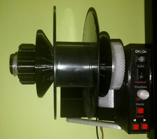
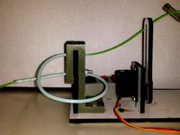
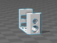
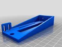
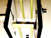
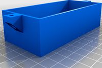
This is a complete frame replacement for that kit. The motor, control panel components, threaded rods and nuts, control board, and magnet are all reused.
Additional components needed are as follows:
A 5.5mm x 2.1mm DC Power Extension Cable (Right Angle Male to Female adapter) or equivalent. This is necessary as there is not enough space to plug the original adapter into the board when mounted inside this unit. The one I used was 10" long.
2pc M3X6 set / grub screw
5pc M3X3 machine screws
1pc M3X8
15pc M3X10
1pc M3X15
1pc M3X30
25pc M3X3mm X 4.2mm OD threaded heat-set inserts
2pc PC4-M10 passthrough pneumatic connectors (to secure PTFE coil)
Key Features:
Internally mounted motor
No tools needed to mount or remove spools
Sturdier construction allows elimination of secondary support arm
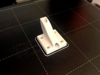
Multiple hanging options (the original design had a distinct lack of mounting holes)
Compact design optimized for printing without supports / large nozzle sizes.
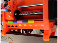
optional faceplate with color coded labels (MMU / multi extruder ready)
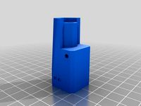
PTFE coil (to straighten the hot filament) from original design is now its own component to allow for a more optimized filament path, also includes depth adjustment. Makes use of PC4-M10 passthrough fittings to ensure that the PTFE tubing is held more securely.
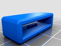
Please note that the wiring access cover STL provided is a blank. I am not using it at all currently, but added it too in case anyone would like to source proper panel mounted connectors and modify this cover for that purpose.
Intended for use with Filawinder improved wall mounted sensor
With gratitude to Greg Gaub for helping to test and improve this design.
Please note that some components are designed with sacrificial membranes over round holes in order to eliminate the need for supports. These should be cut away before assembly.
Important note: The connector for the potentiometer knob should be mounted upside down when attached to the control board (vs the original assembly instructions). If you don't do this, the servo arm will move in the opposite direction you expect when you calibrate it (this may be fixed in a future firmware modification, but for simplicity's sake flipping the connector does work)
Assembly steps for winder
Fix heat set inserts into holes for the board standoffs and cover mounts on the lower chassis.
Fix heat set inserts into the holes for the joint between the upper and lower chassis. These should be installed on the non-wall facing side of the chassis to make them harder to pull through.
Mount the servo to the upper chassis with the servo horn on the outside edge. Thread the servo wires through the provided channel so that they can reach the control box.
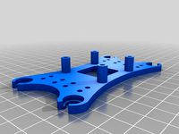
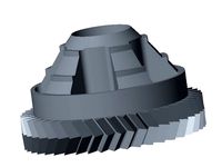
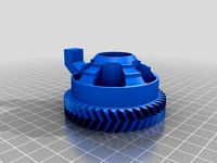
Mount the winder motor in the motor tray and secure in place with m3 screws. Mount the drive gear onto the motor shaft and secure in place with M3 grub screws. Mount the double gear with the M3X30 machine screw and heat set insert.
Slide the motor tray into the lower chassis, taking care not to pinch the motor wires. Fish the motor wires into the control box. Secure the the motor tray to the chassis with M3 screws.
Run the ribbon cable for the laser sensor from the control box through the channel with the motor wires and out the other side. Do the same with the 90 degree power cable extension.
Attach the upper chassis to the lower chassis from the back with M3 X 10 and M3X15 screws. There should be 2 wires hanging out of the access slot at the bottom - the ribbon cable for the laser sensor, and the female end of the power extension cable.
Attach faceplate, then mount toggle switches, potentiometer. The wires can be shortened or bundled up - there is enough space for the original length to be used. Take care to observe that the orientation of the toggle switches (especially the mode switch) corresponds to the printed labels.
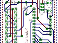
Connect cables to control board, then mount control board to the standoffs in the control box. The board is to be mounted with the microcontroller facing inward and the hall effect sensor facing the axle shaft. Secure the control board cover with M3 screws. Make sure the screw heads are flush with the cover so that the magnet holder can clear them when it is installed.
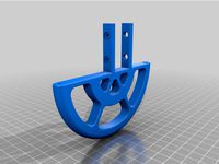
Mount the axle bearings inside the holes in each end of the main axle.
Insert magnet into the magnet holder, following polarity instructions per filastruder assembly manual. The magnet should be secured in a position as close to the tip of the holder as possible.
Thread the magnet holder into the mounting hole on the main axle gear. The height of the magnet should be adjusted so that it comes as close to the hall effect sensor as possible.
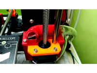
Assembling the axle is slightly challenging if you do it in the wrong order. First, mesh the teeth of the main axle gear with the double gear, and push the metal threaded rod through the hole in the lower chassis and all the way through the main axle. Secure at both ends with washers and nuts from the filastruder kit.
There are printable plugs included to dress the holes at each end of the axle.
Attach the servo arm to the servo horn.
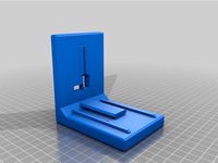
Assemble the two halves of the PTFE carrier by sliding them together. The holes in the top section are designed for PC4-M10 passthrough connectors. The preferred distance from the wall can be locked in place with a M3 screw in the holes on the bottom of the lower portion of this unit.
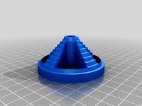
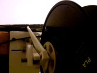
To mount a spool, thread a conical spool holder onto the shaft with the narrow end facing the spool. Then slide the spool over a shaft, followed by another spool holder with the narrow end also facing the spool. Tighten the second spool holder until it grips the spool. Next, lock the spool holder onto the shaft by threading the locknut STL onto the shaft and tightening it until everything is secure.
This is very flimsy and frustrating to use, but the concept is pretty sound.
We can rebuild him, we have the technology.
This is a complete frame replacement for that kit. The motor, control panel components, threaded rods and nuts, control board, and magnet are all reused.
Additional components needed are as follows:
A 5.5mm x 2.1mm DC Power Extension Cable (Right Angle Male to Female adapter) or equivalent. This is necessary as there is not enough space to plug the original adapter into the board when mounted inside this unit. The one I used was 10" long.
2pc M3X6 set / grub screw
5pc M3X3 machine screws
1pc M3X8
15pc M3X10
1pc M3X15
1pc M3X30
25pc M3X3mm X 4.2mm OD threaded heat-set inserts
2pc PC4-M10 passthrough pneumatic connectors (to secure PTFE coil)
Key Features:
Internally mounted motor
No tools needed to mount or remove spools
Sturdier construction allows elimination of secondary support arm
Multiple hanging options (the original design had a distinct lack of mounting holes)
Compact design optimized for printing without supports / large nozzle sizes.
optional faceplate with color coded labels (MMU / multi extruder ready)
PTFE coil (to straighten the hot filament) from original design is now its own component to allow for a more optimized filament path, also includes depth adjustment. Makes use of PC4-M10 passthrough fittings to ensure that the PTFE tubing is held more securely.
Please note that the wiring access cover STL provided is a blank. I am not using it at all currently, but added it too in case anyone would like to source proper panel mounted connectors and modify this cover for that purpose.
Intended for use with Filawinder improved wall mounted sensor
With gratitude to Greg Gaub for helping to test and improve this design.
Please note that some components are designed with sacrificial membranes over round holes in order to eliminate the need for supports. These should be cut away before assembly.
Important note: The connector for the potentiometer knob should be mounted upside down when attached to the control board (vs the original assembly instructions). If you don't do this, the servo arm will move in the opposite direction you expect when you calibrate it (this may be fixed in a future firmware modification, but for simplicity's sake flipping the connector does work)
Assembly steps for winder
Fix heat set inserts into holes for the board standoffs and cover mounts on the lower chassis.
Fix heat set inserts into the holes for the joint between the upper and lower chassis. These should be installed on the non-wall facing side of the chassis to make them harder to pull through.
Mount the servo to the upper chassis with the servo horn on the outside edge. Thread the servo wires through the provided channel so that they can reach the control box.
Mount the winder motor in the motor tray and secure in place with m3 screws. Mount the drive gear onto the motor shaft and secure in place with M3 grub screws. Mount the double gear with the M3X30 machine screw and heat set insert.
Slide the motor tray into the lower chassis, taking care not to pinch the motor wires. Fish the motor wires into the control box. Secure the the motor tray to the chassis with M3 screws.
Run the ribbon cable for the laser sensor from the control box through the channel with the motor wires and out the other side. Do the same with the 90 degree power cable extension.
Attach the upper chassis to the lower chassis from the back with M3 X 10 and M3X15 screws. There should be 2 wires hanging out of the access slot at the bottom - the ribbon cable for the laser sensor, and the female end of the power extension cable.
Attach faceplate, then mount toggle switches, potentiometer. The wires can be shortened or bundled up - there is enough space for the original length to be used. Take care to observe that the orientation of the toggle switches (especially the mode switch) corresponds to the printed labels.
Connect cables to control board, then mount control board to the standoffs in the control box. The board is to be mounted with the microcontroller facing inward and the hall effect sensor facing the axle shaft. Secure the control board cover with M3 screws. Make sure the screw heads are flush with the cover so that the magnet holder can clear them when it is installed.
Mount the axle bearings inside the holes in each end of the main axle.
Insert magnet into the magnet holder, following polarity instructions per filastruder assembly manual. The magnet should be secured in a position as close to the tip of the holder as possible.
Thread the magnet holder into the mounting hole on the main axle gear. The height of the magnet should be adjusted so that it comes as close to the hall effect sensor as possible.
Assembling the axle is slightly challenging if you do it in the wrong order. First, mesh the teeth of the main axle gear with the double gear, and push the metal threaded rod through the hole in the lower chassis and all the way through the main axle. Secure at both ends with washers and nuts from the filastruder kit.
There are printable plugs included to dress the holes at each end of the axle.
Attach the servo arm to the servo horn.
Assemble the two halves of the PTFE carrier by sliding them together. The holes in the top section are designed for PC4-M10 passthrough connectors. The preferred distance from the wall can be locked in place with a M3 screw in the holes on the bottom of the lower portion of this unit.
To mount a spool, thread a conical spool holder onto the shaft with the narrow end facing the spool. Then slide the spool over a shaft, followed by another spool holder with the narrow end also facing the spool. Tighten the second spool holder until it grips the spool. Next, lock the spool holder onto the shaft by threading the locknut STL onto the shaft and tightening it until everything is secure.
Similar models
thingiverse
free
Filawinder improved wall mounted sensor
...nt it from coming apart accidentally.
to reduce friction, 4mm od ptfe guides can be screwed and/or glued into the vertical vanes.
thingiverse
free
Mini Talon Vibration Isolated Control Board Mount by Ycopter
...ard with m3 bolts and mount cradle with standard rubber grommets. holes spaced to allow securing of wires with 2.5mm cable ties.
thingiverse
free
Artillery Sidewinder X1 spool holder replacement without filament runout sensor by Chair-No-Bill
...filament runout sensor. a common 4mm ptfe tube should fit in. you need two m3*16 screws and two m3 t-nuts for the front mounting.
3dwarehouse
free
Universal Aluminum Mounting Hub for 5mm Shaft, M3 Holes
... and one 1.5 mm allen wrench for use with the set screws. each hub has four threaded mounting holes for m3 screws (not included).
thingiverse
free
Filawinder PTFE stopper by Labieno
..., if the produced filament is too twisted and curled, you risk to
damage the motor, but if not, you'll surely save the servo.
grabcad
free

Arduino Uno / Mega Board Holders
...mega and uno. both have holes that can take m3 screws to secure the board with 2 mounting holes to secure the holders themselves.
thingiverse
free
Cable holder by DesignedByPepijn
...ogress, but should work fine
the passthrough holes are 10 mm in diameter, and the screw holes are designed for m3,5 metric screws
thingiverse
free
775 DC Motor Mount for DIY Dremel CNC
...nto the lower side of the holder. you need two halves of the shoe. use 4 10mm neodymium magnets to secure the dust shoe in place.
grabcad
free

RoboClaw Motor driver board mount
...law or roboclaw motor driver board 2 x 30amp
use m3 x 6mm screws in corners
slots in end are to secure cables with small zip ties
thingiverse
free
Micro servo SG90 holder by IronPitto
... the cables are supposed to go through the lower rectangular hole; i used two m3 10mm screws to connect the holder and the servo.

Universaljoint
thingiverse
free

Orange Shirt Day Pin by universaljoint
...al schools in canada. for an official backgrounder on this tradition (and official merch) visit http://www.orangeshirtday.org/
thingiverse
free
Fitbit Charge HR replacement strap retainer loop by universaljoint
...a fitbit charge hr, modeled using measurements from original part. metal clasp must be removed temporarily to install this part.
thingiverse
free
LACK enclosure MMU retrofit and ventilation parts by universaljoint
... lack enclosure, as well as some parts for a diy ventilation system based on a salvaged 90mm 12v fan from an old pc power supply.
thingiverse
free
Cold pull multiplexer for Prusa Multimaterial upgrade / MMU by universaljoint
...aning filament. the single hole at the top has a slight taper, which should allow a friction fit with a bowden tube if desired.
thingiverse
free

Pickle Rick multimaterial split for easier printing by universaljoint
...he face with a quad material printer. the bottom section is a single color print.
thank you to mosaic for this excellent model!
thingiverse
free
Prusa Multimaterial upgrade heatsink PTFE cutting jig - 41mm by universaljoint
...hat the inside diameter of this tubing is specified as 1.85-1.9mm, which is not the same as you will find on generic ptfe tubing.
thingiverse
free
Original Prusa i3 MK2/MK2S/MMU pinda probe cooler by universaljoint
...16" od vinyl tubing commonly sold by the foot at most hardware stores
wire
power supply for fan
m3x10mm machine screws (x8)
thingiverse
free
MMU2 Underslung Control Panel + Color-Code-Clip
...space for the color-code-clips to the nice model from universaljoint and i created another mmu2 frame holder with a...
thingiverse
free
Under-spool tabletop PTFE guide
...od ptfe tubing, so did my own inspired by universaljoint#39; design. also added one for 4mm. holes are for...
Filawinder
thingiverse
free
FilaWinder Flexible by hinge
...added more flexibility to the filawinder project made by ian j.. who is to credit for the hard work making it in the first place.
thingiverse
free
Filawinder spool holders and gear by tonycstech
...filawinder spool holders and gear by tonycstech
thingiverse
i use those to hold spools attached to the filawinder.
thingiverse
free
FilaWinder DIY friendly electronics by bernabap
... friendly electronics by bernabap
thingiverse
this is a diy friendly version of ianjohnson's electronics for the filawinder.
thingiverse
free
Filawinder Filament Thickness Gauge
...erse
base on the filabot filament gauge i designed this one for the filawinder it works great for me i hope you like it as well.
thingiverse
free
Filawinder Laser Filament Holder by Labieno
...hingiverse
this accessory substitutes the ptfe tube to keep the filament inside the laser range of the filawinder sensor holder.
thingiverse
free
Filawinder Gear by Niners11
...spool farther out away from the control board.
haven't printed yet, but bearing may not fit based on your printers settings.
thingiverse
free

Filawinder extra support for motor arm
... motor arm. the new housing is brittle acrylic. this can help support the motor arm if you break the base. see my youtube video.
thingiverse
free
Filawinder Nut Locker by lboucher
... this nut holder just prevents the nut from backing off. this design is quicker than putting on a locknut. simple and works well.
thingiverse
free
Filawinder spool hook by Sungod3k
...to it.
also check that the arm doesn't rip of components from the board the spacing of the motor and cogs could be different.
thingiverse
free
Filawinder Control Box - No Support by Fythios
... uses 45 degree over hangs and a couterbore m3 cutout. please use a hobby knife to cut up the thin layer of filler over the hole.
Upgrade
turbosquid
$15

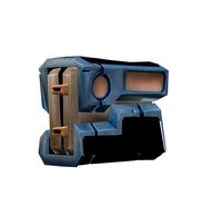
Upgraded Glock
...e 3d model upgraded glock for download as obj, fbx, and blend on turbosquid: 3d models for games, architecture, videos. (1185950)
3ddd
$1

Calligaris / UPGRADE
...calligaris / upgrade
3ddd
calligaris
c материалом
3d_export
free

cz upgrade
...cz upgrade
3dexport
https://www.buymeacoffee.com/mestrezen3d https://linktr.ee/mestrezen3
turbosquid
$80

Custer Tank upgrade
... available on turbo squid, the world's leading provider of digital 3d models for visualization, films, television, and games.
turbosquid
$39

Domestos 1 upgrade
... available on turbo squid, the world's leading provider of digital 3d models for visualization, films, television, and games.
3d_export
$10

Upgraded tea cup
...upgraded tea cup
3dexport
a cup with an unusual design and a unique shape for a more enjoyable tea experience
3d_export
$8

dixy outlander classic style upgraded poplar wood lounge chair
...utlander classic style upgraded poplar wood lounge chair
3dexport
dixy outlander classic style upgraded poplar wood lounge chair
turbosquid
free

AK-12 + Upgrades low-poly 3D model
...ow-poly 3d model for download as fbx, blend, and unitypackage on turbosquid: 3d models for games, architecture, videos. (1501145)
evermotion
$700

Upgrade from V-ray 1.5 to 3.5 for 3ds max
...here is no need to purchase a new dongle - your current dongles will be reprogrammed to carry v-ray 3. evermotion 3d models shop.
evermotion
$300

Upgrade from V-Ray 2.0 to V-ray 3.5 for 3ds Max
... interface (gui) for editing settings on one machine and one render node for rendering on one machine. evermotion 3d models shop.
Kit
turbosquid
$3

Bathroom Kit Baño kit
... available on turbo squid, the world's leading provider of digital 3d models for visualization, films, television, and games.
turbosquid
$19

Kit
... available on turbo squid, the world's leading provider of digital 3d models for visualization, films, television, and games.
3d_export
$20

Drift Kit
...drift kit
3dexport
turbosquid
$40

BitCoin Kit
...urbosquid
royalty free 3d model bitcoin kit for download as on turbosquid: 3d models for games, architecture, videos. (1519068)
turbosquid
$9

Industrial kit
...osquid
royalty free 3d model industrial kit for download as on turbosquid: 3d models for games, architecture, videos. (1144117)
turbosquid
$6

Kit Vases
...
turbosquid
royalty free 3d model kit vases for download as on turbosquid: 3d models for games, architecture, videos. (1285114)
turbosquid
free
Survival Kit
...rbosquid
royalty free 3d model survival kit for download as on turbosquid: 3d models for games, architecture, videos. (1637721)
turbosquid
$50
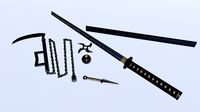
Ninja Kit
...rbosquid
royalty free 3d model ninja kit for download as fbx on turbosquid: 3d models for games, architecture, videos. (1672364)
turbosquid
$35

Brushes Kit
...osquid
royalty free 3d model brushes kit for download as max on turbosquid: 3d models for games, architecture, videos. (1216721)
turbosquid
$19
Medical kit
...osquid
royalty free 3d model medical kit for download as fbx on turbosquid: 3d models for games, architecture, videos. (1486089)