Thingiverse
probeClothespeg-001 by BETLOG
by Thingiverse
Last crawled date: 3 years ago
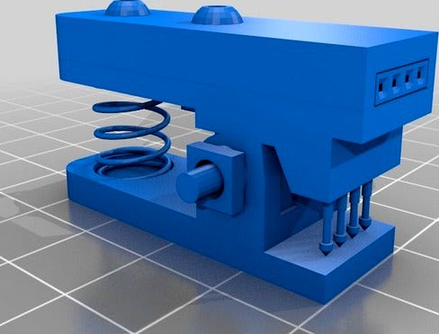
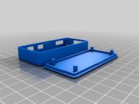
probeClothespeg-001
A simple way to secure pinless or pinned OLED displays for connection to arduino/pi/etc
Rotate the STL's yourself
No supports required.
0.4mm nozzle with 0.4mm external perimeters specified in your slicer are always assumed with my things.
Yes, the pins and spring I have included in the DISPLAY stl are accurate and good references for designing around these objects.
The DISPLAY stl, is just for assembly reference.
Uses:
1x M3x8mm(or 10mm) and nut
1x M3x10mm and nut
1x M3x20mm and 2xwasher and 2x nuts (or a single M3 nylock) (only one nut is shown in the DISPLAY stl, but i use two to lock them on)
4x Pogo Pin - P75-E2 Spring Test Probe https://www.aliexpress.com/item/50pcs-P75-E2-Dia-1-02mm-100g-Spring-Test-Probe-Pogo-Pin-Free-Shipping-Wholesale/813753643.html
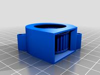
1x spring - 0.8Wire 10ODx15mm Long
1x dupont female 4socket....and wiring to suit.
NOTE:
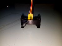
I used a 4socket female dupont inside the "peg" which is pretty much mandatory, so it stays inside the 'peg' and contacts the tops of the pogos correctly (see below)
I then attached wires - female terminals at both ends, leading to 4 individual 1socket duponts on the other end, into which i shove individual pins cut from a row of slightly extra long pin headers (if I need to gender bend it to plug into a breadboard). https://www.aliexpress.com/item/10PCS-40Pin-1x40-Single-Row-Male-2-54-17mm-Breakable-Pin-Header-Connector-Strip/32846204552.html
So this allows you to plug the OLED either in via the dupont, or by pinching it under the pogos, and optionally use the dupot as a connection for cables too.
Always confirm the order of wires from the OLED to the output you are connecting.
I colour code with dots on top of the peg above the pins, and then after following each wire to it's other end mark it with the appropriate colour. You always have to check the OLED pinout, and then find the colour on both ends before plugging it in, but it's pretty foolproof and flexible.
Assemble the top two parts, dupont and cables together with the 2 bolts, making sure the dupont has the exposed section of metal pointing downwards, THEN insert the pogo pins, they just sit in there, then add the bottom section and tighten the nuts, then shove the spring in.
A simple way to secure pinless or pinned OLED displays for connection to arduino/pi/etc
Rotate the STL's yourself
No supports required.
0.4mm nozzle with 0.4mm external perimeters specified in your slicer are always assumed with my things.
Yes, the pins and spring I have included in the DISPLAY stl are accurate and good references for designing around these objects.
The DISPLAY stl, is just for assembly reference.
Uses:
1x M3x8mm(or 10mm) and nut
1x M3x10mm and nut
1x M3x20mm and 2xwasher and 2x nuts (or a single M3 nylock) (only one nut is shown in the DISPLAY stl, but i use two to lock them on)
4x Pogo Pin - P75-E2 Spring Test Probe https://www.aliexpress.com/item/50pcs-P75-E2-Dia-1-02mm-100g-Spring-Test-Probe-Pogo-Pin-Free-Shipping-Wholesale/813753643.html
1x spring - 0.8Wire 10ODx15mm Long
1x dupont female 4socket....and wiring to suit.
NOTE:
I used a 4socket female dupont inside the "peg" which is pretty much mandatory, so it stays inside the 'peg' and contacts the tops of the pogos correctly (see below)
I then attached wires - female terminals at both ends, leading to 4 individual 1socket duponts on the other end, into which i shove individual pins cut from a row of slightly extra long pin headers (if I need to gender bend it to plug into a breadboard). https://www.aliexpress.com/item/10PCS-40Pin-1x40-Single-Row-Male-2-54-17mm-Breakable-Pin-Header-Connector-Strip/32846204552.html
So this allows you to plug the OLED either in via the dupont, or by pinching it under the pogos, and optionally use the dupot as a connection for cables too.
Always confirm the order of wires from the OLED to the output you are connecting.
I colour code with dots on top of the peg above the pins, and then after following each wire to it's other end mark it with the appropriate colour. You always have to check the OLED pinout, and then find the colour on both ends before plugging it in, but it's pretty foolproof and flexible.
Assemble the top two parts, dupont and cables together with the 2 bolts, making sure the dupont has the exposed section of metal pointing downwards, THEN insert the pogo pins, they just sit in there, then add the bottom section and tighten the nuts, then shove the spring in.
Similar models
grabcad
free

Pogo pin P75-E2
...pogo pin p75-e2
grabcad
pogo testing pin
grabcad
free

Pogo pins
...pogo pins
grabcad
different models of test probes
p058-q1
p50-e1
p50-q1
p75-e2
p100-e2
thingiverse
free
Sonoff Basic R2 Pogo Pins Header
...r soldering.
the pogo pins used are the p75-e2
the springs are random ones salvaged probably from an old xerox printer (no specs)
grabcad
free

pogo pin P75-B1
...pogo pin p75-b1
grabcad
testing pins with spring
thingiverse
free

TYWE3S Flashing Jig no alligator clips by SrGeek
...ia 0.68mm 75g pressure spring test probe pin
advantage you can keep all the wires, the jig and the ftdi adapter as a kit together
thingiverse
free

2x3p programming connector for OpenSprinkler 3.2 by stanoba
...n header (as shown on image)
solder wires
crimp dupont pins on other end
put pin header to casing and fix with hot-glue gun
thingiverse
free

Pogo-pin programming Adaptor by dnsseguin
...ean the hole with drill #55 (55mils)
i use pogo pin p100-e2,
screew: 92010a006
insert: 94459a120
nut: 90592a075
pogo: p100-e2
thingiverse
free

128 x 32 OLED Display - Holder by ale8oneboy
...re fit around the display from the front. there is not a bottom on the holder as it's part of a larger future project. enjoy!
thingiverse
free

Right Angle Plug for MicroLimit Switch to DuPont by TokyoDave
...d to have awg 20 wire inserted to act as internal wiring and dupont pins. both upward and downward facing variants are included.
grabcad
free

Spring Loaded Probes
...cts / pogo pins from multicomp and ingun (could be found by id in filename).
some of pogo-pins already inserted into sockets/cups
Betlog
thingiverse
free

dummy - barrel connector 5.5mm female by BETLOG
...- barrel connector 5.5mm female by betlog
thingiverse
a reference object i needed to make for "does it fit?" purposes.
thingiverse
free
DUMMY DC12V 40mm 4500RPM Brushless Fan Blower by BETLOG
...an blower by betlog
thingiverse
dummy/mockup/reference model of a
dc12v 40mm 4500rpm brushless fan blower
like the images shown.
thingiverse
free

Drill_bits_cylindrical_case-BETLOG-002 by BETLOG
...precise than needing to add 0.45 to 0.48...divided by two (0.225 to 0.24) to everything....0.4 divided by 2 is 0.2... and easier.
thingiverse
free

Z Leadscrew Rod Stabilizer - Flyingbear P902 by BETLOG
...e loud squeaking it makes when moving the z axis large distances.
connects to the 2020 frame by the usual m4 bolts and hammernuts
thingiverse
free

dummy - regulator 9-35V to 5v 5A by BETLOG
...e for "does it fit?" purposes.
2017-07-28 - replaced. previous version holes and width were incorrect enough to matter.
thingiverse
free
tool-capsuleFiller by BETLOG
...is to work reliably.
designed for size #00 caps.
requires 4x 0.8x10x15mm springs https://www.aliexpress.com/item/32963259463.html
thingiverse
free
Raspberry Pi Zero Case - BETLOG version by BETLOG
...precise than needing to add 0.45 to 0.48...divided by two (0.225 to 0.24) to everything....0.4 divided by 2 is 0.2... and easier.
thingiverse
free
calibration - quick - support angle by BETLOG
...el is small to print fast, and simulate almost worst case scenario where heater is always in fairly close proximity to the print.
thingiverse
free
fan guard - 60mm by BETLOG
...lades will almost always be the last time.
as always; assumes a 0.4mm nozzle. layer height is fairly irrelevant, but i used 0.3mm
thingiverse
free
BladeScraper by BETLOG
...t;hold" the blade so once you get it under the print yo can remove the block and just move the blade around under the print.
001
3d_export
$10

001
...001
3dexport
turbosquid
$1

001
... available on turbo squid, the world's leading provider of digital 3d models for visualization, films, television, and games.
3d_export
$15

bouquet 001
...bouquet 001
3dexport
bouquet 001 is a beautiful autumn decor for kitchen or bedroom
3d_export
$39

scene 001
...scene 001
3dexport
interior design scene 3d model<br>scene 001
3d_export
$20

fifteen52 outlaw 001
...fifteen52 outlaw 001
3dexport
fifteen52 outlaw 001.
3ddd
$1

PN-armchair-001
...pn-armchair-001
3ddd
pn-armchair-001
turbosquid
free

skirt 001
...001
turbosquid
free 3d model skirt 001 for download as blend on turbosquid: 3d models for games, architecture, videos. (1434052)
turbosquid
free

bra 001
...a 001
turbosquid
free 3d model bra 001 for download as blend on turbosquid: 3d models for games, architecture, videos. (1434044)
3d_export
$5

jacket 001
...jacket 001
3dexport
jacket_001
turbosquid
$100

moster 001
...bosquid
royalty free 3d model moster 001 for download as 3ds on turbosquid: 3d models for games, architecture, videos. (1235340)