GrabCAD
Pointed arch Gantry
by GrabCAD
Last crawled date: 3 years, 2 months ago
20/11/2020
I recently imagined that the vertical part of the running gear could have been telescopic by means of a possible truss system between each foot to compensate the increase in the lever arm (if necessary: depends on the height of deployment and the rigidity of the inflatable structure).
18/11/2020
Small additional informations on the ideas that guided me and thoughts after the fact ...
1) Why a pointed arch with shell architecture? The idea was to use as little gas as possible by maximizing the inertia of the beam / column, in the same way that one uses H or I sections rather than hollow cylindrical sections.
The pointed arch is for its part the most efficient to support a vertical load (slenderness factor: base / height ratio / load minupulation area).
At the same time, and afterwards, I realized that I should have opened the angle at the feet instead of having them parallel in order to eliminate the instability in flexion at this level. Ropes could also have been put between the weights to stabilize the whole, with a catapult and a catcher in the manner of a sewing machine shuttle to recover the rope, in order to free the space between the feet to get out of the lander.
2) Why drop-stitch panels?
So that this shell architecture (or skin) is foldable, deployable and that the webs of the beam have a certain rigidity in order to sufficiently make the lower section in reinforced fabric work in tension. Thus, the part working in compression mainly supports the payload and to a lesser extent the forces resulting from bending relating to the offset of the load. We can thus estimate that for a tube of 20cm in diameter and a pressure of 1 bar ablsolute, this is already 314 daN per foot (x4 = 1256 daN => G1.622 +/- 7500kg) + the compression linked to the offset.
3) Why a memory foam?
I mentioned memory foam mainly to help the structure unfold, but also to keep it in its shape in the absence of gas pressure. Afterwards, I said to myself that this foam, under certain conditions, could act like a muscle: if the pressure in a panel is suddenly increased and this foam has a certain resistance to the penetration of gas, the panel (the muscle) will suddenly inflate with a minimal amount of gas. This may allow a bent panel to be straightened out or force a violent effort. When the gas has penetrated slowly, we will have a stabilized pressure. As vacuum pumps have more and more difficulty pumping as the gas becomes scarce, the fact that the foam releases the gas slowly is therefore not a major problem.
4) Why running gear with two uncoupled wheels?
I admit that I considered that we could use a relatively high pressure in order to straighten the structure ... which is perhaps not the case because I had not thought of the weight that the auxiliary equipment would make. (batteries, photovoltaic panel deployment system, gas tanks ...) in all cases, they should be placed low enough to reduce the leverage during erection. For the tanks, I think if they are carbon or other composites and the gas used is of the correct molecular size, they should not be very heavy.
Also, the wheels should be large enough in diameter so as not to sink and maintain traction when they drag the equipment on the ground before inflation. It is also considering this that I planned that they could be articulated on 3 axes in order to find the ground presenting the best traction or to use only an inclined wheel to sink further into the ground.
Not having drawn the auxiliary equipment, I did not plan to protect them when they will be dragged ...
5) Why a rigid apex.
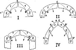
It is necessary to see the modes of collapse of the vaults (https://fr.wikipedia.org/wiki/Fichier:Rupture_de_voute.JPG) Certainly it is not rubble that will be used, but one can understand that the collapse at the apex will be done inward.
This "pyramidion" should therefore be large enough to distribute the force elsewhere on the structure (lower than what is drawn) and that it be articulated like the ribs of an umbrella to facilitate folding.
6) Other remarks.
The strips of anti-spacing fabric that I have placed between the panels can, if they are sufficiently stretched, serve as rungs to access the winch (which is not drawn either ...) and the load. This can be useful if something goes wrong.
I did not consider the interfaces between the different inflatable elements because it is a fairly substantial sewing job which is made even more complex by the fact that everything must be waterproof ...
However, I have in mind the way in which the sails of wood and canvas aircraft are assembled.
I'm sorry I didn't have the time to represent these concepts, but faced with a talented competition that produced quite substantial work, I didn't feel I had the means to compete ...
I hope these lines can be useful and wish everyone the best.
Yellow: drop stitch panel (with memory foam inside?)
Orange: inflatable tubes (compression)
Grey/black: tear resistant stretch fabric.
Magenta: Rope
Olive green: Rigid apex (pyramidion) connected to the lifting rope.
Stretch tear (with specific maximum extension) for reinforcement & stretch ability to make easier the foldability.
I recently imagined that the vertical part of the running gear could have been telescopic by means of a possible truss system between each foot to compensate the increase in the lever arm (if necessary: depends on the height of deployment and the rigidity of the inflatable structure).
18/11/2020
Small additional informations on the ideas that guided me and thoughts after the fact ...
1) Why a pointed arch with shell architecture? The idea was to use as little gas as possible by maximizing the inertia of the beam / column, in the same way that one uses H or I sections rather than hollow cylindrical sections.
The pointed arch is for its part the most efficient to support a vertical load (slenderness factor: base / height ratio / load minupulation area).
At the same time, and afterwards, I realized that I should have opened the angle at the feet instead of having them parallel in order to eliminate the instability in flexion at this level. Ropes could also have been put between the weights to stabilize the whole, with a catapult and a catcher in the manner of a sewing machine shuttle to recover the rope, in order to free the space between the feet to get out of the lander.
2) Why drop-stitch panels?
So that this shell architecture (or skin) is foldable, deployable and that the webs of the beam have a certain rigidity in order to sufficiently make the lower section in reinforced fabric work in tension. Thus, the part working in compression mainly supports the payload and to a lesser extent the forces resulting from bending relating to the offset of the load. We can thus estimate that for a tube of 20cm in diameter and a pressure of 1 bar ablsolute, this is already 314 daN per foot (x4 = 1256 daN => G1.622 +/- 7500kg) + the compression linked to the offset.
3) Why a memory foam?
I mentioned memory foam mainly to help the structure unfold, but also to keep it in its shape in the absence of gas pressure. Afterwards, I said to myself that this foam, under certain conditions, could act like a muscle: if the pressure in a panel is suddenly increased and this foam has a certain resistance to the penetration of gas, the panel (the muscle) will suddenly inflate with a minimal amount of gas. This may allow a bent panel to be straightened out or force a violent effort. When the gas has penetrated slowly, we will have a stabilized pressure. As vacuum pumps have more and more difficulty pumping as the gas becomes scarce, the fact that the foam releases the gas slowly is therefore not a major problem.
4) Why running gear with two uncoupled wheels?
I admit that I considered that we could use a relatively high pressure in order to straighten the structure ... which is perhaps not the case because I had not thought of the weight that the auxiliary equipment would make. (batteries, photovoltaic panel deployment system, gas tanks ...) in all cases, they should be placed low enough to reduce the leverage during erection. For the tanks, I think if they are carbon or other composites and the gas used is of the correct molecular size, they should not be very heavy.
Also, the wheels should be large enough in diameter so as not to sink and maintain traction when they drag the equipment on the ground before inflation. It is also considering this that I planned that they could be articulated on 3 axes in order to find the ground presenting the best traction or to use only an inclined wheel to sink further into the ground.
Not having drawn the auxiliary equipment, I did not plan to protect them when they will be dragged ...
5) Why a rigid apex.
It is necessary to see the modes of collapse of the vaults (https://fr.wikipedia.org/wiki/Fichier:Rupture_de_voute.JPG) Certainly it is not rubble that will be used, but one can understand that the collapse at the apex will be done inward.
This "pyramidion" should therefore be large enough to distribute the force elsewhere on the structure (lower than what is drawn) and that it be articulated like the ribs of an umbrella to facilitate folding.
6) Other remarks.
The strips of anti-spacing fabric that I have placed between the panels can, if they are sufficiently stretched, serve as rungs to access the winch (which is not drawn either ...) and the load. This can be useful if something goes wrong.
I did not consider the interfaces between the different inflatable elements because it is a fairly substantial sewing job which is made even more complex by the fact that everything must be waterproof ...
However, I have in mind the way in which the sails of wood and canvas aircraft are assembled.
I'm sorry I didn't have the time to represent these concepts, but faced with a talented competition that produced quite substantial work, I didn't feel I had the means to compete ...
I hope these lines can be useful and wish everyone the best.
Yellow: drop stitch panel (with memory foam inside?)
Orange: inflatable tubes (compression)
Grey/black: tear resistant stretch fabric.
Magenta: Rope
Olive green: Rigid apex (pyramidion) connected to the lifting rope.
Stretch tear (with specific maximum extension) for reinforcement & stretch ability to make easier the foldability.
Similar models
grabcad
free

Starshade
...-polyimide composite bladder initiates the polymerization method, and the structure becomes rigid with the help of inflation gas.
grabcad
free

ORIGAS - Origami Gas Inflated Panel - Heliostat design
...oldable surface.
it is designed to be deployed and locked once with only the gas pressure of small tanks located below the panel.
grabcad
free

Wire rope Tensairty structure lunar Gantry
...onsists of avionics and the linear actuating hoist for lifting utilizes efficient
lithium-ion and flexible lithium-ion batteries.
grabcad
free

ORIGAS - Origami Gas Inflated Panel
...oldable surface.
it is designed to be deployed and locked once with only the gas pressure of small tanks located below the panel.
grabcad
free

Omega Project
... combination of these two technologies makes it possible to create the lightest rigid structures of such proportions.
loading...
grabcad
free

Crane Structured - Inflatable Supported Lunar gantry
... mission.
thank you, nasa, for letting us participate and thank you, grabcad community, to take part in this challenging project!
grabcad
free

Inflatable Heliostat
...) or (3) part mixure that would mixed during inflation.
estimated weight: 109 lbs.
estimated package volume: 17,000 cubic inches
grabcad
free

Portable Lunar Inflatable Gantry
...of the inflatable components that roll out as the structure inflates. also included is a pdf that outlines details of the design.
grabcad
free

ALLGO crane (An Advanced Lightweight Lunar gantry for Operations)
... cover system. the load force is borne by this structure, but the tube is responsible for keeping the structure open and opening.
grabcad
free

Mobile Light Weight Lunar Inflatable Gantry
...rging.
the solar panel was designed to be tilted by electric cylinders to face the sun while operating to ensure continues power.
Arch
grabcad
free

Arch.
...arch.
grabcad
arch.
grabcad
free

Arch
...arch
grabcad
colourful arches!!
grabcad
free

Arche 2012
...arche 2012
grabcad
arche 2012
grabcad
free

Log Arch
...log arch
grabcad
log arch
grabcad
free

Arch Bridge
...arch bridge
grabcad
arch bridge
grabcad
free

Arch door
...arch door
grabcad
arch door
grabcad
free

Arch
...arch
grabcad
main building
grabcad
free

Arched Follower
...arched follower
grabcad
arched follower part for a car.
grabcad
free

arch
...arch
grabcad
металло деревянная арка
grabcad
free

Steel Arch
...steel arch
grabcad
segmented steel arch using solidworks
Gantry
grabcad
free

gantry
...gantry
grabcad
gantry
grabcad
free

Gantry
...gantry
grabcad
gantry
grabcad
free

Gantry
...gantry
grabcad
gantry assembly
grabcad
free

Gantry
...gantry
grabcad
gantry used for degreasing treated metallic products
grabcad
free

Gantry Assembly
...gantry assembly
grabcad
gantry assembly
- gantry for vslot 2040
- gantry for vslot 2020
- gantry for profile 2020
grabcad
free

gantry
...gantry
grabcad
100kg-4000kg
gantry robot
made in china 790688797@qq.com
grabcad
free

A gantry
...cture used to straddle an object or workspace
if u like my work follow on instagram @b_design3044
thank you
#b_design3044 team
grabcad
free

gantry
...gantry
grabcad
framing
grabcad
free

Gantry
...gantry
grabcad
loader
grabcad
free

gantry robot
...gantry robot
grabcad
gantry robot
Pointed
grabcad
free

Point On Curve
...o curves must be coincident and tangent in one point. create a point and a line tangent to the curve on this point for each part.
grabcad
free

power point
...power point
grabcad
power point
grabcad
free

axon.canter point
...axon.canter point
grabcad
axon.canter point
grabcad
free

lifting Point
...lifting point
grabcad
lifting point
grabcad
free

adjustable point
...adjustable point
grabcad
adjustable point
grabcad
free

Point filter
...point filter
grabcad
point filter
grabcad
free

Red Point
...red point
grabcad
red point
grabcad
free

Control Point
...control point
grabcad
control point
grabcad
free

PIVOT POINT
...pivot point
grabcad
pivot point
grabcad
free

Cup Point
...cup point
grabcad
cup point