Thingiverse
Piezo + FFC Extruder Head Cable PCB by pyr0ball
by Thingiverse
Last crawled date: 3 years ago
##Rev.E is incoming!
I've started over from scratch and built my own electrical design from the ground up. The new project can be found here
The new version has an onboard microcontroller to auto-calibrate on the fly, and a much more stable circuit with better filtering to prevent false positives.
I'll be posting it in it's own listing, as Rev.E is less universal, and more geared to "Mendel" style Cartesian printers like the i3 clones. The Rev.E print head board has only one change at this time which is using actual 0402 footprints and some better silkscreening as a result.
The Rev.D board for the print head is still compatible with the Rev.E Control/X-Car board chain as well. I'm sure eventually I'll figure out a more intuitive way of naming all of these boards eventually.
In future I may add circuitry for alternate temperature sensors. Let me know what you think about adding an RTD PT100 circuit or a thermocouple amp
~Edit 12/15/2017: The 5v voltage regulators on the BOM are not capable of handling +24v input. I'm currently seeking out replacements that will work at higher ratings. I'll update the BOM with the correct size of resistors and caps at the same time.~
BOM has been updated with higher rated components and passives using the proper 0805 footprints
Cus we all know how much fun soldering grains of sand is right? RIGHT?
Rev.D Has been added!
Changes - 1/30/2018:
Changed footprint spacing on connectors to allow for use of standard JST enclosed headers
Moved fan voltage regulator supply to the control board side of the chain
Replaced voltage regulators with a single LM317 @1.5A. Voltage selection is now handled via changing the vref_adj.
Replaced PZ20 circuit's LDO with a simpler model with higher input voltage range
Added second LDO for dedicated supply to LED's
Isolated TH1 from ground plane to address vdroop effecting thermal readings
Added grounding vias for edges and isolated areas of ground plane
Added decoupling capacitors to power inputs
Added "personal touch" graphic
Rev.C has been added!
This design revision includes three improvements:
Fixed the hole size for the fan and sensor headers, and gave them a little more space
Attempted to clean up and add better labeling
Added a set of solderable pads on the edge of the board for pulling Vcc/12v/5v as needed for extra goodies on your print head
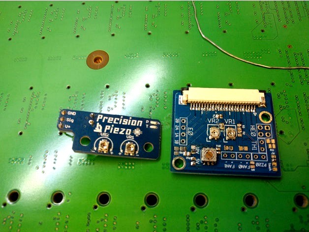
This is a concept board design that handles several different things to make managing your extruder head easier.
Features:
Precision Piezo Circuit built-in for z-probing. (Big thanks to precisionpiezo.co.uk for making their schematics available to the public!)
On-board Voltage Regulators allow the user to select either 5V or 12V fans, even when their printer is using 24V (cus aren't 24v fans just so much harder to find?)
LED feedback of each component, including heaters, fans, and touch sense
Uses a 24-pin 1mm pitch Flat Flexible Cable for routing between the print head and the control board, allowing for great flexibility and a very clean cable system
Included files are the original cad files designed in PCBWeb Available online for free, an up-to-date BOM using Digikey parts, and Gerber file exports formatted for Seeed Studio Fusion PCB
Please let me know if you have any feedback, or would prefer a different pinout. If you have other feature suggestions, I'd be happy to integrate them!
Update 11/27/2017
I've designed and uploaded a modified X-Carriage that should allow almost complete compatibility with most of the open source print heads out there that are designed for the Prusa/Anet style of printer. The Piezo disk sits in between the print head an the X-Carriage, and is flexed along the Y-axis when the nozzle touches the bed.
I've started over from scratch and built my own electrical design from the ground up. The new project can be found here
The new version has an onboard microcontroller to auto-calibrate on the fly, and a much more stable circuit with better filtering to prevent false positives.
I'll be posting it in it's own listing, as Rev.E is less universal, and more geared to "Mendel" style Cartesian printers like the i3 clones. The Rev.E print head board has only one change at this time which is using actual 0402 footprints and some better silkscreening as a result.
The Rev.D board for the print head is still compatible with the Rev.E Control/X-Car board chain as well. I'm sure eventually I'll figure out a more intuitive way of naming all of these boards eventually.
In future I may add circuitry for alternate temperature sensors. Let me know what you think about adding an RTD PT100 circuit or a thermocouple amp
~Edit 12/15/2017: The 5v voltage regulators on the BOM are not capable of handling +24v input. I'm currently seeking out replacements that will work at higher ratings. I'll update the BOM with the correct size of resistors and caps at the same time.~
BOM has been updated with higher rated components and passives using the proper 0805 footprints
Cus we all know how much fun soldering grains of sand is right? RIGHT?
Rev.D Has been added!
Changes - 1/30/2018:
Changed footprint spacing on connectors to allow for use of standard JST enclosed headers
Moved fan voltage regulator supply to the control board side of the chain
Replaced voltage regulators with a single LM317 @1.5A. Voltage selection is now handled via changing the vref_adj.
Replaced PZ20 circuit's LDO with a simpler model with higher input voltage range
Added second LDO for dedicated supply to LED's
Isolated TH1 from ground plane to address vdroop effecting thermal readings
Added grounding vias for edges and isolated areas of ground plane
Added decoupling capacitors to power inputs
Added "personal touch" graphic
Rev.C has been added!
This design revision includes three improvements:
Fixed the hole size for the fan and sensor headers, and gave them a little more space
Attempted to clean up and add better labeling
Added a set of solderable pads on the edge of the board for pulling Vcc/12v/5v as needed for extra goodies on your print head
This is a concept board design that handles several different things to make managing your extruder head easier.
Features:
Precision Piezo Circuit built-in for z-probing. (Big thanks to precisionpiezo.co.uk for making their schematics available to the public!)
On-board Voltage Regulators allow the user to select either 5V or 12V fans, even when their printer is using 24V (cus aren't 24v fans just so much harder to find?)
LED feedback of each component, including heaters, fans, and touch sense
Uses a 24-pin 1mm pitch Flat Flexible Cable for routing between the print head and the control board, allowing for great flexibility and a very clean cable system
Included files are the original cad files designed in PCBWeb Available online for free, an up-to-date BOM using Digikey parts, and Gerber file exports formatted for Seeed Studio Fusion PCB
Please let me know if you have any feedback, or would prefer a different pinout. If you have other feature suggestions, I'd be happy to integrate them!
Update 11/27/2017
I've designed and uploaded a modified X-Carriage that should allow almost complete compatibility with most of the open source print heads out there that are designed for the Prusa/Anet style of printer. The Piezo disk sits in between the print head an the X-Carriage, and is flexed along the Y-axis when the nozzle touches the bed.
Similar models
thingiverse
free

Fan cooled Voltage Regulator Housing - XH-M411 by bvogl
...o attach the fan.
the photo shows a prototype unit. the downloadable thing has a slot for the fan cable directly next to the fan.
grabcad
free

24V Input 5V Out Optocoupler
...24v input 5v out optocoupler
grabcad
24v input 5v out optocoupler isolation control 8 ch solated input signal board
grabcad
free

1584en Mini Buck Converter Voltage Regulator Module Adjustable DC 4.5 to 24V -- 15 W unit from WEEWOODAY
... voltage by soldering the pot on the board, and you can adjust the fixed output voltage by turning the potentiometer as you need.
grabcad
free

MP2315 Mini Buck Converter Voltage Regulator Module Adjustable DC 4.5 to 24V -- 15 W unit from WEEWOODAY
... voltage by soldering the pot on the board, and you can adjust the fixed output voltage by turning the potentiometer as you need.
thingiverse
free

Rumba fan holder for 50 mm fans by rchobby
...the voltage is taken from rumba board with short cables. the assembly of the fan bracket via spacers with 3 mm holes and threads.
grabcad
free

Mini Buck Converter Voltage Regulator Module Adjustable DC 4.5 to 24V -- 15 W unit from WEEWOODAY
... voltage by soldering the pot on the board, and you can adjust the fixed output voltage by turning the potentiometer as you need.
thingiverse
free

Case for 6CH rotary knob servo driver controller board by mjdorma
...d a 5v power input plus a vcc input directly from the battery.
battery 7.4v 400mah 30c 2s
dc voltage regulator (calibrated to 5v)
grabcad
free

L7805CV Voltage Regulator
...39;s input voltage can be 7v to 37v and the output voltage will hold steady at 5 volts even if the input voltage goes up or down.
thingiverse
free

40mm Fan Case for Pololu D24V150Fx Voltage Regulators by AntaresAdroit
...
-3d printed case bottom
-40mm fan
-4x fan mounting screws
-4x #2-56 3/4″ length phillips machine screw
-4x #2-56 machine hex nut
thingiverse
free

Eryone Thinker S 5015 blower
...r fan and run it to the positive of e1 on the board. that way will allow you to run the blower on 24v and all the rest remain 5v.
Pyr0Ball
thingiverse
free

RJ45 Keystone Socket by pyr0ball
...rj45 keystone socket by pyr0ball
thingiverse
just an stl export of mwu's keystone, which was posted only in scad
thingiverse
free

MK10 Nozzle Dummy Model by pyr0ball
...mk10 nozzle dummy model by pyr0ball
thingiverse
a model of the mk10 extruder nozzle, useful for modelling extruder parts
thingiverse
free

Mk8 Nozzle Dummy Model by pyr0ball
...mk8 nozzle dummy model by pyr0ball
thingiverse
just a dummy model for the mk8 nozzle. usedul for modelling parts for your hotend
thingiverse
free

Precision Piezo Dummy Model by pyr0ball
... dummy model by pyr0ball
thingiverse
a dummy model for reference when building a mount for precision piezo's piezo20 0.6 pcb
thingiverse
free

Diamond Mixing Nozzle Dummy Model by pyr0ball
...g nozzle dummy model by pyr0ball
thingiverse
just a dummy model of the diamond hotend nozzle for use in developing other designs
thingiverse
free

Scalpel Holder for Slotted Pegboard by pyr0ball
...giverse
remix of franklumien's scalpel holder designed to use slotted pegboard clips instead.
wip, still adjusting spacing.
thingiverse
free

Keystone Receptacle Wall Plate by pyr0ball
...y of the remixed rj45 keystone receptacle, i decided to make wall plates for it. there's single, dual, quad, and hex versions
thingiverse
free

Adafruit Single-Channel Relay Dummy Model by pyr0ball
...ngle-channel relay dummy model by pyr0ball
thingiverse
just a dummy model for the adafruit relay module for use in other designs
thingiverse
free

Slotted Pegboard Modular Clip by pyr0ball
...pegboard organizers.
using a corresponding anchor hole, these can be added to almost any kind of organizer bin, rack, or toolset.
thingiverse
free

Small Things Organizer Shelf for Slotted Pegboards by pyr0ball
...s excellent small items organizer. only one small addition and it's now compatible with wall control style slotted pegboards!
Ffc
3d_export
$10

ffc soft flat wire punching machine and ccd visual inspection equipment
...on equipment
3dexport
mobile phone ffc blanking machine, ffc soft flat wire punching machine and ccd visual inspection equipment
3d_export
$20

wire laser cutting peeling cutting machine ffc cutting machine
...and receiving machine, with the structure of this drawing, you don't need to draw by yourself, welcome to collect, thank you.
3dfindit
free

FFC Accessories
...ffc accessories
3dfind.it
catalog: te connectivity
3dfindit
free

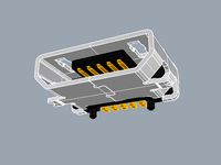
FFC Connectors
...ffc connectors
3dfind.it
catalog: te connectivity
3dfindit
free

FFC Contacts
...ffc contacts
3dfind.it
catalog: te connectivity
thingiverse
free

Cable Clip for FFC Cables by nad_22
...cable clip for ffc cables by nad_22
thingiverse
this is a simple clip for mounting ffc cables to what ever ;-)
thingiverse
free

FFC to FFC adapter extension clamp for Geeetech A10 by Deejayshag
... effectively for other ffc cables as well, as long as they have less than 40 pins (think raspberry pi camera, which has 15 pins).
thingiverse
free

V Slot FFC Cable Clamp by firepower9966
...usion.
need this to keep my geeetech lcd interface tidy and safe.
print two stand upright to go on either side of ffc to hold it.
thingiverse
free

Quanum V2 FFC Mount by hpz937
...ount for the crazepony 700tvl fpv camera. mount was then hot glued to quanum v2 monitor.
camera dimensions 12.5mm x 12.5mm x 6mm
thingiverse
free

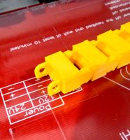
BCN3D+ cable chain + ffc cable by AlexQuad
...er, solution for cables cuts in the extruder.
the chain is from http://www.thingiverse.com/thing:11978http://youtu.be/ymd8anl5bni
Piezo
turbosquid
$5

Buzzer Piezo
...odel buzzer piezo for download as max, max, 3ds, fbx, and obj on turbosquid: 3d models for games, architecture, videos. (1607700)
3d_export
$7

buzzer piezo
...;all materials are logically named<br>the main format is in 3ds max 2013.<br>satisfaction guarranteed<br>thanks
3d_export
$15

Buzzer 3D Model
...audio electronic component signalling piezoelectric disk alarm timer electric piezo industrial part electrical bell doorbell buzzer 3d model download...
thingiverse
free

Hypercube_evolution E3D_Titan_Aero with piezo
...ercube_evolution e3d_titan_aero with piezo
thingiverse
hypercube_evolution a piezo z-axis sensor was attached to e3d_titan_aero.
thingiverse
free

Precision-Piezo Probe with 3 Piezo 15mm by Tech-Raton
...if bigger, you'll lose the piezo marks)
you just have to slide the part between the heatsink and the effector (or your mount)
thingiverse
free

Piezo Chimera mount by RKS7204
...piezo chimera mount by rks7204
thingiverse
mount for e3d chimera hotend and piezo sensor
thingiverse
free

Piezo v1.22 Mount by Suggy
...piezo v1.22 mount by suggy
thingiverse
mount for under bed piezo censor pcb
thingiverse
free

Precision Piezo - 27mm and 20mm Piezo Disc drill guide. by DjDemonD
... djdemond
thingiverse
drilling guide for piezo discs to centre your drill.
see youtube video here: https://youtu.be/ms1fd0v5z68
thingiverse
free

Underbed Piezo Mounts by fcollingwood
...the piezos are smooth. two of the arms a required and two of the mirror arms are required
everything else can be printed at 0.2mm
thingiverse
free

(Beta) Piezo UnderBed Mounts by Precision Piezo by DjDemonD
...sulation to the mounts to keep heat from the bed away from the piezos.
future release might include some clamps on the top parts.
Pcb
turbosquid
$19

PCB assembly line.
...mbly line. for download as 3ds, max, ige, obj, stl, and sldas on turbosquid: 3d models for games, architecture, videos. (1330649)
3ddd
$1

GRAMERCY HOME - CARMELA ARMCHAIR 602.023-PCB
...gramercy home - carmela armchair 602.023-pcb
3ddd
gramercy home
gramercy home
carmela armchair
602.023-pcb
www.gramercy-home.ru
3d_export
$150
auto pcb board loder inspection machine
...auto pcb board loder inspection machine
3dexport
auto pcb board loder & inspection machine --> only step file
3d_export
$7
turning mechanism drawing pcb board turnover machine
...turning mechanism drawing pcb board turnover machine
3dexport
turning mechanism drawing pcb board turnover machine
turbosquid
$9

Stereo Jack 3.5mm for soldering to a PCB
... available on turbo squid, the world's leading provider of digital 3d models for visualization, films, television, and games.
3d_export
$5

LED Right Angled PCB Mounting
...m led. step and igus files. multiple led colors: blue, purple, red, green, and yellow. dimensions case w 4,5mm , h 7,3mm l 6,4mm.
3d_export
$20
automatic pcb loading and unloading dispensing test automatic line
...ment structure is very complex. it is a very practical equipment for smt industry. the equipment is mature application equipment.
3d_export
$18
an automatic line for fct function test of pcb
... drawings are downloaded, you can directly watch and edit the contents. welcome to download and learn from your favorite friends.
3d_export
$5
USB Micro B connector
...step and igus for 3d import into ecad tools, pcb footprints. added also a altium designer pcb component library...
3d_export
$15
plastic housing with dewalt battery holder
...case measures 155x106x60. inside the case there are two pcb of 130x98 and 98x42...
Extruder
3ddd
$1
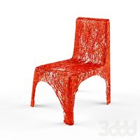
Extruded Chair
...extruded chair
3ddd
extruded , tom dixon
inspired by tom dixon extruded chair
turbosquid
$15
Extruded Table
... extruded table for download as blend, dae, fbx, obj, and stl on turbosquid: 3d models for games, architecture, videos. (1634137)
turbosquid
$2
3D Printer Extruder
...d
royalty free 3d model 3d printer extruder for download as on turbosquid: 3d models for games, architecture, videos. (1537359)
turbosquid
$1
Zombie extruded text
...oyalty free 3d model zombie extruded text for download as obj on turbosquid: 3d models for games, architecture, videos. (1322198)
turbosquid
$4

Extruder conical screw
...el extruder conical screw for download as sldpr, ige, and stl on turbosquid: 3d models for games, architecture, videos. (1524433)
turbosquid
$50
3d PRINTER - Extruder
... available on turbo squid, the world's leading provider of digital 3d models for visualization, films, television, and games.
turbosquid
$15
Extruded Table 2
...xtruded table 2 for download as blend, dae, fbx, obj, and stl on turbosquid: 3d models for games, architecture, videos. (1621846)
turbosquid
$10
Maya Extrude Tool
... available on turbo squid, the world's leading provider of digital 3d models for visualization, films, television, and games.
3d_export
$5

world earth extrude map
...world earth extrude map
3dexport
3ddd
$1

Simply Elegant Extruded Tree Coffee Table Design
...ble by link studios. the silhouette of a tree is visible at one angle, extruded from the surface to create the support structure.
Cable
3d_export
free

Cables
...cables
3dexport
cables for your purposes
3d_export
free
cable belt for cable organization
...ze your cables in 3d printers. it will bend only to one direction. the area to put the cables per piece is aprox. 1,6cmx2,6cmx1cm
3d_ocean
$16
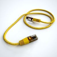
Ethernet Cable
...ethernet cable
3docean
cable computer electronics ethernet internet network connected
ethernet cable 3d model
3d_export
$65

cable
...cable
3dexport
simple rendering of the scene file
turbosquid
$14

Cable
...l cable for download as ma, max, fbx, 3ds, gltf, obj, and stl on turbosquid: 3d models for games, architecture, videos. (1631358)
3ddd
$1
Cable Cover
...cable cover
3ddd
кабель
vertebra passacavo - cable cover
max + vray 2.20.03
3d_export
$15
Cable reel
...without cable. textures 4k 4096x4096 targa, png, jpeg.<br>number of polygons without cable: 2896<br>with cable: 35328
3d_export
$7

short cable
...short cable
3dexport
rubber cord. very detailed. cable thickness: 2.55 mm total length: 55mm
3d_export
$5

USB CABLE
...usb cable
3dexport
turbosquid
$30
Cable Reels
...osquid
royalty free 3d model cable reels for download as fbx on turbosquid: 3d models for games, architecture, videos. (1439507)
Head
3d_export
$5

head
...head
3dexport
simulated female head.
3d_ocean
$5

Deer Head
...deer head
3docean
deer head
simple model of deer head with neck.
cg_studio
$25

Marble Head - Head A3d model
... - head a3d model
cgstudio
.ma - marble head - head a 3d model, royalty free license available, instant download after purchase.
turbosquid
$5
Head
...ad
turbosquid
royalty free 3d model head for download as max on turbosquid: 3d models for games, architecture, videos. (1230068)
turbosquid
free

Head
...
turbosquid
royalty free 3d model head for download as blend on turbosquid: 3d models for games, architecture, videos. (1276899)
turbosquid
free

The Head
...urbosquid
royalty free 3d model the head for download as max on turbosquid: 3d models for games, architecture, videos. (1386205)
3d_export
$10

bull head
...bull head
3dexport
bull head
3d_export
$5

girl head
...girl head
3dexport
head girl
3d_export
$5

Tigger-head
...tigger-head
3dexport
tigger-head
3d_export
$5

head on a spear
...head on a spear
3dexport
head on a spear