Thingiverse
Pi Pico project solar power charger box by Fluby
by Thingiverse
Last crawled date: 4 years, 5 months ago
What's this then?
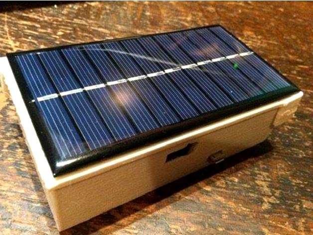
I wanted to power my pico projects free from the mains, but also bring the unit indoors to either program or charge.
If course you could just use this as just a pico project box, or just a charger box. Remix to your requirements.
.
Power in either micro USB power, or the 6V solar panel.
Power Out via USB A socket, or you could also easily run wires straight to an internal Pico.
Battery is standard 18650 - get one from an old laptop power pack.
Solar panel chosen at 6V 0-200mA 1W. It fits the lid. You could use what you have.
Base
The base has various holes, for power in and out, the OLED display, the pico usb port and one extra random USB A size hole so you can run Input/output for your project. Also some holes at the bottom if you want to screw it down.
Lid
Choice of 2 lids, I printed v2 which holds securely has a fix hole for M3 screw to close, and helps location but needs more work. V1 is simpler and should work fine. It kind of clicks on and stays there.
Where to put the Pico
You could house your pico within, or outside.
The internal pico mount is remixed from https://www.thingiverse.com/thing:4748043
I just cut out the base for cooling, and made the lugs a little bit longer. Tricky to print I had to clean the lugs up a bit before the pico fitted.
Fixing and sealing
While this isn't waterproof, hot glue could make it more so.
Hot glue will seal any bits in
Parts
Search for these:
A: 4pin Type A FEMALE USB to 2.54mm DIP PCB Breakout Board SIP Adapter
B: 6V Solar Panel Cell Epoxy 1W for DIY Solar Projects (110*60)
C: USB MCP73871 DC Solar Lipoly Lithium Lon Polymer Charger 3.7/4.2V Battery Module
-C(ii): optional if you want t prevent over heat or overcool when charging: MF52D 3950 1% High Precision NTC Leaded Thermistor
D: Female Micro USB to DIP Adapter Converter 2.54mm PCB Breakout Board
E: Plastic Battery Case Holder Storage Box For 18650 Batteries 3.7V & Wire Black
F: White 128X64 OLED LCD LED Display Module For Arduino 0.96" I2C (or similar, if you want, but size 27MM 27MM 4.1MM fits)
F: ...and an 18650 battery (old laptop or vape)
G: (pi pico of course)
Guides
Charger - this is excellent:
https://learn.adafruit.com/usb-dc-and-solar-lipoly-charger/using-the-charger
there's loads of data about it on the web.
my board: https://www.diymore.cc/products/mcp73871-usb-dc-solar-lipoly-lithium-lon-polymer-charger-3-7-4-2v-battery-module?_pos=146&_sid=42c547366&_ss=r
Connections of parts
A: Connected to LOAD and GND on C
B: Connected to PWR and GND on C
C: The charger board
Cii: (optional) connected to the 'therm' holes - remove the SMD resistor if you do.
D: Connected to the + and - next to the PWR corner of C
E: Connected to BAT and GND on C
F: plugged into E
G: whether inside or outside, connected to A using normal USB A to micro USB cable. You could connect LOAD to pin 39 (VSYS - which converts the USB voltage to 3v3) and GND to pin 36 if the Pico is in the box - at your risk....
Charge status
There are onboard LEDs - see the datasheet. The walls are so thin I can see the LED's flashing on the solar charge which is good enough for me. There are 3 LED's on this board. The combinations tell you different things - all very complicated as they are all red!
However, part C (MCP73871) apparently allows for external LED's if you want to know what's going on charge-wise. Its probably easier to drill holes for these if you do. On my board stat1 and stat2 are on the 'C, +, D' holes. You could use different colours then....