Thingiverse
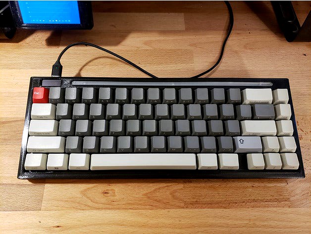
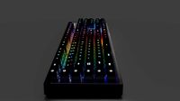
PF68 68 key keyboard with LCD, RGB, captured hot swap sockets by GH_Leslie
by Thingiverse
Last crawled date: 3 years ago
This came about after seeing various hot swap boards that didn;t work how I wanted.
After a lot of false starts using other designs I started from scratch and came up with this. The Hot swaps are held captive between the "pcb" and base plate so they can actually function as hot swaps, holding themselves in place. Best of all, no pcb to be damaged during swaps either.
Geekhack page with a bit more documentation about this project:https://geekhack.org/index.php?topic=109345.0
Printing test and template for the socket system is here:https://www.thingiverse.com/thing:4791698
Warning!!!!!This is as done as this project will get. If you want help it's better to catch me on GH however don't expect much help as I don't recommend actually building this as it is, remix it, use someone else's remix. The difficult part of the design is done but I'm burnt out on this project.
Warning #2
There's a lot of info here and it's necessary if you plan on building this.
Take note, there is NO FIRMWARE included, there is a keymap but nothing more, this is because how you wire from the PCB to the Teensy changes the firmware and it's honestly better to remap the firmware than try to redo the wiring. It will take a while but worth it, especially since once you do it you can do any board you want. This is why no one includes firmware, you would have to micro manage every last wire.
Notes: (Important stuff!)
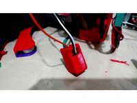
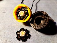
While mine is done, this is a horrible project if I'm honest. I'm posting this so others can use the hot swap system and steal ideas but it's not an easy build, the wiring channels are really, really tight. Also note that unless you duplicate my exact pinout your firmware will not work, so it's a lot of tedious bits that if done wrong will need reworking. Also unless you have a large printer you will need to cut up the body. For RGB I simply drilled a hole through the base and foot and routed power, ground and signal, to get RGB underglow, it's not built in, just attached to the bottom (sorry no glamour shots, this was mostly to see if it worked). The mini B cable into the Tensy was expected to be used, I ran out of room and patience and just soldered direct to the board, a bit more hacking with a hot knife or minor changes and it could work but after doing it, I'd probably just solder it direct again.
Bottom line, remix it, don't use it as is.
It was a nice idea and it works, it's just not easily reproduced.
Features:
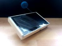
Very low profile, the body flat and extremely thin (11mm to top of plate, less than 1/2in).
Easy to print, (near) vertical walls means no stairstepping
Kailh hot swap sockets are locked in place yet easily replaced if they go bad.
PCB and plate mount switch compatible (no more trimmed legs!)
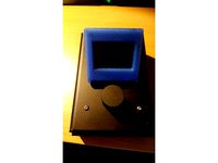
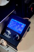
LCD to display layer and hotkeys
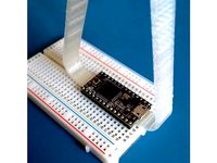
Teensy 2.0 with QMK so it's programmable.
RGB (sort of)
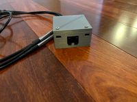
Port is a Mini B, Micro B or Type C depending on choice of breakout board (Adafruit).
Trim is replaceable for easy color swaps, I have two types, flat/flush and pencil grooved and is replaceable without no disassembly of the keyboard.
Status:
Everything printed, tested and working.
Parts needed:
About 1.1kg of plastic (see below for recommendations)
Teensy 2.0
0.91 Inch I2C SSD1306 OLED Display (Amazon)
Kailh Hot Swap sockets
Adafruit USB breakout board (see below)
rubber feet (10x10x2.5mm Kitchen Cabinet Door Pad silicone squares, amazon)
wire (I used solid core cat5 for the pcb and an old usb cable for the breakout)
solder
Switches and keycaps
3x M5x15mm bolts (or similar, just put them in hot to create new threads)
15x #2 screws (or similar, just put them in hot to create new threads)
Flux, you need flux to tin the hot swaps, it's MUCH easier. Rosin core will clog them if you rely on that one to tin them.
Breakout board links (available from other places)
Mini B - https://www.adafruit.com/product/1764
Micro B - https://www.adafruit.com/product/1833
Type C - https://www.adafruit.com/product/4090
:::::Tips:::::
Printing
Petg works, but at this scale it can be a bit of a challenge. Forget ABS, too large and too much shrinkage. If you plan to chop it into parts ABS and PLA are fine, but nothing really likes sticking to PETG.
Beware stuck support under the LCD, the top has a habit of ripping off the overhang, be gentle here. It shouldn't be a huge problem on PLA but it can be on PETG.
PETG will give you a more satisfying thunk, more like a plastic board with an aluminum plate, almost as stiff as one as well with 30% infill. PLA will give you a higher pitch sound but will also be stiffer and easier to print. It's also more likely to deform over time, hence my use of PETG. If you can do it as a single part, I would use PETG again, it just sounds more solid.
You only need support under the lower overhangs on stabs and under the LCD, everything else prints great as you would expect. Beware heat soak from retraction on the base, I made the pegs larger which helps but if you keep failing here that's likely your problem. Strings are better than failure, you have been warned.
If you use the parts labeled "with pads" they have breakoff tabs that help hold the parts down and stable. They have a 0.1mm separation gap so they should snap off relatively clean and not leave an exposed infill pattern. On the top and base you may need to hot glue or CA glue these to your bed to get adequate adhesion, especially with PETG. Beware, doing such things can destroy print beds, particularly Borosilicate glass. There's more tips on how I printed these in the Geekhack thread at the top of the page. I did not use a heated bed.
VERY VERY important!!
The base, and pcb need to be printed 90 degrees from the rest of the parts. The reason for this is printer skew. You may think your printer's X and Y axis are a perfect 90 degrees but have you ever actually tested and verified it over long distance? Two 30mm parts fitting together is a lot different than two parts ten times that size fitting together. I loosened the tolerances to help but we're talking tenths of a mm across 300mm span, this is particularly an issue for CoreXy where the belts can twist the carriage.
Assembly
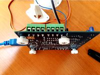
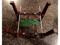
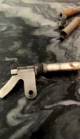
Build the pcb, if you look one pic shows it with stubs hanging, I did this using the diode legs and solid core cat5 cable so it's stiff. From this you can solder jumpers from here to the Teensy. A few Teeny I/O pads line up with the collums, use those when you can.
The pcb should lay in the base flush, or very little sticking up, /25mm or so, if it sticks up more than that, like the thickness of a wire it means it's not sitting flush against the base. You need it to push down all the way in order to support the hot swaps.
LCD presses in from under then the lcd support bolts in holding it up, beware wiring.The little C shaped clip labeled USB support sits under the LCD and lcd support and clamps down the usb breakout board. alternatively you could just hot glue the breakout board in place or just leave it without anythin, it has very little wiggle room regardless. Top and base sandwich the pcb, use the #2 screws around the perimeter.
Trim is inserted from the top, and screwed in from below using #2 screws and this must be done before you install the foot which is done last.
Assembly Tips
Whatever you wire from the Teensy to the USB breakout, beware, some companies swap the wire color codes.
Insert small hot swap end first.
Do NOT push on the metal, if you need to exert any force on the swaps, push against plastic. If you damage a metal clip, toss that swap, don't try and use it. Swap sockets are cheaper than switches, not to mention desoldering and dealing with wiring. You may be able to bend it back but these already have a limited lifespan and you damaged it, how long will it last now? If you insist on using it for instance you have no spares, put it on left control, or any bottom row keys as these will be the easiest to replace later.
Soldering
The hot swap are not pre-tinned on the flat tops where we will be soldering, technically we're soldering to the opposite side they intended. Do a small pre-tin, I HIGHLY recommend getting a tiny brush (trim it down to really small) and apply soldering paste. Using Rosin core solder works, but it's very easy to damage a socket. Beware getting too much solder, you can get extra on the outside ends, but if you get any solder on the inside contacts the hot swap is ruined. Expect to ruin a couple, the solder flux helps a lot by allowing less to do the job but will probably still ruin one or two. Seriously this helped a TON.
Solder the columns first then the diodes, it makes it easier to run, I did it in reverse and it created some issues. Wire the whole thing as stubs as shown in the pcb pic, then attach jumpers from the controller to the stubs this way you keep it all as tight as possible.
Bending Diodes, on the negative side leave 2mm clearance then bend 90 degrees. On the positive side bend the lead immediately out of the diode until it intersects the other lead at a 45 degree angle. If you need wiring to go from one diode to another, you can use the legs you cut off from others as jumpers Don't worry if each diode looks bad individually when starting, as a group they look good by the time you get a few soldered.
Don't start with the top row, it needs to be tucked in tight and you want to practice bending the others first.
It's plastic, if something gets in your way, melt it and make some room. Just beware the pegs from the base, if you intrude on those you will need to alter them as well. Try and keep things flush as there is no room to spare between parts. This is why this is such a challenging project.
If stabs will not go in, clean up underside support, space bar is especially fickle.
If you do break off a few small bits of the top plate, it will likely be fine.
Screws
The M5 holes for the foot are threaded, the rest are not.
You can run a tap through the M5 but it's not necessary, just put the bolts/screws in a thread or two then hit them with a lighter (use the blue part of the flame), when it starts to sag or lean, screw it, then allow it to cool. Do this during a prefit without the mating art or you may melt them together. A lighter works better to create threads than a tap for smaller screws in PLA or PETG, this can also be used to repair threads.
The screws for the housing are #2 screws you can get at any hardware store but any small screw will work. Beware the pencil trim (grooved) if you use #2 it's easy to poke out the tips, I recommend trimming off a mm or so off the tips. Not necessary if you use the flat trim.
I recommend using the heated screws to create threads on all the parts prior to final assembly to make it easier and ensure you don't melt things together.
After a lot of false starts using other designs I started from scratch and came up with this. The Hot swaps are held captive between the "pcb" and base plate so they can actually function as hot swaps, holding themselves in place. Best of all, no pcb to be damaged during swaps either.
Geekhack page with a bit more documentation about this project:https://geekhack.org/index.php?topic=109345.0
Printing test and template for the socket system is here:https://www.thingiverse.com/thing:4791698
Warning!!!!!This is as done as this project will get. If you want help it's better to catch me on GH however don't expect much help as I don't recommend actually building this as it is, remix it, use someone else's remix. The difficult part of the design is done but I'm burnt out on this project.
Warning #2
There's a lot of info here and it's necessary if you plan on building this.
Take note, there is NO FIRMWARE included, there is a keymap but nothing more, this is because how you wire from the PCB to the Teensy changes the firmware and it's honestly better to remap the firmware than try to redo the wiring. It will take a while but worth it, especially since once you do it you can do any board you want. This is why no one includes firmware, you would have to micro manage every last wire.
Notes: (Important stuff!)
While mine is done, this is a horrible project if I'm honest. I'm posting this so others can use the hot swap system and steal ideas but it's not an easy build, the wiring channels are really, really tight. Also note that unless you duplicate my exact pinout your firmware will not work, so it's a lot of tedious bits that if done wrong will need reworking. Also unless you have a large printer you will need to cut up the body. For RGB I simply drilled a hole through the base and foot and routed power, ground and signal, to get RGB underglow, it's not built in, just attached to the bottom (sorry no glamour shots, this was mostly to see if it worked). The mini B cable into the Tensy was expected to be used, I ran out of room and patience and just soldered direct to the board, a bit more hacking with a hot knife or minor changes and it could work but after doing it, I'd probably just solder it direct again.
Bottom line, remix it, don't use it as is.
It was a nice idea and it works, it's just not easily reproduced.
Features:
Very low profile, the body flat and extremely thin (11mm to top of plate, less than 1/2in).
Easy to print, (near) vertical walls means no stairstepping
Kailh hot swap sockets are locked in place yet easily replaced if they go bad.
PCB and plate mount switch compatible (no more trimmed legs!)
LCD to display layer and hotkeys
Teensy 2.0 with QMK so it's programmable.
RGB (sort of)
Port is a Mini B, Micro B or Type C depending on choice of breakout board (Adafruit).
Trim is replaceable for easy color swaps, I have two types, flat/flush and pencil grooved and is replaceable without no disassembly of the keyboard.
Status:
Everything printed, tested and working.
Parts needed:
About 1.1kg of plastic (see below for recommendations)
Teensy 2.0
0.91 Inch I2C SSD1306 OLED Display (Amazon)
Kailh Hot Swap sockets
Adafruit USB breakout board (see below)
rubber feet (10x10x2.5mm Kitchen Cabinet Door Pad silicone squares, amazon)
wire (I used solid core cat5 for the pcb and an old usb cable for the breakout)
solder
Switches and keycaps
3x M5x15mm bolts (or similar, just put them in hot to create new threads)
15x #2 screws (or similar, just put them in hot to create new threads)
Flux, you need flux to tin the hot swaps, it's MUCH easier. Rosin core will clog them if you rely on that one to tin them.
Breakout board links (available from other places)
Mini B - https://www.adafruit.com/product/1764
Micro B - https://www.adafruit.com/product/1833
Type C - https://www.adafruit.com/product/4090
:::::Tips:::::
Printing
Petg works, but at this scale it can be a bit of a challenge. Forget ABS, too large and too much shrinkage. If you plan to chop it into parts ABS and PLA are fine, but nothing really likes sticking to PETG.
Beware stuck support under the LCD, the top has a habit of ripping off the overhang, be gentle here. It shouldn't be a huge problem on PLA but it can be on PETG.
PETG will give you a more satisfying thunk, more like a plastic board with an aluminum plate, almost as stiff as one as well with 30% infill. PLA will give you a higher pitch sound but will also be stiffer and easier to print. It's also more likely to deform over time, hence my use of PETG. If you can do it as a single part, I would use PETG again, it just sounds more solid.
You only need support under the lower overhangs on stabs and under the LCD, everything else prints great as you would expect. Beware heat soak from retraction on the base, I made the pegs larger which helps but if you keep failing here that's likely your problem. Strings are better than failure, you have been warned.
If you use the parts labeled "with pads" they have breakoff tabs that help hold the parts down and stable. They have a 0.1mm separation gap so they should snap off relatively clean and not leave an exposed infill pattern. On the top and base you may need to hot glue or CA glue these to your bed to get adequate adhesion, especially with PETG. Beware, doing such things can destroy print beds, particularly Borosilicate glass. There's more tips on how I printed these in the Geekhack thread at the top of the page. I did not use a heated bed.
VERY VERY important!!
The base, and pcb need to be printed 90 degrees from the rest of the parts. The reason for this is printer skew. You may think your printer's X and Y axis are a perfect 90 degrees but have you ever actually tested and verified it over long distance? Two 30mm parts fitting together is a lot different than two parts ten times that size fitting together. I loosened the tolerances to help but we're talking tenths of a mm across 300mm span, this is particularly an issue for CoreXy where the belts can twist the carriage.
Assembly
Build the pcb, if you look one pic shows it with stubs hanging, I did this using the diode legs and solid core cat5 cable so it's stiff. From this you can solder jumpers from here to the Teensy. A few Teeny I/O pads line up with the collums, use those when you can.
The pcb should lay in the base flush, or very little sticking up, /25mm or so, if it sticks up more than that, like the thickness of a wire it means it's not sitting flush against the base. You need it to push down all the way in order to support the hot swaps.
LCD presses in from under then the lcd support bolts in holding it up, beware wiring.The little C shaped clip labeled USB support sits under the LCD and lcd support and clamps down the usb breakout board. alternatively you could just hot glue the breakout board in place or just leave it without anythin, it has very little wiggle room regardless. Top and base sandwich the pcb, use the #2 screws around the perimeter.
Trim is inserted from the top, and screwed in from below using #2 screws and this must be done before you install the foot which is done last.
Assembly Tips
Whatever you wire from the Teensy to the USB breakout, beware, some companies swap the wire color codes.
Insert small hot swap end first.
Do NOT push on the metal, if you need to exert any force on the swaps, push against plastic. If you damage a metal clip, toss that swap, don't try and use it. Swap sockets are cheaper than switches, not to mention desoldering and dealing with wiring. You may be able to bend it back but these already have a limited lifespan and you damaged it, how long will it last now? If you insist on using it for instance you have no spares, put it on left control, or any bottom row keys as these will be the easiest to replace later.
Soldering
The hot swap are not pre-tinned on the flat tops where we will be soldering, technically we're soldering to the opposite side they intended. Do a small pre-tin, I HIGHLY recommend getting a tiny brush (trim it down to really small) and apply soldering paste. Using Rosin core solder works, but it's very easy to damage a socket. Beware getting too much solder, you can get extra on the outside ends, but if you get any solder on the inside contacts the hot swap is ruined. Expect to ruin a couple, the solder flux helps a lot by allowing less to do the job but will probably still ruin one or two. Seriously this helped a TON.
Solder the columns first then the diodes, it makes it easier to run, I did it in reverse and it created some issues. Wire the whole thing as stubs as shown in the pcb pic, then attach jumpers from the controller to the stubs this way you keep it all as tight as possible.
Bending Diodes, on the negative side leave 2mm clearance then bend 90 degrees. On the positive side bend the lead immediately out of the diode until it intersects the other lead at a 45 degree angle. If you need wiring to go from one diode to another, you can use the legs you cut off from others as jumpers Don't worry if each diode looks bad individually when starting, as a group they look good by the time you get a few soldered.
Don't start with the top row, it needs to be tucked in tight and you want to practice bending the others first.
It's plastic, if something gets in your way, melt it and make some room. Just beware the pegs from the base, if you intrude on those you will need to alter them as well. Try and keep things flush as there is no room to spare between parts. This is why this is such a challenging project.
If stabs will not go in, clean up underside support, space bar is especially fickle.
If you do break off a few small bits of the top plate, it will likely be fine.
Screws
The M5 holes for the foot are threaded, the rest are not.
You can run a tap through the M5 but it's not necessary, just put the bolts/screws in a thread or two then hit them with a lighter (use the blue part of the flame), when it starts to sag or lean, screw it, then allow it to cool. Do this during a prefit without the mating art or you may melt them together. A lighter works better to create threads than a tap for smaller screws in PLA or PETG, this can also be used to repair threads.
The screws for the housing are #2 screws you can get at any hardware store but any small screw will work. Beware the pencil trim (grooved) if you use #2 it's easy to poke out the tips, I recommend trimming off a mm or so off the tips. Not necessary if you use the flat trim.
I recommend using the heated screws to create threads on all the parts prior to final assembly to make it easier and ensure you don't melt things together.
Similar models
thingiverse
free
PCB Box for diode circuit (used for inductive sensor) with lid. by drkztan
...iverse
i needed a place to put my little diode sensor pcb since i'm not a fan of soldering components in-line with my wires.
thingiverse
free
Ender 2 LCD Swivel Mod (It need soldering!) by Ezio_auditore
...ws are from pc fans.
the short/little screw are undefined. they are from my collection.
[sorry for long time without description]
thingiverse
free
Teensy PCB board puller by keyglitch
...eliably getting this to happen is using a thumb on the word 'pcb' and whichever finger comes naturally on the other side.
thingiverse
free
Icaro regaton by yn1v
...ad will be hidden inside the piece. you can also put the screw from top. the plastic fits thigh, so the screw will hold in place.
thingiverse
free

Clueboard 660 66% Mechanical Keyboard by fumbucker
...m3 bolt and nut
6 * 20mm m3 bolt and nut (although 16mm should be ok for these too)
wire and solder
sticky rubber feet (optional)
thingiverse
free
Diode/LED with HeatSink Holder by xDiscoSTUx
...
wire 22 awg fit easily.
it need support ( i put 80° overhang angle support ) just to have the support needed...
have a nice day!
thingiverse
free
PCB / Circuit Board Holder - Soldering Helper by cncpadawan
...th nuts or wing nuts, 3/4" should do it
2x threaded rods, cut to whatever length you feel you need
4x square nuts, 1/4"
thingiverse
free
BrewPi Sensor Breakout Box
...ews into the holes on the case top, threading them into the square nuts previously inserted in the case body. do not overtighten!
thingiverse
free
FPV receiver by Cichaczech
...er video signal and power supply to lcd logic board. isolate all electronic parts ( i used kapton tape).
now put it all together.
thingiverse
free
Factory screws Ender 3 LCD PCB cover with key fitting for backlight On/Off by LucasWillenshofer
...(the last two images can help).
i recommend using hot glue for insulation and mechanical strength.
ps: sorry for the bad english.

Leslie
3ddd
$1

Minotti | Leslie
... leslie
кресло: minotti | leslie
производитель:minotti
коллекция: leslie
дизайнер: rodolfo dordoni
страна: италия
3ddd
$1
Minotti leslie armchairs
...minotti leslie armchairs
3ddd
minotti , leslie
производитель: minotti
коллекция: leslie
3ddd
$1

Minotti Leslie Armchair
...armchair
3ddd
minotti , leslie
minotti leslie armchair including vray materials and maps
design_connected
$16

Leslie Armchair
...leslie armchair
designconnected
minotti leslie armchair computer generated 3d model. designed by dordoni, rodolfo.
3ddd
$1

minotti leslie sofa
...minotti leslie sofa
3ddd
minotti
minotti leslie sofa
3ddd
$1

Minotti | коллекция Leslie
...minotti
кресло: minotti | leslie высокая спинка
производитель:minotti
коллекция: leslie
дизайнер: rodolfo dordoni
страна: италия
3ddd
$1

minotti leslie armchairs bergere
...leslie armchairs bergere
3ddd
minotti , leslie
производитель: minotti
коллекция: leslie
turbosquid
$10
Lesli Bar
... available on turbo squid, the world's leading provider of digital 3d models for visualization, films, television, and games.
turbosquid
$8
Leslie Cart
... available on turbo squid, the world's leading provider of digital 3d models for visualization, films, television, and games.
turbosquid
$5
Leslie Nielsen
... available on turbo squid, the world's leading provider of digital 3d models for visualization, films, television, and games.
Gh
turbosquid
$15

Dred GHS
... free 3d model dred ghs for download as upk, ma, fbx, and obj on turbosquid: 3d models for games, architecture, videos. (1691575)
turbosquid
$15

Alien GHS
...free 3d model alien ghs for download as ma, upk, fbx, and obj on turbosquid: 3d models for games, architecture, videos. (1691578)
turbosquid
$15

Atom GHS
... free 3d model atom ghs for download as ma, upk, fbx, and obj on turbosquid: 3d models for games, architecture, videos. (1691577)
turbosquid
$15

Inquisitor GHS
...3d model inquisitor ghs for download as upk, ma, obj, and fbx on turbosquid: 3d models for games, architecture, videos. (1691573)
turbosquid
$15

Krot GHS
... free 3d model krot ghs for download as ma, upk, obj, and fbx on turbosquid: 3d models for games, architecture, videos. (1691571)
turbosquid
$40

Alien Pack GHS
...free 3d model alien pack ghs for download as upk, ma, and fbx on turbosquid: 3d models for games, architecture, videos. (1691570)
3ddd
$1
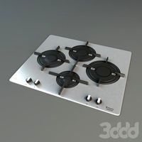
Gorenje GHS 64-ORA-W
...gorenje ghs 64-ora-w
3ddd
gorenje , варочная панель
варочная gorenje ghs 64-ora-w
turbosquid
$10

Dio D'Arte Mannelli E 1.1.7.200 GH
...el dio d'arte mannelli e 1.1.7.200 gh for download as max on turbosquid: 3d models for games, architecture, videos. (1336228)
turbosquid
$10
Dio D'Arte Mannelli E 1.1.5.200 GH
...el dio d'arte mannelli e 1.1.5.200 gh for download as max on turbosquid: 3d models for games, architecture, videos. (1308230)
3ddd
$1
ВАРОЧНАЯ ПОВЕРХНОСТЬ HOTPOINT-ARISTON 7HPK 644 D GH X /HA
... ariston
варочная поверхность hotpoint ariston 7hpk 644 d gh xha
габариты (шхг) 600 х 510 мм
68
3ddd
$1
Pillows 68
...pillows 68
3ddd
подушка
pillows 68. i hope you like it .thank you !
3ddd
$1
кресло G-68
...кресло g-68
3ddd
кресло
кресло руководителя g-68
3d_export
$50
Zp5 68
...zp5 68
3dexport
zp5 6.8
turbosquid
$20
Bath 68
... free 3d model bath 68 for download as max, dxf, fbx, and dwg on turbosquid: 3d models for games, architecture, videos. (1277107)
turbosquid
$39
HOUSE 68
... available on turbo squid, the world's leading provider of digital 3d models for visualization, films, television, and games.
turbosquid
$25
Ring 68
... available on turbo squid, the world's leading provider of digital 3d models for visualization, films, television, and games.
turbosquid
$22
Corbels 68
... available on turbo squid, the world's leading provider of digital 3d models for visualization, films, television, and games.
turbosquid
$20
Earrings 68
... available on turbo squid, the world's leading provider of digital 3d models for visualization, films, television, and games.
turbosquid
$9
Office 68
... available on turbo squid, the world's leading provider of digital 3d models for visualization, films, television, and games.
turbosquid
$2
chair - 68
... available on turbo squid, the world's leading provider of digital 3d models for visualization, films, television, and games.
Rgb
design_connected
$9
RGB
...rgb
designconnected
zero rgb pendant lights computer generated 3d model. designed by fredrik mattson.
3d_export
free
darts rgb
...darts rgb
3dexport
3d model darts rgb
3ddd
$1
RGB прожектор
...
rgb , прожектор
размеры
чёрный диаметр 25см высота 27см
хромовый диаметр 20см высота 25
turbosquid
$10
RGB Laptop
...squid
royalty free 3d model rgb laptop for download as blend on turbosquid: 3d models for games, architecture, videos. (1686573)
turbosquid
free
RGB Keyboard
...uid
free 3d model rgb keyboard for download as blend and obj on turbosquid: 3d models for games, architecture, videos. (1669677)
3d_export
free
rgb chair
...rgb chair
3dexport
turbosquid
$1

RGB Control
...free 3d model rgb control for download as 3ds, obj, and blend on turbosquid: 3d models for games, architecture, videos. (1257345)
turbosquid
$4
RGB Cabinet
...ee 3d model rgb cabinet for download as ma, fbx, obj, and stl on turbosquid: 3d models for games, architecture, videos. (1662943)
3ddd
$1

Сенсорный пульт RGB
... изменяемой итерацией. текстуры кнопок - одна растровая (сенсорный круг rgb), все остальные сделаны при помощи процедурных карт.
3ddd
free
Люстра Jar RGB
...люстра jar rgb
3ddd
jar
люстра jar rgb дизайнер арик леви
h-1500, d-460
Captured
turbosquid
$3

Captured Crystal Garden
...y free 3d model captured crystal garden for download as blend on turbosquid: 3d models for games, architecture, videos. (1343342)
3d_ocean
$89
Renault Captur 2014
...y, in real units of measurement, qualitatively and maximally close to the original. model formats: - *.max (3ds max 2008 scanl...
3d_export
$10
Mnb Capture 21 3D Model
...mnb capture 21 3d model
3dexport
mnb capture 21 3d model mnb 78412 3dexport
cg_studio
$99

Renault Captur concept3d model
...uto automotive prototype
.max - renault captur concept 3d model, royalty free license available, instant download after purchase.
3d_export
$99

Renault Captur 2014 3D Model
... 2016 crossover hatchback france french van minivan renault 2017 captur minisuv
renault captur 2014 3d model squir 66277 3dexport
cg_studio
$99

Renault Captur 20143d model
...o
.3ds .c4d .fbx .lwo .max .obj - renault captur 2014 3d model, royalty free license available, instant download after purchase.
turbosquid
$2

USB Capture Card SDI
... model usb capture card sdi for download as c4d, fbx, and obj on turbosquid: 3d models for games, architecture, videos. (1532257)
3d_export
$7
Capture costantini pietro 3D Model
... costantini pietro
capture costantini pietro 3d model download .c4d .max .obj .fbx .ma .lwo .3ds .3dm .stl makkey 110863 3dexport
cg_studio
$99

Renault Captur 20143d model
...3ds .c4d .fbx .lwo .max .mb .obj - renault captur 2014 3d model, royalty free license available, instant download after purchase.
3d_export
$99

Renault Captur 2014 3D Model
...014 2015 2016 5-door suv crossover concept electric sport eco france french
renault captur 2014 3d model humster3d 71689 3dexport
Keyboard
3d_ocean
$9
Keyboard
...odels computer electronics keyboard peripheral / part
computer keyboard 3d models. it’s computer keyboard. render ready keyboard.
archibase_planet
free
Keyboard
...keyboard
archibase planet
input keyboard keyboard office equipment
pro keyboard - 3d model for interior 3d visualization
3d_export
$5
keyboard
...keyboard
3dexport
computer keyboard
3d_export
$11
Keyboard
...keyboard
3dexport
gaming keyboard with backlight 1:1
3d_export
free
keyboard
...keyboard
3dexport
keyboard blender stl obj fbx
archibase_planet
free
Keyboard
...keyboard
archibase planet
keyboard pc equipment
keyboard apple n130315 - 3d model (*.gsm+*.3ds) for interior 3d visualization.
3d_export
free
keyboard gaming
...keyboard gaming
3dexport
keyboard gaming include: 1 x keyboard gaming.blend 3 x keyboard gaming.png
archibase_planet
free
Keyboard
...keyboard
archibase planet
keyboar pc equipment
keyboard - 3d model (*.gsm+*.3ds) for interior 3d visualization.
3d_ocean
$9

keyboard USB
...models computer electronics keyboard peripheral / part
keyboard for computer 3d models. high detailed model of computer keyboard.
turbosquid
$24

Keyboard
...urbosquid
royalty free 3d model keyboard for download as max on turbosquid: 3d models for games, architecture, videos. (1710291)
Lcd
turbosquid
$20

lcd
... available on turbo squid, the world's leading provider of digital 3d models for visualization, films, television, and games.
turbosquid
$15
LCD
... available on turbo squid, the world's leading provider of digital 3d models for visualization, films, television, and games.
turbosquid
$10
LCD
... available on turbo squid, the world's leading provider of digital 3d models for visualization, films, television, and games.
turbosquid
$10

LCD
... available on turbo squid, the world's leading provider of digital 3d models for visualization, films, television, and games.
turbosquid
$2

lcd
... available on turbo squid, the world's leading provider of digital 3d models for visualization, films, television, and games.
turbosquid
$1

lcd
... available on turbo squid, the world's leading provider of digital 3d models for visualization, films, television, and games.
turbosquid
free
lcd
... available on turbo squid, the world's leading provider of digital 3d models for visualization, films, television, and games.
turbosquid
free

LCD
... available on turbo squid, the world's leading provider of digital 3d models for visualization, films, television, and games.
3ddd
$1
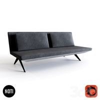
Noti Lcd Sofa
...noti lcd sofa
3ddd
noti , lcd
3d model of noti lcd sofa
3d_ocean
$7

Lcd tube wall
...hrome electronic electronic lcd tv videowall
lcd tube wall you can put in the lcd your own texture or movie in it and animate it.
Swap
3d_export
free
simple grass
...grass scene with procedural texture for grass, is better swap the texture of grass by...
3d_export
$12
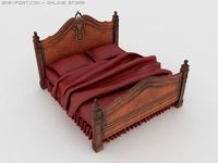
Classic bed_2 3D Model
...gregorian high quality good cheap classic bed_2 3d model swap 3233...
3d_export
$10
Classic bed 3D Model
...gregorian high quality good cheap classic bed 3d model swap 3232...
3d_export
$10
Classic bed_3 3D Model
...gregorian high quality good cheap classic bed_3 3d model swap 3234...
3ddd
$1

Комод bizzotto Iris art. 925
...которые установлены в multi/sub - object и меняются методом swap на первый id полигонов...
3d_ocean
$25
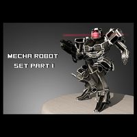
Mech Set #1
...this product features four modular parts that can be swaped out for other parts if...
3d_export
$30
spacecraft spaceship scifi
...good topology (polygon quad only) each material can be swaped or change normal and specular/glossyness texture included. available in...
3d_export
$30
spaceship scifi pbr realistic
...good topology (polygon quad only) each material can be swaped or change normal and specular/glossyness texture included. available in...
3ddd
$1

Прикроватная тумба bizzotto Voyage Prive art. 559
...во второй id multi/sub-object корпуса модели и меняется методом swap на первый...
3d_ocean
$12
Flip Video Camera
...screen image on the back that can easily be swaped out with your logo or whatever u want! two...
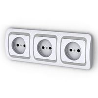
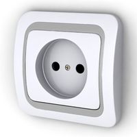
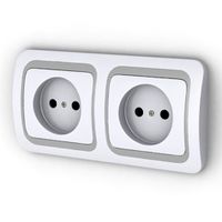
Sockets
archibase_planet
free
Socket
...socket
archibase planet
socket plug socket wall outlet
socket - 3d model (*.gsm+*.3ds) for interior 3d visualization.
archibase_planet
free
Socket
...socket
archibase planet
socket
socket - 3d model for interior 3d visualization.
archibase_planet
free
Socket
...socket
archibase planet
socket plug socket wall outlet
socket n210411 - 3d model (*.gsm+*.3ds) for interior 3d visualization.
archibase_planet
free
Socket
...socket
archibase planet
socket plug socket wall outlet
socket 1 - 3d model (*.gsm+*.3ds) for interior 3d visualization.
archibase_planet
free

Socket
...socket
archibase planet
socket plug socket wall outlet
socket 3 - 3d model (*.gsm+*.3ds) for interior 3d visualization.
archibase_planet
free
Socket
...socket
archibase planet
socket plug socket wall outlet
socket 4 - 3d model (*.gsm+*.3ds) for interior 3d visualization.
archibase_planet
free
Socket
...socket
archibase planet
socket plug socket wall outlet
socket 2 - 3d model (*.gsm+*.3ds) for interior 3d visualization.
archibase_planet
free
Socket
...socket
archibase planet
socket plug socket wall outlet
socket triple - 3d model (*.gsm+*.3ds) for interior 3d visualization.
archibase_planet
free
Socket
...socket
archibase planet
socket plug socket wall outlet
socket single - 3d model (*.gsm+*.3ds) for interior 3d visualization.
archibase_planet
free
Socket
...socket
archibase planet
socket plug socket wall outlet
socket twin - 3d model (*.gsm+*.3ds) for interior 3d visualization.
Hot
3d_export
$12
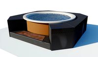
Hot Tub
...hot tub
3dexport
hot tub - 4k png/tif textures
3d_export
$9
Hot Tub
...hot tub
3dexport
hot tub - 4k png/tif textures
3d_export
free

hot chili
...hot chili
3dexport
hot chili<br>for fruits and getegables collection
3d_export
$5
hot air balloon
...hot air balloon
3dexport
hot air balloon
3d_export
free
Hot dog shop
...hot dog shop
3dexport
hot dog shop
turbosquid
$90
hot venue
...rbosquid
royalty free 3d model hot venue for download as fbx on turbosquid: 3d models for games, architecture, videos. (1336949)
turbosquid
$20

Hot Rod
...
turbosquid
royalty free 3d model hot rod for download as ma on turbosquid: 3d models for games, architecture, videos. (1351690)
turbosquid
$1

Hot dog
...turbosquid
royalty free 3d model hot dog for download as max on turbosquid: 3d models for games, architecture, videos. (1450961)
3d_ocean
$6
Hot-air Balloon
...alloon model created with 3ds max 2010 3 types of file format for you choose(.max .fbx .obj ) high detailed model without texture
3ddd
$1

Hot Rod by Baghera
...hot rod by baghera
3ddd
baghera , машинка
hot rod by baghera.
Key
archibase_planet
free
Key
...key
archibase planet
bunch of keys key
key n190510 - 3d model (*.gsm+*.3ds) for interior 3d visualization.
3d_export
$5
key
...key
3dexport
key
archibase_planet
free
Key
...key
archibase planet
key
key n080710 - 3d model (*.3ds) for interior 3d visualization.
3d_ocean
$2
Key
...key
3docean
door key lock open unlock
a key facecount: 617 (2x subsurfed: 9872)
archibase_planet
free

Key
...key
archibase planet
key
key n240713 - 3d model (*.gsm+*.3ds) for interior 3d visualization.
archibase_planet
free
Key
...key
archibase planet
key
key 2 n080710 - 3d model (*.gsm+*.3ds) for interior 3d visualization.
turbosquid
$3
Keys With Key Chain
... chain 3d model for download as blend, dae, stl, obj, and fbx on turbosquid: 3d models for games, architecture, videos. (1673644)
archibase_planet
free
Key
...key
archibase planet
key
key ancient strike plate n130912 - 3d model (*.3ds) for interior 3d visualization.
archibase_planet
free

Key
...key
archibase planet
key
key stephan mette n300412 - 3d model (*.gsm+*.3ds) for interior 3d visualization.
3d_export
free
key
...key
3dexport
a simple key obj, fbx, blend