Thingiverse
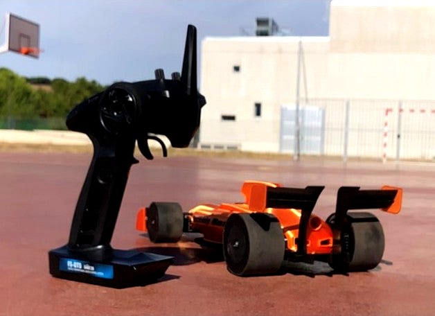
PERFORMANCE OPEN RC F1 CAR by Freerider4real
by Thingiverse
Last crawled date: 3 years, 3 months ago
PERFORMANCE OPEN RC F1 BUILD GUIDE
Note: Building procedure similar to original open RC f1. Also check Daniel Noree´s Youtube videos.
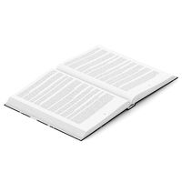
I will leave some photos so that you can reference and make the build easier.
Hardware: We are using the same bearings, electronics and bolts, but you will have to buy a pinion gear from amazon in order to avoid gear slippage.
https://www.amazon.es/Crazepony-UK-3-175mm-Pinion-Brushed-Brushless/dp/B07CK5K25S/ref=sr_1_fkmr0_1?__mk_es_ES=%C3%85M%C3%85%C5%BD%C3%95%C3%91&dchild=1&keywords=pinion+gear+1.175+shaft&qid=1598955523&sr=8-1-fkmr0
First Step: (bottom plates)
Printer settings: 40-50 infill, 2-3 perimeters, 0.28 layer height for more speed.
Trimmed edges reduce weight while permitting a wide variety of tire dimensions.
Second step: (Rear axle assembly)
Printer settings: 100% infill, 3 perimeters, 0.2 layer height.
Rear axle now has hexagonal ends for the rims to fit better. You MUST SAND THE AXLES before inserting rims, otherwise the rim will become locked in the axle. Use lubricant.
Cut a m3x12 bolt so that it becomes roughly a 10 mm threaded rod. Use epoxy glue an insert it into the holes in the axle. I also recommend epoxy for fixing the bearing in position.
To insert the pinion gear coupler, heat the 15t pinion gear from amazon with a lighter. Then press fit the plastic part into the metal gear in a perpendicular fashion. The teeth should mesh with the plastic. Make sure the gear is aligned properly.
Third step: (Steering mechanism)
Printer settings: 100% infill , 3 perimeters, 0.2 layer height.
Now the axle spins freely, independent form the wheel. The upper and lower boms are bigger to fit wider hubs for the new mechanism. There´s no need for a second bolt in the steering push pin.
Use m3*10 bolts to assemble the hubs to the upper and lower piece, but leave a gap (don’t fully tighten for free spinning).
IMPORTANT, please print upper and lower bom pieces with the outside part of the A-arm touching the build plate, so it has a smooth finish. Use epoxy glue to secure the bearings to the hubs. Insert the axles an apply epoxy to the inner part of the bearings, so the axle gets fixed on position.
Also you will need to insert a 10 mm m3 threaded rod into the axle similar to the rear axle procedure.
Use M312 bolts to secure the hubs to the push pins, and another m312 for securing the push pin. Use a clip for connecting the servo to the push pin. The servo must be secured to the bottom plate with hot glue.
Ensure the horn is perpendicular to the ground, so that the leverage is similar when turning right or left.
Fourth step: (bodywork)
Printer settings: 30-40% infill , 2 perimeters, 0.28 layer height.
EXCEPT: cap, vane right, vane left – 100% infill and lid – 20% infill
Just make sure to put extra hairspray on the build plate so that the piece doesn’t move while printing. Use m3*8 bolts except for the nose attaching to the front wing.
Lower infill on lid because it doesn´t handle any stress.
Fifth step (wings):
Printer settings: 100 % infill , 2-3 perimeters, 0.28 layer height.
Attach the front wing flaps to the front wing with epoxy to the side emplates. Also do the same for the 2 rear wings.
Sixth step (wheels):
Printer settings: 100 % infill , 3 perimeters, 0.28 layer height.
TPU tires: 15% infill , 1 perimeter, 0.28 layer height.
Closed rims for maximizing aero performance. Attach m3 nuts to secure the wheels in the axles.
You may use an extra layer of bicycle inner camera for more grip over the TPU tire.
If you can´t print TPU, use some kind of foam to wrap the rim, creating a cushion effect.
Note: Building procedure similar to original open RC f1. Also check Daniel Noree´s Youtube videos.
I will leave some photos so that you can reference and make the build easier.
Hardware: We are using the same bearings, electronics and bolts, but you will have to buy a pinion gear from amazon in order to avoid gear slippage.
https://www.amazon.es/Crazepony-UK-3-175mm-Pinion-Brushed-Brushless/dp/B07CK5K25S/ref=sr_1_fkmr0_1?__mk_es_ES=%C3%85M%C3%85%C5%BD%C3%95%C3%91&dchild=1&keywords=pinion+gear+1.175+shaft&qid=1598955523&sr=8-1-fkmr0
First Step: (bottom plates)
Printer settings: 40-50 infill, 2-3 perimeters, 0.28 layer height for more speed.
Trimmed edges reduce weight while permitting a wide variety of tire dimensions.
Second step: (Rear axle assembly)
Printer settings: 100% infill, 3 perimeters, 0.2 layer height.
Rear axle now has hexagonal ends for the rims to fit better. You MUST SAND THE AXLES before inserting rims, otherwise the rim will become locked in the axle. Use lubricant.
Cut a m3x12 bolt so that it becomes roughly a 10 mm threaded rod. Use epoxy glue an insert it into the holes in the axle. I also recommend epoxy for fixing the bearing in position.
To insert the pinion gear coupler, heat the 15t pinion gear from amazon with a lighter. Then press fit the plastic part into the metal gear in a perpendicular fashion. The teeth should mesh with the plastic. Make sure the gear is aligned properly.
Third step: (Steering mechanism)
Printer settings: 100% infill , 3 perimeters, 0.2 layer height.
Now the axle spins freely, independent form the wheel. The upper and lower boms are bigger to fit wider hubs for the new mechanism. There´s no need for a second bolt in the steering push pin.
Use m3*10 bolts to assemble the hubs to the upper and lower piece, but leave a gap (don’t fully tighten for free spinning).
IMPORTANT, please print upper and lower bom pieces with the outside part of the A-arm touching the build plate, so it has a smooth finish. Use epoxy glue to secure the bearings to the hubs. Insert the axles an apply epoxy to the inner part of the bearings, so the axle gets fixed on position.
Also you will need to insert a 10 mm m3 threaded rod into the axle similar to the rear axle procedure.
Use M312 bolts to secure the hubs to the push pins, and another m312 for securing the push pin. Use a clip for connecting the servo to the push pin. The servo must be secured to the bottom plate with hot glue.
Ensure the horn is perpendicular to the ground, so that the leverage is similar when turning right or left.
Fourth step: (bodywork)
Printer settings: 30-40% infill , 2 perimeters, 0.28 layer height.
EXCEPT: cap, vane right, vane left – 100% infill and lid – 20% infill
Just make sure to put extra hairspray on the build plate so that the piece doesn’t move while printing. Use m3*8 bolts except for the nose attaching to the front wing.
Lower infill on lid because it doesn´t handle any stress.
Fifth step (wings):
Printer settings: 100 % infill , 2-3 perimeters, 0.28 layer height.
Attach the front wing flaps to the front wing with epoxy to the side emplates. Also do the same for the 2 rear wings.
Sixth step (wheels):
Printer settings: 100 % infill , 3 perimeters, 0.28 layer height.
TPU tires: 15% infill , 1 perimeter, 0.28 layer height.
Closed rims for maximizing aero performance. Attach m3 nuts to secure the wheels in the axles.
You may use an extra layer of bicycle inner camera for more grip over the TPU tire.
If you can´t print TPU, use some kind of foam to wrap the rim, creating a cushion effect.
Similar models
thingiverse
free

Sport cub wing joiner by dooeydon
... apply allen wrench to m3 bolt head and begin tightening. when the m3 bolts are secure on the m3 nuts, the wing will be secure.
thingiverse
free

Snow Brush Pivot Head Repair by cedske
.... you can see if your printer is better and then glue them together. i used an extended pen spring to keep the switch pushed out.
thingiverse
free

Rear axle holder right and pinion gear for OpenRC Formula 1 car by LuisDUgena
...luisdugena
thingiverse
a modified version of the real axle holder (right) and pinion gear to fit propodrive 28-36s 2200kv motor.
thingiverse
free

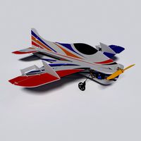
SkySword 70mm parts by s737500
...single perimeter, and 0 bottom, and 0 top layers, 0% infill.
i used spiral mode, as it does not create a seam, and prints faster.
thingiverse
free

Z40 gear for Universal-3 by Zvep
...perimeters = 25
external perimeters = 60%
infill = 30
solid infill = 40
top solid infill = 20
travel = 130
first layer speed = 20
thingiverse
free

Long Bolt for ball bearing filament holder by haylocki
....
in case you do not know how to change layer height during a print, i have provided a ready sliced bolt created using ideamaker.
thingiverse
free

Bicycle rear wing holder by yealexander
...nsert it into rear wing and rotate 90 degree. then screw it to bicycle.
best printed laying flat with 100% infill for durability.
thingiverse
free

Spinning Top by KasZap
...ayer height: 0.15 ; infill: 100%
no support is needed for any part if correct orientation is used, see print orientation picture.
thingiverse
free

Hubsan X4 H107L by Gogsi
...hubsan x4 h107l by gogsi
thingiverse
infill: 100%
layer height: 0.2mm
bottom piece: 4 perimeters
top piece: 4 perimeters
thingiverse
free

Prusa MK3 Feet for Earthquake Pads by astromech8037
...ent.
printed using the prusa pla filament in slic3r prusa edition. honeycomb 20% infill with 3 perimeters and .2 layer height.
F1
3d_export
free

f1
...f1
3dexport
model 3d f1
3d_export
$5

mercedes f1
...mercedes f1
3dexport
racing car mercedes f1
3ddd
$1

McLaren F1
...mclaren f1
3ddd
mclaren f1 без текстур.
3d_ocean
$25
RC F1
...rc f1
3docean
auto car control f1 formula race rc remote speed
remote control f1 car
3d_export
$7

f1 toy
...f1 toy
3dexport
this is a f1 car toy representative of mexcan artists.
3d_export
$15

f1 car mercedes
...f1 car mercedes
3dexport
f1 racing f1 car mercedes
3d_ocean
$19

F1 Tractor
...f1 tractor
3docean
f1 futuristic race tractor red tractor
simple futuristic race tractor model.
3d_ocean
$30

Formula F1
...ic f1 formula indianapolis indy luxury muscle race racer sedan sports street transport tuner vehicle
generic formula f1 race car.
3d_ocean
$50

McLaren F1
...uxury mc mclaren muscle race sedan sports street transport tuner vehicle
highly detailed exterior and interior of the mclaren f1.
turbosquid
$100

F1 Car
...
turbosquid
royalty free 3d model f1 car for download as obj on turbosquid: 3d models for games, architecture, videos. (1263925)
Rc
3ddd
$1
RC Helicopter
...rc helicopter
3ddd
вертолет
mini rc helicopter
93.329 polys
3d_export
$7
rc helicopter model
...rc helicopter model
3dexport
rc helicopter model
3d_ocean
$25
RC F1
...rc f1
3docean
auto car control f1 formula race rc remote speed
remote control f1 car
turbosquid
$10
rc plane
...lane
turbosquid
free 3d model rc plane for download as blend on turbosquid: 3d models for games, architecture, videos. (1295828)
turbosquid
$100
RC Helicopter
...free 3d model rc helicopter for download as 3ds, max, and obj on turbosquid: 3d models for games, architecture, videos. (1298511)
turbosquid
$59

Drone with RC
...3d model drone with rc for download as 3ds, max, obj, and fbx on turbosquid: 3d models for games, architecture, videos. (1363601)
turbosquid
$75
RC buggy
... available on turbo squid, the world's leading provider of digital 3d models for visualization, films, television, and games.
turbosquid
$39

RC Plane001
... available on turbo squid, the world's leading provider of digital 3d models for visualization, films, television, and games.
turbosquid
$30
RC Jet
... available on turbo squid, the world's leading provider of digital 3d models for visualization, films, television, and games.
turbosquid
$30
Rc airplane
... available on turbo squid, the world's leading provider of digital 3d models for visualization, films, television, and games.
Performance
turbosquid
$39

Perform Komers
...osquid
royalty free 3d model perform komers for download as on turbosquid: 3d models for games, architecture, videos. (1144652)
turbosquid
free

Performance Tire
...urbosquid
free 3d model performance tire for download as obj on turbosquid: 3d models for games, architecture, videos. (1485856)
3d_export
$17

F-18 Performance
...f-18 performance
3dexport
f-18 performance
turbosquid
$25

Performance Car Wheel
...model performance car wheel for download as max, obj, and fbx on turbosquid: 3d models for games, architecture, videos. (1241997)
turbosquid
$99

The Performer"s Stage
... available on turbo squid, the world's leading provider of digital 3d models for visualization, films, television, and games.
3d_export
$60

Jackson Performer 3D Model
...rformer instrument music musical steelplay band rock heavy metal floyd rose
jackson performer 3d model rendersteel 86884 3dexport
turbosquid
$2

Performance Tyres - set 1
... free 3d model performance tyres - set 1 for download as obj on turbosquid: 3d models for games, architecture, videos. (1691988)
turbosquid
$90

National Centre for the Performing Arts
...tre for the performing arts for download as max, obj, and fbx on turbosquid: 3d models for games, architecture, videos. (1262784)
turbosquid
$39

Movit Brakes High Performance
... available on turbo squid, the world's leading provider of digital 3d models for visualization, films, television, and games.
turbosquid
$5

Performance Tire Rim and Brakes
... available on turbo squid, the world's leading provider of digital 3d models for visualization, films, television, and games.
Open
3d_export
free
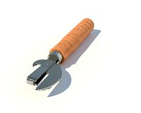
Opener
...r
3dexport
3d model of can opener. its my first work, if u can please show me my mistakes. this 3d model was created in autocad.
3d_export
free
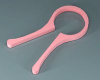
Cap opener
...cap opener
3dexport
handy cap opener, more files/formats here:
3ddd
$1
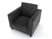
Кресло, Open Oreon.
...кресло, open oreon.
3ddd
open , oreon
кресло, open oreon.
3d_ocean
$4
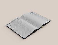
Open Book
...r interior max mental model open ray reading shelf text vray
open hardcover book with unique texture map on front and back cover.
turbosquid
$6
Opening Flag
...squid
royalty free 3d model opening flag for download as c4d on turbosquid: 3d models for games, architecture, videos. (1593555)
turbosquid
$10
Open book
...
royalty free 3d model open book for download as skp and obj on turbosquid: 3d models for games, architecture, videos. (1690781)
turbosquid
$2
bottle opener
...lty free 3d model bottle opener for download as blend and obj on turbosquid: 3d models for games, architecture, videos. (1621201)
turbosquid
$24

Bottle Opener
...free 3d model bottle opener for download as max, obj, and fbx on turbosquid: 3d models for games, architecture, videos. (1300948)
turbosquid
$20
Open Box
...yalty free 3d model open box for download as ma, obj, and fbx on turbosquid: 3d models for games, architecture, videos. (1481218)
turbosquid
$10
Wine Opener
...ty free 3d model wine opener for download as ma, obj, and fbx on turbosquid: 3d models for games, architecture, videos. (1240730)
Car
3d_export
$5

car
...car
3dexport
luxury car high quality car
3d_export
$5

car
...car
3dexport
luxury car high quality car
3d_export
$5

car
...car
3dexport
luxury car high quality car
3d_export
$5

car
...car
3dexport
luxury car high quality car
3d_export
$5
car
...car
3dexport
luxury car high quality car
archibase_planet
free
Car
...
archibase planet
car sports car motor-car sportster
car nascar#1 n300114 - 3d model (*.gsm+*.3ds) for exterior 3d visualization.
archibase_planet
free

Car
...ibase planet
car motor-car sportster sports car
car gablota xform n190214 - 3d model (*.gsm+*.3ds) for exterior 3d visualization.
archibase_planet
free
Car
...car
archibase planet
car motor car transport
car vaz 2104- 3d model for interior 3d visualization.
3d_export
$15

car
...car
3dexport
car
3d_export
free
car
...car
3dexport
car