Thingiverse
PCB & Schematics for Heliox LED dice
by Thingiverse
Last crawled date: 4 years, 1 month ago
Next more things.
Why limit us on counting to 6 only.
Change the game a bit, take 9!
New PCB (BETA) files
Possible outlines are 38x38mm and 40x40mm.
See the pics.
Proposal (BETA)
3x3 LED front face pcb layout
3x3 LED electronics circuit
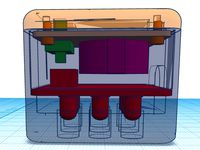
-some 3D redisign work needed on the top part
-requires changes on the firmware for using all LED's
-requires changes on the front to allow 9 LED, obviously
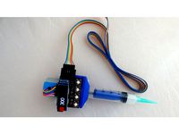
-requires mounting some parts on the copper side
See my first made pcb with the ATTiny soldered onto the copper side.
Take care on flipping or not the layout when printing for toner transfer method.
The DIP8 package must be oriented (pin1) as shown from the copper side this time.
..............
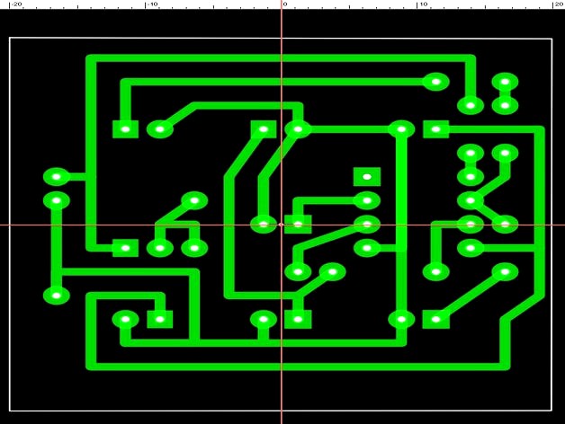
The electronically made copy of the blue print picture (pdf).
Here you are.
The exact hig resolution copy of the low res picture, recreated electronically.
AKA the Chineese Copy Cat Methode.
Did not know before how easy the copy cats can do their work with no effort.
Have it drawn line by line, dot by dot.
Positioning the frame centered was a little bit tricky.
Exported the graphic at 1200 dpi.
The picture size including the empty white area is 60x60mm.
.
No more Kiwi pcb files. See below.
The new version of the old pcb V2 is ready to print.
Have not produced the pcb by myself. could be done later on.
Not now.
See the preview shows it perfectly centered.
For those looking close up.
The red lines are made by the picture editor not the layout designer.
No problem here.
The files:
-Picture of my remix of the pcb seen on Heliox dice videos.
-The Schematics, I have improved for better reading, provided by KiwiGrinder.
Thx.https://thingiverse-production-new.s3.amazonaws.com/assets/85/55/9e/6f/cb/Schematic_SLP.jpg
-New old pcb v2 size 2*19.6mm on each side. Do the math ;-)
One layout picture has an extra wide brim for users using the toner transfer method.
It has a fat trace surrounding the outer shape lines of the design.
I know from own experience.
Think of all the users with the clothing irons, please.
It is not all High Tech all over the planet.
DL the zip-file. It has the design files.
.
The Heliox dice on Thingiversehttps://www.thingiverse.com/thing:2798081
Regardles of the flaws I have noticed, it looks good from the outside.
Merci.
.
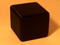
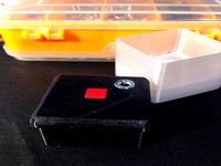
See a short video sequence of the black beauty.
Rename the "dice red on black.mp4.txt", by removing the .txt extension.
.
Nice find:
The most robust (mechanical wise) LED dice I have seen so far:
the Dutch Velleman PMK150 dice.
It gives a clue how things could be made from two pcb.
The standoff bolts give mechanical strength.
They serve as conductors too, replacing the needed 5 wires.
It has a great educational value for the DIY designer even if not build (copied) identically.
The PIC12C508A based dice designed by Dutch folks:https://files2.elv.com//public/10/1020/102036/Internet/102036_f02_plwuerfel_600x600.jpg
They have provided detailed build instructions and the schematics in the user manual printed on paper, for DL as pdf-file on the Velleman server.
But no software as usual.
It has the mechanical vibration detector (tube with balls), no toxic Mercury.
Conclusion:
Big value for the kids at home.
Great value for the money. This time it would be a good buy.
Some build videos can be found on YT.
iDoc has made one.
.
Something I'm missing on the pcb still.
-No reverse polarity protection
Add a diode , solder polarity opposed to the power over the power leads.
The cathode (the end with the ring marking) goes to the "+" pole.
-Have you put on a smoothing / filtering capacitor?
Every digitally working chip should have a smoothing capacitor, ca 33-100nF.
Can be made easily. Soldere one on the Vcc and ground pins of the ATTiny.
.
I'm busy making much more pleasing better design work.
Look here:https://www.thingiverse.com/thing:3926580
Have all parts drawn from scratch.
This is not the usual Chineese Copy Cats work,
the freeking me out, stupidly ignorant Steve Jobs complained about.
RIP, never come back, better go to hell.
The top bottom parts have mounting screw holes / standoffs.
Nothing will come loose or fall off easily.
For software development I have flipped the board.
Have the ATTiny on the top for easy removal.
I WANT THE SNAKE running, still.
.
Removed the Kiwi design files.
The reason.
His design might work if you are using lithographie.
but not with my cnc mill anf printing toner on pcb.
Thin traces between pin. Thin solder pads.
THE END
Why limit us on counting to 6 only.
Change the game a bit, take 9!
New PCB (BETA) files
Possible outlines are 38x38mm and 40x40mm.
See the pics.
Proposal (BETA)
3x3 LED front face pcb layout
3x3 LED electronics circuit
-some 3D redisign work needed on the top part
-requires changes on the firmware for using all LED's
-requires changes on the front to allow 9 LED, obviously
-requires mounting some parts on the copper side
See my first made pcb with the ATTiny soldered onto the copper side.
Take care on flipping or not the layout when printing for toner transfer method.
The DIP8 package must be oriented (pin1) as shown from the copper side this time.
..............
The electronically made copy of the blue print picture (pdf).
Here you are.
The exact hig resolution copy of the low res picture, recreated electronically.
AKA the Chineese Copy Cat Methode.
Did not know before how easy the copy cats can do their work with no effort.
Have it drawn line by line, dot by dot.
Positioning the frame centered was a little bit tricky.
Exported the graphic at 1200 dpi.
The picture size including the empty white area is 60x60mm.
.
No more Kiwi pcb files. See below.
The new version of the old pcb V2 is ready to print.
Have not produced the pcb by myself. could be done later on.
Not now.
See the preview shows it perfectly centered.
For those looking close up.
The red lines are made by the picture editor not the layout designer.
No problem here.
The files:
-Picture of my remix of the pcb seen on Heliox dice videos.
-The Schematics, I have improved for better reading, provided by KiwiGrinder.
Thx.https://thingiverse-production-new.s3.amazonaws.com/assets/85/55/9e/6f/cb/Schematic_SLP.jpg
-New old pcb v2 size 2*19.6mm on each side. Do the math ;-)
One layout picture has an extra wide brim for users using the toner transfer method.
It has a fat trace surrounding the outer shape lines of the design.
I know from own experience.
Think of all the users with the clothing irons, please.
It is not all High Tech all over the planet.
DL the zip-file. It has the design files.
.
The Heliox dice on Thingiversehttps://www.thingiverse.com/thing:2798081
Regardles of the flaws I have noticed, it looks good from the outside.
Merci.
.
See a short video sequence of the black beauty.
Rename the "dice red on black.mp4.txt", by removing the .txt extension.
.
Nice find:
The most robust (mechanical wise) LED dice I have seen so far:
the Dutch Velleman PMK150 dice.
It gives a clue how things could be made from two pcb.
The standoff bolts give mechanical strength.
They serve as conductors too, replacing the needed 5 wires.
It has a great educational value for the DIY designer even if not build (copied) identically.
The PIC12C508A based dice designed by Dutch folks:https://files2.elv.com//public/10/1020/102036/Internet/102036_f02_plwuerfel_600x600.jpg
They have provided detailed build instructions and the schematics in the user manual printed on paper, for DL as pdf-file on the Velleman server.
But no software as usual.
It has the mechanical vibration detector (tube with balls), no toxic Mercury.
Conclusion:
Big value for the kids at home.
Great value for the money. This time it would be a good buy.
Some build videos can be found on YT.
iDoc has made one.
.
Something I'm missing on the pcb still.
-No reverse polarity protection
Add a diode , solder polarity opposed to the power over the power leads.
The cathode (the end with the ring marking) goes to the "+" pole.
-Have you put on a smoothing / filtering capacitor?
Every digitally working chip should have a smoothing capacitor, ca 33-100nF.
Can be made easily. Soldere one on the Vcc and ground pins of the ATTiny.
.
I'm busy making much more pleasing better design work.
Look here:https://www.thingiverse.com/thing:3926580
Have all parts drawn from scratch.
This is not the usual Chineese Copy Cats work,
the freeking me out, stupidly ignorant Steve Jobs complained about.
RIP, never come back, better go to hell.
The top bottom parts have mounting screw holes / standoffs.
Nothing will come loose or fall off easily.
For software development I have flipped the board.
Have the ATTiny on the top for easy removal.
I WANT THE SNAKE running, still.
.
Removed the Kiwi design files.
The reason.
His design might work if you are using lithographie.
but not with my cnc mill anf printing toner on pcb.
Thin traces between pin. Thin solder pads.
THE END
Similar models
thingiverse
free
3x3 LED Heliox cube remix collection
...iverse.com/thing:3926580
heliox arduino code.
arduino attiny85/45 support file (basically it is a link for the boardmanager only)
thingiverse
free

Arduino 328P Voltmeter Soldering Kit PCB remake by makibox850
.../www.venatormfg.com/voltmeter-solder-kit-instructions.html
hint
advanced methods reverse engineering a pcb
yt video v=dq9mh9bbyp0
thingiverse
free

Art Deco FM Radio with PCB
... connection pin on the encoder pin header . the updated eagle files have a four pin header which includes a connection to ground.
3dwarehouse
free

VTSS5 Velleman Soldering Iron
...ave one and it works very well. please rate!!! #50 #iron #kb1udn #solder #soldering #variable_temperature #velleman #vtss5 #watts
thingiverse
free

PCB Christmas Tree
...ark board and uploaded the sketch (also included). i tested the tree and once it was working, soldered the attiny85 onto the pcb.
grabcad
free

Quadcopter project
...t is hard to notice. but all these are solvable once we have more experience on pcb design, like math problems, do more practice.
thingiverse
free
Solder Paste Dispenser
...oshpark, and these are the components as a shared project at mouser. and here are zipped gerbers for pcb manufacturing at jlcpcb.
thingiverse
free
LED cube 29mm standard dice edition
...system.https://www.thingiverse.com/thing:3926580 the cube size is 29mm. there is a similar cube thing i have designed and adopted to fit...
thingiverse
free

Velleman K8200 3D printer - LED ring light by ljwinkler
..., part list can be found on my blog: http://ljwinkler.blogspot.com/2014/02/led-ring-light-for-velleman-k8200-3d.html
cheers,
lj
thingiverse
free

PCB Milling Machine by mediamilan
...tps://www.youtube.com/watch?v=fvvjuva_jis
https://www.youtube.com/watch?v=x6-dlpdx3hq
https://www.youtube.com/watch?v=nmztaahrn0i
Heliox
3d_sky
free

HELIOX Wizard Chair
...heliox wizard chair
3dsky
the wizard chair heliox (a plastic chair on casters)
thingiverse
free

Cale d'alignement Lampe Pixel heliox by MoogyFR
...ccueillant les bandeaux led de la lampe pixel d'heliox. je cherchais un moyen pour que la lumière soit parfaitement diffusée.
thingiverse
free

Usb Tower remix from Heliox by JLo75
...usb tower remix from heliox by jlo75
thingiverse
ajout d'un pied et de trous pour des stylos/stylets
thingiverse
free
3x3 LED Heliox cube remix collection
...iverse.com/thing:3926580
heliox arduino code.
arduino attiny85/45 support file (basically it is a link for the boardmanager only)
thingiverse
free

Mini Poubelle by Heliox by HelioxLab
...e pour jeter les chutes de filaments !
je vous la présente dans cette video : https://youtu.be/o1vvmmpp2p4 (english : go to 4:00)
thingiverse
free

pliers stand / support de pinces by Heliox by HelioxLab
...by heliox by helioxlab
thingiverse
support pour pinces présenté dans la vidéo :https://youtu.be/tamhd__nslk (english go to 5:30)
thingiverse
free

Lampe articulée Heliox Plateau leds 90C° by FlyManou
...ps://cults3d.com/fr/mod%c3%a8le-3d/maison/lampe-articulee-avec-video-explicative with 90 ° rotation of the led support plate.
@ +
thingiverse
free

Cale d'alignement leds lampe Heliox by herka57
...j'ai fait également une petite cale / un gabarit pour avoir le bon espacement des bandelettes led pour les souder facilement.
thingiverse
free

Le labo d'Heliox - logo by Samfire54
...le labo d'heliox - logo by samfire54
thingiverse
heliox logo, made with love^^
thingiverse
free
LED dice bottom Heliox remix
...amp;k, 25 years back in time.
now tey have a similar looking ks series.https://www.ckswitches.com/products/keyswitch/ks/
the end
Schematics
turbosquid
$54

Logic Schematic Symbol Collection
... available on turbo squid, the world's leading provider of digital 3d models for visualization, films, television, and games.
3d_export
$39
Logic Schematic Symbol Collection 3D Model
...or amplifier inverter cob 3ds obj dxf directx visualmotion
logic schematic symbol collection 3d model visualmotion 79452 3dexport
3d_ocean
$17
Schematic city
...oon square cartoon street cartoon town city map road square street town
cartoon low-poly city, a simple model that is easy to use
3d_export
free
set of schematic vessels 3 pieces
..., fbx<br>- count of vertexes : 666000<br>- count of faces:651000<br>https://www.youtube.com/watch?v=nfmnprp0ese
3d_ocean
$10

DNA Model
...dna model
3docean
array dna genes health hi-poly hipoly hospital medicine schematic small
part of dna , schematic
3d_export
$7

Gas burner
...gas burner
3dexport
schematic model of the gas burner weishaupt g30 for boilers heating and hot water supply
3d_export
$10

samsung galaxy s21 ultra 5g
...<br>. this model was precisely created accordingly to the schematics ...
3d_export
$10

samsung galaxy s21 5g
...s21. it has been modeled precisely according to the schematics ...
3d_export
$30
Wind Turbine 3D Model
... alternative electric energy power renewable eco green generator interior schematic
wind turbine 3d model blacks3d 18897 3dexport
3d_export
$26

Oil chart
...olygons (3ds max file): 517 050. quantity of vertex: 585 078. version of the program: 3ds max 2018. type of render: coronarender.
Dice
3d_export
$5

dice
...dice
3dexport
dice geometry
3d_export
$5

Dice
...dice
3dexport
a dice for poker
3d_ocean
$4
Dices
...dices
3docean
dice dices
this was created 3ds max 2014. file contains obj, 3ds, max, fbs file types.
3ddd
$1
dice+
...tic dice on electronic devices, in addition to technology.
everything made in 3ds max + vray blend material with light number.
3d_ocean
$2
dice
...dice
3docean
3ds arman3dg dice games low max poly
dice [2 texture color 512-128, 1024-256] (3ds max file- 2010, 2011, 2012)
turbosquid
free
Dice
...dice
turbosquid
free 3d model dice for download as obj on turbosquid: 3d models for games, architecture, videos. (1310801)
turbosquid
free

Dice
...dice
turbosquid
free 3d model dice for download as blend on turbosquid: 3d models for games, architecture, videos. (1250342)
turbosquid
free

Dice
...dice
turbosquid
free 3d model dice for download as blend on turbosquid: 3d models for games, architecture, videos. (1393051)
3d_export
$5

rol dice
...rol dice
3dexport
rol dices
3d_ocean
$3
Dice+Cards
...dice+cards
3docean
dice+cards
Pcb
3ddd
$1
GRAMERCY HOME - CARMELA ARMCHAIR 602.023-PCB
...gramercy home - carmela armchair 602.023-pcb
3ddd
gramercy home
gramercy home
carmela armchair
602.023-pcb
www.gramercy-home.ru
3d_export
$150
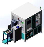
auto pcb board loder inspection machine
...auto pcb board loder inspection machine
3dexport
auto pcb board loder & inspection machine --> only step file
3d_export
$7
turning mechanism drawing pcb board turnover machine
...turning mechanism drawing pcb board turnover machine
3dexport
turning mechanism drawing pcb board turnover machine
turbosquid
$9

Stereo Jack 3.5mm for soldering to a PCB
... available on turbo squid, the world's leading provider of digital 3d models for visualization, films, television, and games.
3d_export
$5
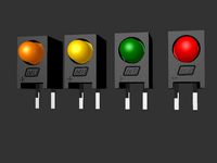
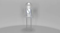
LED Right Angled PCB Mounting
...m led. step and igus files. multiple led colors: blue, purple, red, green, and yellow. dimensions case w 4,5mm , h 7,3mm l 6,4mm.
3d_export
$20
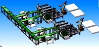
automatic pcb loading and unloading dispensing test automatic line
...ment structure is very complex. it is a very practical equipment for smt industry. the equipment is mature application equipment.
3d_export
$18
an automatic line for fct function test of pcb
... drawings are downloaded, you can directly watch and edit the contents. welcome to download and learn from your favorite friends.
3d_export
$5
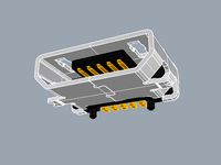
USB Micro B connector
...step and igus for 3d import into ecad tools, pcb footprints. added also a altium designer pcb component library...
3d_export
$15
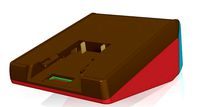
plastic housing with dewalt battery holder
...case measures 155x106x60. inside the case there are two pcb of 130x98 and 98x42...
3d_export
$7
automatic packing line - packing sorting and stacking equipment line
...sorting and stacking equipment line 3dexport automatic packaging line<br>1. pcb board is manually placed from the placement position and...
Led
3d_export
$5
led
...led
3dexport
the led is cut with all the parts.
3ddd
$1
Monacor / PARL56DMX / LED-320RGBW / LED-345RGBW / LED-300RGB
... прожектор
http://www.monacor.dk/
parl56dmx
led-320rgbw
led-345rgbw
led-300rgb
turbosquid
$10
LED
...led
turbosquid
free 3d model led for download as blend on turbosquid: 3d models for games, architecture, videos. (1691856)
3d_export
$5

led lamp
...led lamp
3dexport
led lamp, brightness animation
3ddd
free
leds-c4
...leds-c4
3ddd
leds-c4
современный торшер
3ddd
free
leds-c4
...leds-c4
3ddd
leds-c4
настольный лампа
turbosquid
$19

LED
... available on turbo squid, the world's leading provider of digital 3d models for visualization, films, television, and games.
turbosquid
$12
Led
... available on turbo squid, the world's leading provider of digital 3d models for visualization, films, television, and games.
turbosquid
free
LED
... available on turbo squid, the world's leading provider of digital 3d models for visualization, films, television, and games.
turbosquid
free

LED
... available on turbo squid, the world's leading provider of digital 3d models for visualization, films, television, and games.