Thingiverse
PC Racing Handbrake and Button Box by Roedkill
by Thingiverse
Last crawled date: 3 years ago
EDIT 3/26/17 - Wrong version of base.stl was uploaded, and some parts were in the wrong orientation for printing. Correct versions are now available.
I wanted to upgrade the old handbrake setup with a custom analog handbrake and button box. Instead of using a simple switch for the signal, it uses a rotary potentiometer to be a bit more realistic. I used a Teensy 3.2 to read the signals and send them to the PC over USB. You can use the handbrake as a standalone unit without the button box, but you will have to make an enclosure for the Teensy and wiring.
Tools
Dremel or sandpaper
Drill
Socket/wrench for M6 bolts/nuts
2mm hex driver for M3 screws
Parts List
(1) Teensy 3.2: https://www.sparkfun.com/products/13736
(2) Teensy Header Kit: https://www.sparkfun.com/products/13925
(1) Rotary Potentiometer - 10k Ohm, Linear: https://www.sparkfun.com/products/9939
(1) USB microB Cable - 6 Foot: https://www.sparkfun.com/products/10215
(16) Cherry MX Switch: https://www.sparkfun.com/products/13834
(1) 5pcs 6x8cm Double-side Prototype PCB Universal Printed Circuit Board: https://www.amazon.com/gp/product/B0147YM3DG/ref=oh_aui_detailpage_o06_s01?ie=UTF8&psc=1
(1) 8mm Shaft 150mm Linear Motion Rod: I had a spare one of these from my printer. I could not find a 150mm length rod, but here is a 10in version: https://www.vxb.com/8mm-Shaft-10-Hardened-Rod-Linear-Motion-p/kit14127.htm
(1-3) Springs (I used 3): https://www.menards.com/main/tools-hardware/fasteners-fastener-accessories/specialty-fasteners/springs/1-4-x-2-7-16-x-032-wg-extension-springs-1-pcs/p-1444440208368-c-9553.htm?tid=-9060762992386579289
Wire: I used wire from an old ethernet cable
(1) Styrene Sheet Plastruct sss-108 (used for front and rear cover of button box): https://www.amazon.com/Plastruct-PLS91106-SSS-108-White-Styrene/dp/B0000WS9WY/ref=sr_1_1?ie=UTF8&qid=1490499076&sr=8-1
(4) M6x1.0 Bolts (length should be approximately thickness of your mounting surface plus 15mm): http://www.homedepot.com/p/Everbilt-M6-1-0-x-35-mm-Zinc-Plated-Steel-Hex-Bolt-2-per-Bag-802578/204281412
(4) M6x1.0 Nuts: http://www.homedepot.com/p/Crown-Bolt-M6-ZINC-METRIC-HEX-NUT-10-9-5-Pieces-40678/202836255
(4) M6 Washers: http://www.homedepot.com/p/M6-Zinc-Plated-Flat-Washers-4-Piece-803548/204276430
M3 Screws: https://www.amazon.com/Dophee-120Pcs-Button-Stainless-Assortment/dp/B01A6T70IE/ref=sr_1_1?ie=UTF8&qid=1490499861&sr=8-1
Optional Parts
(1) Toggle Switch: Any 2 position toggle switch will work. Ex: https://www.sparkfun.com/products/9276
(1) uxcell 10 Pcs 2.54mm Pitch 4 Pins DIP Mounting Photo Coupler PC817: https://www.amazon.com/gp/product/B00S4YRMB4/ref=od_aui_detailpages00?ie=UTF8&psc=1
(1) 1K ohm resistor: https://www.sparkfun.com/products/13760
(1) JST Connector pair (you can use any 2 pin connector here, or solder the wires instead): https://www.amazon.com/Electop-Connector-Wire-Cable-100mm/dp/B01LN0XE94/ref=sr_1_7?s=electronics&ie=UTF8&qid=1490497893&sr=1-7&keywords=jst+connector+pair
The toggle switch is used to add some functionality. Some games do not support an analog signal for the handbrake, so the switch is setup to switch from analog mode to digital mode, which will simulate a button press when you pull the handbrake past a certain threshold. Some games only support one controller/joystick at a time, so I added the PC817 photo coupler and resistor to send the signal to my G27 wheel, which simulates a button press on the G27 wheel. The JST connector is between the button box and G27 shifter so I can separate them if needed.
Wiring
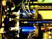
Handbrake: Only three wires are needed for functionality of the handbrake. Gound and Positive are soldered to the outside pins on the potentiometer, and the analog signal wire is soldered to the center pin. It does not matter which pin is ground or positive.
Buttons: All buttons have one pin connected to ground, and the other to various digital input pins on the Teensy.
Toggle Switch: One pin to ground, and the other to a digital input pin.
PC817: Data Sheet: http://www.farnell.com/datasheets/73758.pdf
Pin 1: 1K resistor connected to Teensy pin
Pin 2: Teensy Ground
Pin 3: JST Connector Ground (Black)
Pin 4: JST Connector Positive (Red)
The JST connector is wired to where the 2 wires that connected to the limit switch in my old setup here: http://www.thingiverse.com/thing:646368
Im not sure if this was necessary, but I did power on the wheel and test which wire was positive and negative with a multimeter. The red JST connector wire was soldered to the wire with +5 volts and the G27 shifter, and the other wire soldered to ground.
Teensy:
One set of the header kit is soldered to the PCB, and the other is soldered to the Teensy. This allows you to remove the board easily if needed. The final pinout for the board is shown below. It is probably not the most efficient way to wire everything, but it works. If you make changes here, you will have to change to code.
Referencing this diagram: https://cdn.sparkfun.com/datasheets/Dev/Arduino/Boards/card7a_rev1.pdf
GND: Common ground between all buttons, toggle switch, and PC817 (Pin 2)
Pin 0: Button 1 Signal Wire
Pin 1: Button 2 Signal Wire
Pin 2: Button 3 Signal Wire
Pin 3: Button 4 Signal Wire
Pin 4: Button 5 Signal Wire
Pin 5: Button 6 Signal Wire
Pin 6: Button 7 Signal Wire
Pin 7: Button 8 Signal Wire
Pin 8: Button 9 Signal Wire
Vin:
AGND: Handbrake Gound (Pin 1 or 3 on the potentiometer)
3.3V: Handbrake Positive (Pin 1 or 3 on the potentiometer)
Pin 23: Handbrake Signal (Pin 2 on the potentiometer)
Pin 20: Button 16 Signal Wire
Pin 19: Button 15 Signal Wire
Pin 18: Button 14 Signal Wire
Pin 17: Button 13 Signal Wire
Pin 16: Button 12 Signal Wire
Pin 15: Button 11 Signal Wire
Pin 14: Button 10 Signal Wire
Code Setup
First follow the instructions here to install the required software: https://www.pjrc.com/teensy/td_download.html
You will need to change the "USB Type" to "Keyboard + Mouse + Joystick" which is shown here: https://www.pjrc.com/teensy/teensyduino.html
Open up the Button_Box_and_Handbrake.ino file, and upload it to your Teensy.
You can open the serial monitor to make sure the signals are working.
To make sure windows is getting inputs from the Teensy, follow instructions here to open joy.cpl and view inputs: https://www.pjrc.com/teensy/td_joystick.html
After you upload the code to the Teensy, all you have to do in the future is plug in the USB to your computer and it will show up as a joystick. Cycle the handbrake at least once after you plug it in to automatically calibrate the endpoints. If you need to re-calibrate, while you are using it, press buttons 1, 7, 10, and 16 (the four corners) at the same time, and cycle the handbrake. I have never had to do this since it re-calibrates every time you plug it in, but I thought it would be a nice feature if it was ever necessary. The toggle switch will alternate between digital and analog mode. I leave mine in analog mode unless the game does not support it.
Assembly
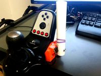
Detailed pictures will be added if there is enough interest
Handbrake
Printed Parts List:
(1) Base
(1) Base Cover
(1) Handle
(1) Potentiometer Mount
(1) Potentiometer Cover
(1) Handle Mount
Sand the round sections of "Base," "Base Cover," and "Handle Mount" parts until the parts don't bind.
Make sure the M6 bolts slide freely through the holes in the bottom of the "Base." If they don't move freely, drill out the holes slightly larger.
Glue 2 of the M6 nuts into the hex holes in the bottom of the "Base" using a small amount of super glue.
Attach the potentiometer to the "Potentiometer Mount" using the nut and washer it comes with. You may have to drill out this hole.
Make sure the spinning part of the potentiometer fits in the side hole of the "Handle Mount." This should be a tight enough fit that the potentiometer does not slip inside the hole while in use.
Insert the 8mmx150mm Rod into the "Handle." This will be a very tight fit. I have found the best way to do this is to put the rod in a drill and drill the rod into the part.
Remove the rod, and repeat the process in the previous step with the "Handle Mount."
Slide the rod into the slot on of the "Base Cover," and re-attach the Handle to the other end. You can use an M3 screw as set screw to hold the rod in place, but I found this was not necessary.
Using M3 screws, screw one end of each of your springs into the bottom of the "Handle Mount."
Using M3 screws, screw the other end of each spring into the "Base."
Using 4 M3 screws, attach the "Base Cover" to the "Base," and make sure everything is moving freely.
Rotate your potentiometer to the approximate center position, and attach it to the side of the "Base" using 2 M3 Screws.
Slide 3 wires through the hole in the back of the "Base" and solder them to the potentiometer.
Attach the "Potentiometer Cover" using 2 M3 Screws.
Solder the other ends of the potentiometer wires to Teensy. You can also add your own 3 pin connector here instead of hard wiring to the Teensy.
Bolt the assembly to your mounting surface using 2 M6 bolts.
Button Box
Printed Parts List:
(2) pcb mount
(4) spacer
(1) Button
(1) box
(2) Button Cover
(1) Rear PCB Mount OR Rear PCB Mount 1 Piece
Optional mounting brackets:
(1) Bolt Mount
(2) Bolt Mount2
I used the Rear PCB Mount which only covers the middle section on the back of the button box. The front faceplate and gaps on either side of the back were made with the styrene sheets. The wiring was made up as I went, but I started with mounting the Cherry MX Switches to the PCBs by drilling out many holes. I then soldered the Teensy headers to the center PCB, and secured the PCBs together using the "pcb mount," "spacer," and some M3 screws. This is a good place in the assembly to finish the wiring and upload the code to make sure everything works as intended. Screw the "Rear PCB Mount" into the "pcb mounts," and then into the "Box." Make your faceplate and rear covers using the "Box" as a template. I used a sheet of paper, and punched a screwdriver through each of the holes to make a drilling template. I cut out 2 rectangular holes using a dremel and cutoff wheel that are just big enough for each group of 8 buttons. Start with a small hole, and make adjustments until everything fits. Once you have the faceplate on, start sanding the insides of the "Button Covers" until they fit over one group of buttons. I originally intended to use screws to attach the "Button Covers" to the faceplate, but it wasn't easy to line up perfectly to drill holes, so I just used some superglue at each corner instead. The mounting brackets are attached with screws, and M6 nuts are glued into the hex holes on the "Bolt Mount" part to mount the box to a flat surface.
I think I have covered just about every step of the assembly process, but I probably missed some things. Feel free to ask questions if I need to clarify anything.
I wanted to upgrade the old handbrake setup with a custom analog handbrake and button box. Instead of using a simple switch for the signal, it uses a rotary potentiometer to be a bit more realistic. I used a Teensy 3.2 to read the signals and send them to the PC over USB. You can use the handbrake as a standalone unit without the button box, but you will have to make an enclosure for the Teensy and wiring.
Tools
Dremel or sandpaper
Drill
Socket/wrench for M6 bolts/nuts
2mm hex driver for M3 screws
Parts List
(1) Teensy 3.2: https://www.sparkfun.com/products/13736
(2) Teensy Header Kit: https://www.sparkfun.com/products/13925
(1) Rotary Potentiometer - 10k Ohm, Linear: https://www.sparkfun.com/products/9939
(1) USB microB Cable - 6 Foot: https://www.sparkfun.com/products/10215
(16) Cherry MX Switch: https://www.sparkfun.com/products/13834
(1) 5pcs 6x8cm Double-side Prototype PCB Universal Printed Circuit Board: https://www.amazon.com/gp/product/B0147YM3DG/ref=oh_aui_detailpage_o06_s01?ie=UTF8&psc=1
(1) 8mm Shaft 150mm Linear Motion Rod: I had a spare one of these from my printer. I could not find a 150mm length rod, but here is a 10in version: https://www.vxb.com/8mm-Shaft-10-Hardened-Rod-Linear-Motion-p/kit14127.htm
(1-3) Springs (I used 3): https://www.menards.com/main/tools-hardware/fasteners-fastener-accessories/specialty-fasteners/springs/1-4-x-2-7-16-x-032-wg-extension-springs-1-pcs/p-1444440208368-c-9553.htm?tid=-9060762992386579289
Wire: I used wire from an old ethernet cable
(1) Styrene Sheet Plastruct sss-108 (used for front and rear cover of button box): https://www.amazon.com/Plastruct-PLS91106-SSS-108-White-Styrene/dp/B0000WS9WY/ref=sr_1_1?ie=UTF8&qid=1490499076&sr=8-1
(4) M6x1.0 Bolts (length should be approximately thickness of your mounting surface plus 15mm): http://www.homedepot.com/p/Everbilt-M6-1-0-x-35-mm-Zinc-Plated-Steel-Hex-Bolt-2-per-Bag-802578/204281412
(4) M6x1.0 Nuts: http://www.homedepot.com/p/Crown-Bolt-M6-ZINC-METRIC-HEX-NUT-10-9-5-Pieces-40678/202836255
(4) M6 Washers: http://www.homedepot.com/p/M6-Zinc-Plated-Flat-Washers-4-Piece-803548/204276430
M3 Screws: https://www.amazon.com/Dophee-120Pcs-Button-Stainless-Assortment/dp/B01A6T70IE/ref=sr_1_1?ie=UTF8&qid=1490499861&sr=8-1
Optional Parts
(1) Toggle Switch: Any 2 position toggle switch will work. Ex: https://www.sparkfun.com/products/9276
(1) uxcell 10 Pcs 2.54mm Pitch 4 Pins DIP Mounting Photo Coupler PC817: https://www.amazon.com/gp/product/B00S4YRMB4/ref=od_aui_detailpages00?ie=UTF8&psc=1
(1) 1K ohm resistor: https://www.sparkfun.com/products/13760
(1) JST Connector pair (you can use any 2 pin connector here, or solder the wires instead): https://www.amazon.com/Electop-Connector-Wire-Cable-100mm/dp/B01LN0XE94/ref=sr_1_7?s=electronics&ie=UTF8&qid=1490497893&sr=1-7&keywords=jst+connector+pair
The toggle switch is used to add some functionality. Some games do not support an analog signal for the handbrake, so the switch is setup to switch from analog mode to digital mode, which will simulate a button press when you pull the handbrake past a certain threshold. Some games only support one controller/joystick at a time, so I added the PC817 photo coupler and resistor to send the signal to my G27 wheel, which simulates a button press on the G27 wheel. The JST connector is between the button box and G27 shifter so I can separate them if needed.
Wiring
Handbrake: Only three wires are needed for functionality of the handbrake. Gound and Positive are soldered to the outside pins on the potentiometer, and the analog signal wire is soldered to the center pin. It does not matter which pin is ground or positive.
Buttons: All buttons have one pin connected to ground, and the other to various digital input pins on the Teensy.
Toggle Switch: One pin to ground, and the other to a digital input pin.
PC817: Data Sheet: http://www.farnell.com/datasheets/73758.pdf
Pin 1: 1K resistor connected to Teensy pin
Pin 2: Teensy Ground
Pin 3: JST Connector Ground (Black)
Pin 4: JST Connector Positive (Red)
The JST connector is wired to where the 2 wires that connected to the limit switch in my old setup here: http://www.thingiverse.com/thing:646368
Im not sure if this was necessary, but I did power on the wheel and test which wire was positive and negative with a multimeter. The red JST connector wire was soldered to the wire with +5 volts and the G27 shifter, and the other wire soldered to ground.
Teensy:
One set of the header kit is soldered to the PCB, and the other is soldered to the Teensy. This allows you to remove the board easily if needed. The final pinout for the board is shown below. It is probably not the most efficient way to wire everything, but it works. If you make changes here, you will have to change to code.
Referencing this diagram: https://cdn.sparkfun.com/datasheets/Dev/Arduino/Boards/card7a_rev1.pdf
GND: Common ground between all buttons, toggle switch, and PC817 (Pin 2)
Pin 0: Button 1 Signal Wire
Pin 1: Button 2 Signal Wire
Pin 2: Button 3 Signal Wire
Pin 3: Button 4 Signal Wire
Pin 4: Button 5 Signal Wire
Pin 5: Button 6 Signal Wire
Pin 6: Button 7 Signal Wire
Pin 7: Button 8 Signal Wire
Pin 8: Button 9 Signal Wire
Vin:
AGND: Handbrake Gound (Pin 1 or 3 on the potentiometer)
3.3V: Handbrake Positive (Pin 1 or 3 on the potentiometer)
Pin 23: Handbrake Signal (Pin 2 on the potentiometer)
Pin 20: Button 16 Signal Wire
Pin 19: Button 15 Signal Wire
Pin 18: Button 14 Signal Wire
Pin 17: Button 13 Signal Wire
Pin 16: Button 12 Signal Wire
Pin 15: Button 11 Signal Wire
Pin 14: Button 10 Signal Wire
Code Setup
First follow the instructions here to install the required software: https://www.pjrc.com/teensy/td_download.html
You will need to change the "USB Type" to "Keyboard + Mouse + Joystick" which is shown here: https://www.pjrc.com/teensy/teensyduino.html
Open up the Button_Box_and_Handbrake.ino file, and upload it to your Teensy.
You can open the serial monitor to make sure the signals are working.
To make sure windows is getting inputs from the Teensy, follow instructions here to open joy.cpl and view inputs: https://www.pjrc.com/teensy/td_joystick.html
After you upload the code to the Teensy, all you have to do in the future is plug in the USB to your computer and it will show up as a joystick. Cycle the handbrake at least once after you plug it in to automatically calibrate the endpoints. If you need to re-calibrate, while you are using it, press buttons 1, 7, 10, and 16 (the four corners) at the same time, and cycle the handbrake. I have never had to do this since it re-calibrates every time you plug it in, but I thought it would be a nice feature if it was ever necessary. The toggle switch will alternate between digital and analog mode. I leave mine in analog mode unless the game does not support it.
Assembly
Detailed pictures will be added if there is enough interest
Handbrake
Printed Parts List:
(1) Base
(1) Base Cover
(1) Handle
(1) Potentiometer Mount
(1) Potentiometer Cover
(1) Handle Mount
Sand the round sections of "Base," "Base Cover," and "Handle Mount" parts until the parts don't bind.
Make sure the M6 bolts slide freely through the holes in the bottom of the "Base." If they don't move freely, drill out the holes slightly larger.
Glue 2 of the M6 nuts into the hex holes in the bottom of the "Base" using a small amount of super glue.
Attach the potentiometer to the "Potentiometer Mount" using the nut and washer it comes with. You may have to drill out this hole.
Make sure the spinning part of the potentiometer fits in the side hole of the "Handle Mount." This should be a tight enough fit that the potentiometer does not slip inside the hole while in use.
Insert the 8mmx150mm Rod into the "Handle." This will be a very tight fit. I have found the best way to do this is to put the rod in a drill and drill the rod into the part.
Remove the rod, and repeat the process in the previous step with the "Handle Mount."
Slide the rod into the slot on of the "Base Cover," and re-attach the Handle to the other end. You can use an M3 screw as set screw to hold the rod in place, but I found this was not necessary.
Using M3 screws, screw one end of each of your springs into the bottom of the "Handle Mount."
Using M3 screws, screw the other end of each spring into the "Base."
Using 4 M3 screws, attach the "Base Cover" to the "Base," and make sure everything is moving freely.
Rotate your potentiometer to the approximate center position, and attach it to the side of the "Base" using 2 M3 Screws.
Slide 3 wires through the hole in the back of the "Base" and solder them to the potentiometer.
Attach the "Potentiometer Cover" using 2 M3 Screws.
Solder the other ends of the potentiometer wires to Teensy. You can also add your own 3 pin connector here instead of hard wiring to the Teensy.
Bolt the assembly to your mounting surface using 2 M6 bolts.
Button Box
Printed Parts List:
(2) pcb mount
(4) spacer
(1) Button
(1) box
(2) Button Cover
(1) Rear PCB Mount OR Rear PCB Mount 1 Piece
Optional mounting brackets:
(1) Bolt Mount
(2) Bolt Mount2
I used the Rear PCB Mount which only covers the middle section on the back of the button box. The front faceplate and gaps on either side of the back were made with the styrene sheets. The wiring was made up as I went, but I started with mounting the Cherry MX Switches to the PCBs by drilling out many holes. I then soldered the Teensy headers to the center PCB, and secured the PCBs together using the "pcb mount," "spacer," and some M3 screws. This is a good place in the assembly to finish the wiring and upload the code to make sure everything works as intended. Screw the "Rear PCB Mount" into the "pcb mounts," and then into the "Box." Make your faceplate and rear covers using the "Box" as a template. I used a sheet of paper, and punched a screwdriver through each of the holes to make a drilling template. I cut out 2 rectangular holes using a dremel and cutoff wheel that are just big enough for each group of 8 buttons. Start with a small hole, and make adjustments until everything fits. Once you have the faceplate on, start sanding the insides of the "Button Covers" until they fit over one group of buttons. I originally intended to use screws to attach the "Button Covers" to the faceplate, but it wasn't easy to line up perfectly to drill holes, so I just used some superglue at each corner instead. The mounting brackets are attached with screws, and M6 nuts are glued into the hex holes on the "Bolt Mount" part to mount the box to a flat surface.
I think I have covered just about every step of the assembly process, but I probably missed some things. Feel free to ask questions if I need to clarify anything.
Similar models
thingiverse
free
3 Pin JST Male Connector PCB mount
... can mount a jst 3pin/wire male connector to a pcb. typically used for led strips i.e.
the holes are 2mm with a distance of 10mm.
grabcad
free

2 pins jst
...2 pins jst
grabcad
2-pin jst connector for use on pcbs
grabcad
free

JST - 4 PINN QUICK CONNECTOR - ARDUINO
... mms and cms
use as you wich, edit, remake, make it better, use it on your arduino projects, or pcb software as step if you like.
grabcad
free

2 pin JST connector
...2 pin jst connector
grabcad
zh jst 2 pin male pcb connector
grabcad
free

2 pin JST connector right angle
...2 pin jst connector right angle
grabcad
zh jst 2 pin male pcb connector
thingiverse
free
Emergency Stop Button adapted to tact switch by Ifrit70
...i just soldered 2 wire to connect directly to the raspberry-pi controlling my 3d printer. wifi button will be the next upgrade ;)
thingiverse
free
Irf520-module case by neugy
...ou will also need two 3mm (2.9mm or al little less sould also work) screws with small heads. the length should at least be 9.5mm.
thingiverse
free

4 6 and 8 button Macro pads by Jebidiah_Crumps
...ne wire per switch to a pin on the arduino.
to code it use the arduino ide and this guide https://www.sparkfun.com/tutorials/337
thingiverse
free
Power Plug Case for Mounting on 2020 Aluminum Extrusions by datdiy
...ere. the cable hole has a diameter of 9mm.
the housing needs to be screwed to the extrusions fist before inserting the connector.
grabcad
free

DSUB 15 pins female PCB connector
...rtical mounting on a printed circuit board.
dsub 09 pins version: https://grabcad.com/library/dsub-9-pins-female-pcb-connector-1
Roedkill
thingiverse
free
G27/G25 Handbrake Mount by Roedkill
...g27/g25 handbrake mount by roedkill
thingiverse
simple handbrake mount for the g27/g25 shifter
thingiverse
free
Low Profile Landing Gear for Hovership MHQ2 by Roedkill
...low profile landing gear for hovership mhq2 by roedkill
thingiverse
low profile landing gear for the hovership mhq2
thingiverse
free
Fatshark 600TVL Camera Mount With 10 Degree Tilt by Roedkill
...atshark 600tvl camera mount with 10 degree tilt by roedkill
thingiverse
mount for the fatshark 600tvl camera with 10 degree tilt
thingiverse
free
Hpi Micro RS4 Drift Wing and Diffuser by Roedkill
...278674?_trksid=p2055119.m1438.l2649&sspagename=strk%3amebidx%3ait) and the wing fits on the hpi wing mounts (hpi part 73405).
thingiverse
free
Hovership MHQ2 Redesigned Clean Section by Roedkill
...mount called "clean lower sat mount.stl"
edit: 6-1-15 added stls that are cut in half to print on beds ~125mm or bigger
thingiverse
free
Printrbot Simple X-axis Upgrade 296mmx227mm! by Roedkill
...ple, 300mm y axis-no sag! as my y axis extension.http://www.thingiverse.com/thing:242185
let me know if you have any questions!
thingiverse
free
Traxxas Slash 4x4 LCG Dual Motor Mount by Roedkill
...t spur
mm2:
2x 2650mah 4s lipo turnigy nano tech
13t pinion
40t spur
if anyone has anymore questoins, please feel free to ask
Handbrake
3d_export
$12
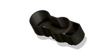
E30 Cup Holder v2
...removable box.<br>the installation location is located next to the handbrake<br>printed abs layer...
3d_export
$10
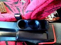
e30 cup holder
...box. the installation location is located next to the handbrake the diameter of the cup is 68 mm. the...
3d_export
$19
Bambino bicycle
...i owned and used one myself in 1965-1966. the handbrake was dangerous; rolling down the hill and using the...
3d_export
$70

lancer evolution 9
...wheel 2 4 sliders for opening each door 3 handbrake down slider 4 sun shades 5 bardachek 6 dashboard...
3d_export
$129

ursus c-355 tractor
...front tank front tires front wheels gauges gear sticks handbrake head lights hydrolic hitch system pedals rear axle rear...
thingiverse
free
Honda Jazz handbrake button
...honda jazz handbrake button
thingiverse
i had a request for a new handbrake button for a honda jazz.
thingiverse
free

Handbrake Simracing by Javi91ac
...handbrake simracing by javi91ac
thingiverse
work in progress
thingiverse
free
Mitsubishi Colt handbrake button by Raptirius
...mitsubishi colt handbrake button by raptirius
thingiverse
mitsubishi colt z34 handbrake button.
thingiverse
free
G27/G25 Handbrake Mount by Roedkill
...g27/g25 handbrake mount by roedkill
thingiverse
simple handbrake mount for the g27/g25 shifter
thingiverse
free
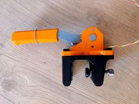
Table Mount For Handbrake
...or an m12 spacer on the bottom side of the print.
this was printed in pla with 3-4 walls while laying on the side with 20% infill
Racing
3ddd
$1
race
...race
3ddd
мотоцикл
race
turbosquid
$15
Racing
...d
royalty free 3d model racing for download as obj and blend on turbosquid: 3d models for games, architecture, videos. (1474846)
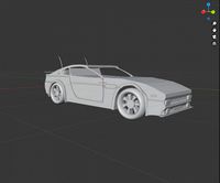
3d_export
$5
racing car
...racing car
3dexport
racing car
3d_export
$5
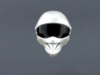
racing helmet
...racing helmet
3dexport
helmet 3d model for motocross or racing cars
3d_export
$5
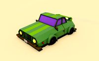
racing car
...racing car
3dexport
low poly classical racing car model
3d_ocean
$29

racing car
...cing car rim seat speed sport sport car tyre
detailed 3d model of racing car. all materials are included. model is ready for use.
3d_ocean
$29

racing car
... rim seat speed spoiler sport sport car tire
detailed 3d model of racing car. all materials are included. model is ready for use.
3d_ocean
$15

Race Car
...race car
3docean
a very detailed and realistic 3d model of a race car, which was created with polygons.
3ddd
$1
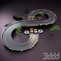
Turbo Racing
... машинка
игрушечная гоночная дорога "turbo racing". почувствуй себя настоящим гонщиком.
3d_export
$100

start race motocross
...start race motocross
3dexport
start race motocross
Pc
archibase_planet
free
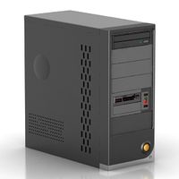
PC
...pc
archibase planet
pc case pc tower pc equipment system unit
pc - 3d model (*.gsm+*.3ds) for interior 3d visualization.
3d_export
free
Pc
...pc
3dexport
pc
archibase_planet
free

PC
...pc
archibase planet
notebook pc computer equipment
pc - 3d model (*.gsm+*.3ds) for interior 3d visualization.
archibase_planet
free
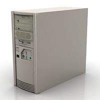
PC
...pc
archibase planet
system unit pc equipment
pc - 3d model (*.gsm+*.3ds) for interior 3d visualization.
archibase_planet
free

PC
...pc
archibase planet
pc equipment cabinet system unit
pc 70 - 3d model (*.gsm+*.3ds) for interior 3d visualization.
3d_export
$5
pc
...pc
3dexport
computer
archibase_planet
free
PC
...pc
archibase planet
cabinet chassis system unit
pc case n241107 - 3d model (*.gsm+*.3ds) for interior 3d visualization.
turbosquid
$3

PC
...id
royalty free 3d model pc for download as ma, obj, and fbx on turbosquid: 3d models for games, architecture, videos. (1159175)
turbosquid
$7

lap top ,pc portable, PC
...ty free 3d model lap top ,pc portable, pc for download as c4d on turbosquid: 3d models for games, architecture, videos. (1352084)
turbosquid
$100
PC
... available on turbo squid, the world's leading provider of digital 3d models for visualization, films, television, and games.
Button
archibase_planet
free
Buttons
...buttons
archibase planet
lift elevator call buttons
elevator call buttons - 3d model for interior 3d visualization.
3ddd
$1
Button
... button , john reeves
набор мебели button от дизайнера john reeves
3d_export
$5
Button
...button
3dexport
smd button<br>verts 2.180<br>faces 3.848
turbosquid
$4

Button
...
turbosquid
royalty free 3d model button for download as fbx on turbosquid: 3d models for games, architecture, videos. (1297941)
turbosquid
$1

Button
...
turbosquid
royalty free 3d model button for download as fbx on turbosquid: 3d models for games, architecture, videos. (1392935)
turbosquid
$9
buttons
...id
royalty free 3d model buttons for download as max and fbx on turbosquid: 3d models for games, architecture, videos. (1404875)
turbosquid
$6

button
...uid
royalty free 3d model button for download as 3dm and max on turbosquid: 3d models for games, architecture, videos. (1669204)
turbosquid
$5
Button
...uid
royalty free 3d model button for download as max and fbx on turbosquid: 3d models for games, architecture, videos. (1710868)
turbosquid
$3

Button
...quid
royalty free 3d model button for download as ma and obj on turbosquid: 3d models for games, architecture, videos. (1510524)
turbosquid
$3
Button
...quid
royalty free 3d model button for download as ma and obj on turbosquid: 3d models for games, architecture, videos. (1509961)
Box
archibase_planet
free
Box
...box
archibase planet
box carton cardboard box
box 2 - 3d model (*.3ds) for interior 3d visualization.
archibase_planet
free
Box
...box
archibase planet
carton cardboard box box
box 1 - 3d model (*.3ds) for interior 3d visualization.
3d_export
$6
box
...box
3dexport
box
3d_export
$5
Box
...box
3dexport
box
3d_export
$5
box
...box
3dexport
box
3d_export
$5
box
...box
3dexport
box
archibase_planet
free
Box
...box
archibase planet
box box for paper notebook pencil
box - 3d model (*.gsm+*.3ds) for interior 3d visualization.
archibase_planet
free
Box
...box
archibase planet
box carton cardboard box
box n170111 - 3d model (*.gsm+*.3ds) for interior 3d visualization.
archibase_planet
free

Box
...box
archibase planet
box carton cardboard box
box n050411 - 3d model (*.gsm+*.3ds) for interior 3d visualization.
archibase_planet
free

Boxes
...boxes
archibase planet
boxes box case bin
boxes n281213 - 3d model (*.gsm+*.3ds+*.max) for interior 3d visualization.