Thingiverse
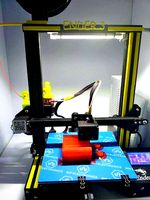
OutFox Zero Clog Multi-Material System (Ender 3 series) by The__Captain
by Thingiverse
Last crawled date: 3 years, 3 months ago
Outfox those persistent clogs in your multimaterial/multicolor printer!
The OutFox multimaterial system is a unique (to my knowledge) approach to eliminating clogs in a FDM bowden system that uses a 2-to-1 (or any X-to-1) adapter.
https://www.youtube.com/watch?v=WRMeYPNUrjs
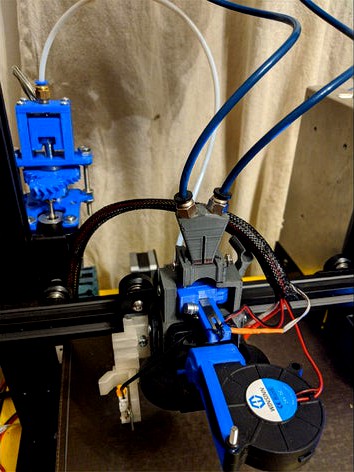
The primary innovation is an inline filament cutter that alleviates the need to retract hot, melted filament from the hotend in order to swap colors/materials. Instead of retracting existing hot filament in order to swap in a new color/material, the filament is cut between the X-to-1 adapter and the hotend. Only then is the old color/material retracted, leaving a segment of old color/material in the hotend. At this point, the new color/material is extruded, pushing out the old color/material through the hotend. This completely avoids the potential for clogging as a result of retracting hot, melted filament from the hotend because hot, melted filament is never actually retracted from the hot end at all.
This modification requires an additional axis (i.e. stepper) to drive the linear actuator which in turn opens and closes the jaws of the inline cutter. How to add another stepper to your machine is beyond the scope of this documentation. Please refer to your manual, local support group, google, etc
The printed parts are many, but none take much more than an hour to print other than the Main Shroud, and some take only minutes.
Aside from the printed parts, you will need:
2 Nema17 steppers. The more torque, the better
1 Extruder. I like BMG clones from Biqu. I would recommend you match your new extruder with your existing extruder
1 M8x1.25x60 (or longer) hex head tap bolt (Note that this is a FINE pitch bolt)
1 M8 fine pitch hex nut
2 M5x50 (or longer) hex bolts
6 M5 nuts
1 Spare 20mmx8mm bed leveling spring (stock is good, yellow springs may be too stiff)
1 Chisel razor blade (37mmx6mm)
1 Bicycle brake cable
2 Bicycle brake cable knarps
2 5mm bowden (push-connect) fittings. (The kind that does NOT permit the tube to pass through)
1 Length of bowden tubing (250mm to 300mm, or enough to reach across your print bed and then some)
2 10mm bowden (push connect) fitting. (The kind that DO permit the tube to pass through)
2 Lengths of bowden tubing (enough to reach from your top rail to your hotend, and then some).
1 Small length of bowden tubing (~80mm)
1 5015 fan
7 M3x10mm screws
2 M3 nuts
2 608 (i.e. skate) bearings
1 twist tie
1 stock extruder hob
2 long stepper cables
Construction
Printed parts are capitalized for easy identification
Almost all holes and cutaways are sized towards the small side, upon the logic that it is easier to spend a few minutes reaming or sanding a tight fit than it is to re-print an entire piece because it was too loose.
Linear actuator assembly
Attach Actuator Cable Adapter to hex head of M8 fine pitch bolt
Insert M8 fine pitch bolt through Actuator Idler. Actuator Cable Adapter should be between the "arms" of the Actuator Idler.
Insert M8 fine pitch nut into Actuator Large Gear
Insert M8 fine pitch bolt through 608 bearing
Screw Actuator Large Gear onto M8 fine pitch bolt. The hex head of the bolt should be on the opposite side of Actuator Large Gear from M8 fine pitch nut.
Insert M8 fine pitch bolt through 608 bearing
Insert M8 fine pitch bolt through Actuator Base Plate
Insert M5 bolts through Actuator Idler
Add two M5 nuts to each M5 bolt
Insert M5 bolts through Actuator Base Plate
Add M5 nut to each M5 bolt. Tighten all M5 nuts.
Push stock extruder hob into Actuator Small Gear
Attach Actuator Small Gear to nema17 stepper
Trim brake cable to size (~100mm longer than first length of bowden tubing in parts list).
Insert brake cable end into Actuator Cable Adapter
(Optional) If brake cable end does not does not fit inside Actuator Cable Adapter, remove existing cable end and replace with cable knarp
Attach (screw in) 5mm bowden connector to Actuator Idler Plate
Attach Actuator Idler Plate to Actuator Idler using M3 screws
Cutter assembly
Attach Cutter Arm to Cutter Base using Cutter Screw
Insert chisel blade through Cutter Arm, secure with twist tie
insert brake cable through Cutter Base, then through bed leveling spring, then through Cutter Arm
Close Cutter Arm so that the chisel blade is barely visible inside the Cutter Base tubing path. There should be a small amount of compression on the bed leveling spring.
Attach cable knarp to end of brake cable.
Y Adapter assembly
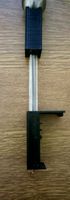
Chamfer both lengths of bowden cable using Chamfer Cutting Guide
Insert one length of tubing into one of the "arms" of the Y adapter until it reaches the internal junction
Insert a razor blade into the slot in the Y adapter, and slice off the side of the inserted tubing.
Remove the length bowden tubing
Repeat previous three steps with second length of cable, using the other "arm" of the Y adapter
Insert both lengths of cable into the Y adapter. They should meet and join perfectly inside the Y adapter (visible from the bottom). Retrim both lengths of tubing if necessary until they can be joined perfectly inside the adapter.
Remove both lengths of tubing
Screw in 10mm bowden connectors to the "arms" of the Y adapter.
Reinsert both lengths of tubing into the Y adapter, confirming once again that they join together perfectly
Attach extruder steppers to Extruder Mounting Adapters
Connect tubing lengths from Y Adapter to extruder steppers
Mount Extruder Mounting Adapters to top rail.
Preliminary Testing
Unload filament
Remove stock shroud and fans
Replace parts fan with 5015 fan [wiring]
Unmount extruder from gantry
Mount cutter stepper and linear actuator assembly to gantry using old extruder mount point.
Insert a scrap piece of bowden tubing into Cutter Base tubing path
Insert a scrap piece of filament into the scrap bowden tubing from previous step
Connect all steppers and turn on printer
Enable cutter stepper and issue a command to retract and feed ~190mm. The linear actuator should pull down the Cable Adapter, causing tension on the brake cable, eventually causing Cutter Arm to cut through the tubing and filament. If your stepper skips or bogs down, you can try adding lubricant to the linear actuator drive bolt, upping the stepper current, disabling StealthChop, getting a better stepper, etc, etc. You can also adjust the cable knarp that sits against the cutter arm if the filament is not getting cut (cable length is too long), or the cutting blade blocks the filament path (cable length is too short).
Completion
When the previous step can be repeated successfully to your satisfaction, attach Main Shroud to printer carriage using two existing stock shroud screws
Attach stock fan to Main Shroud using stock fan screws
Attach Bullseye Fang to Main Shroud using M3x12mm screws
Fully insert short bowden tubing length into hotend bowden coupler
Test tubing length by inserting Y Adapter into socket on top of Main Shroud. Trim tubing until Y Adapter can be fully inserted into Main Shroud, but trim it NO SHORTER.
Remove short tubing length from hotend.
Mount Cutter Base to Main Shroud using M3x10mm screw
Insert short bowden tube into Y Adapter Plug. Leave ~10mm of tubing extending through Y Adapter Plug
Fully insert short bowden tubing length through Main Shroud from above, through Cutter Base tubing path and into hotend bowden connector.
Insert Y Adapter into socket on top of Main Shroud, and onto short bowden tubing length
Secure Y Adapter to Main Shroud using M3x10mm screws
Raise Y Adapter Plug until it rests fully inside Y Adapter.
Attach 5015 fan to 5015 Adapter 90deg
Attach 5015 Adapter 90deg to Bullseye Fang using stock parts fan screws
The OutFox multimaterial system is a unique (to my knowledge) approach to eliminating clogs in a FDM bowden system that uses a 2-to-1 (or any X-to-1) adapter.
https://www.youtube.com/watch?v=WRMeYPNUrjs
The primary innovation is an inline filament cutter that alleviates the need to retract hot, melted filament from the hotend in order to swap colors/materials. Instead of retracting existing hot filament in order to swap in a new color/material, the filament is cut between the X-to-1 adapter and the hotend. Only then is the old color/material retracted, leaving a segment of old color/material in the hotend. At this point, the new color/material is extruded, pushing out the old color/material through the hotend. This completely avoids the potential for clogging as a result of retracting hot, melted filament from the hotend because hot, melted filament is never actually retracted from the hot end at all.
This modification requires an additional axis (i.e. stepper) to drive the linear actuator which in turn opens and closes the jaws of the inline cutter. How to add another stepper to your machine is beyond the scope of this documentation. Please refer to your manual, local support group, google, etc
The printed parts are many, but none take much more than an hour to print other than the Main Shroud, and some take only minutes.
Aside from the printed parts, you will need:
2 Nema17 steppers. The more torque, the better
1 Extruder. I like BMG clones from Biqu. I would recommend you match your new extruder with your existing extruder
1 M8x1.25x60 (or longer) hex head tap bolt (Note that this is a FINE pitch bolt)
1 M8 fine pitch hex nut
2 M5x50 (or longer) hex bolts
6 M5 nuts
1 Spare 20mmx8mm bed leveling spring (stock is good, yellow springs may be too stiff)
1 Chisel razor blade (37mmx6mm)
1 Bicycle brake cable
2 Bicycle brake cable knarps
2 5mm bowden (push-connect) fittings. (The kind that does NOT permit the tube to pass through)
1 Length of bowden tubing (250mm to 300mm, or enough to reach across your print bed and then some)
2 10mm bowden (push connect) fitting. (The kind that DO permit the tube to pass through)
2 Lengths of bowden tubing (enough to reach from your top rail to your hotend, and then some).
1 Small length of bowden tubing (~80mm)
1 5015 fan
7 M3x10mm screws
2 M3 nuts
2 608 (i.e. skate) bearings
1 twist tie
1 stock extruder hob
2 long stepper cables
Construction
Printed parts are capitalized for easy identification
Almost all holes and cutaways are sized towards the small side, upon the logic that it is easier to spend a few minutes reaming or sanding a tight fit than it is to re-print an entire piece because it was too loose.
Linear actuator assembly
Attach Actuator Cable Adapter to hex head of M8 fine pitch bolt
Insert M8 fine pitch bolt through Actuator Idler. Actuator Cable Adapter should be between the "arms" of the Actuator Idler.
Insert M8 fine pitch nut into Actuator Large Gear
Insert M8 fine pitch bolt through 608 bearing
Screw Actuator Large Gear onto M8 fine pitch bolt. The hex head of the bolt should be on the opposite side of Actuator Large Gear from M8 fine pitch nut.
Insert M8 fine pitch bolt through 608 bearing
Insert M8 fine pitch bolt through Actuator Base Plate
Insert M5 bolts through Actuator Idler
Add two M5 nuts to each M5 bolt
Insert M5 bolts through Actuator Base Plate
Add M5 nut to each M5 bolt. Tighten all M5 nuts.
Push stock extruder hob into Actuator Small Gear
Attach Actuator Small Gear to nema17 stepper
Trim brake cable to size (~100mm longer than first length of bowden tubing in parts list).
Insert brake cable end into Actuator Cable Adapter
(Optional) If brake cable end does not does not fit inside Actuator Cable Adapter, remove existing cable end and replace with cable knarp
Attach (screw in) 5mm bowden connector to Actuator Idler Plate
Attach Actuator Idler Plate to Actuator Idler using M3 screws
Cutter assembly
Attach Cutter Arm to Cutter Base using Cutter Screw
Insert chisel blade through Cutter Arm, secure with twist tie
insert brake cable through Cutter Base, then through bed leveling spring, then through Cutter Arm
Close Cutter Arm so that the chisel blade is barely visible inside the Cutter Base tubing path. There should be a small amount of compression on the bed leveling spring.
Attach cable knarp to end of brake cable.
Y Adapter assembly
Chamfer both lengths of bowden cable using Chamfer Cutting Guide
Insert one length of tubing into one of the "arms" of the Y adapter until it reaches the internal junction
Insert a razor blade into the slot in the Y adapter, and slice off the side of the inserted tubing.
Remove the length bowden tubing
Repeat previous three steps with second length of cable, using the other "arm" of the Y adapter
Insert both lengths of cable into the Y adapter. They should meet and join perfectly inside the Y adapter (visible from the bottom). Retrim both lengths of tubing if necessary until they can be joined perfectly inside the adapter.
Remove both lengths of tubing
Screw in 10mm bowden connectors to the "arms" of the Y adapter.
Reinsert both lengths of tubing into the Y adapter, confirming once again that they join together perfectly
Attach extruder steppers to Extruder Mounting Adapters
Connect tubing lengths from Y Adapter to extruder steppers
Mount Extruder Mounting Adapters to top rail.
Preliminary Testing
Unload filament
Remove stock shroud and fans
Replace parts fan with 5015 fan [wiring]
Unmount extruder from gantry
Mount cutter stepper and linear actuator assembly to gantry using old extruder mount point.
Insert a scrap piece of bowden tubing into Cutter Base tubing path
Insert a scrap piece of filament into the scrap bowden tubing from previous step
Connect all steppers and turn on printer
Enable cutter stepper and issue a command to retract and feed ~190mm. The linear actuator should pull down the Cable Adapter, causing tension on the brake cable, eventually causing Cutter Arm to cut through the tubing and filament. If your stepper skips or bogs down, you can try adding lubricant to the linear actuator drive bolt, upping the stepper current, disabling StealthChop, getting a better stepper, etc, etc. You can also adjust the cable knarp that sits against the cutter arm if the filament is not getting cut (cable length is too long), or the cutting blade blocks the filament path (cable length is too short).
Completion
When the previous step can be repeated successfully to your satisfaction, attach Main Shroud to printer carriage using two existing stock shroud screws
Attach stock fan to Main Shroud using stock fan screws
Attach Bullseye Fang to Main Shroud using M3x12mm screws
Fully insert short bowden tubing length into hotend bowden coupler
Test tubing length by inserting Y Adapter into socket on top of Main Shroud. Trim tubing until Y Adapter can be fully inserted into Main Shroud, but trim it NO SHORTER.
Remove short tubing length from hotend.
Mount Cutter Base to Main Shroud using M3x10mm screw
Insert short bowden tube into Y Adapter Plug. Leave ~10mm of tubing extending through Y Adapter Plug
Fully insert short bowden tubing length through Main Shroud from above, through Cutter Base tubing path and into hotend bowden connector.
Insert Y Adapter into socket on top of Main Shroud, and onto short bowden tubing length
Secure Y Adapter to Main Shroud using M3x10mm screws
Raise Y Adapter Plug until it rests fully inside Y Adapter.
Attach 5015 fan to 5015 Adapter 90deg
Attach 5015 Adapter 90deg to Bullseye Fang using stock parts fan screws
Similar models
thingiverse
free

Ender 3 Pro DirectDrive Extruder Mount
...is modification at your own risk.
update to version 2.1:
added support on rear side to increase rigidity during filament retracts
thingiverse
free

Triod3D Bowden Extruder V1 by MarinusK
...4 bsp.
the arm requires a m4 nut and 10mm screw as well as a filament guide with a height of 3mm and diameter of 13mm up to 15mm.
thingiverse
free

direct drive bowden extruder for 1.75 mm filament by dborlaug
...ruder examples. thank you open source reprap community.
successfully printed and assembled, but yet untested as of 2014-05-04.
thingiverse
free

Printrbot LC Bowden Cable Mod by piit79
...den cable feed:
-- extruder to bowden including x-idler mounting bracket and insert
-- bowden to hotend
this is for 3mm filament.
thingiverse
free

CR-10 S5 Bowden & Hotend Cable Arm by BobMcG
...olts,
2x m5 drop in nuts.
print as orientated, does not require supports. recommend abs, 20% honeycomb infill, but not essential.
thingiverse
free

Wischis Extruder Cable Support by wischi
...rt really quick.
it lets you attach the cables for hotend, hotend sensor and stepper to the stepper with a screw and cabletie.
thingiverse
free

D-Bot Fully-Supported Extruder by dotorg
...d one on the right, so there's versions for either side uploaded. you only need to print the two parts for the side you want.
thingiverse
free

D-Bot Bowden/Cable Arm by mktacop
...e for my d-bot, so i created one. it attaches with 2 m5x10 bolts, 2 m5 washers, and 2 m5 drop-in t-nuts. i printed it in petg.
thingiverse
free

Wades extruder to bowden adapter
...wades to bowden adapter. fits into the bottom of a wades extruder to convert it into a bowden tube setup instead of a e3d hotend.
thingiverse
free

SK-GO/Pallet 2 bowden adapter by amooz
..., you can squish the rubber gasket into the hole for a perfect fit. i printed at 100% infill since this will be a stressed part.
Clog
turbosquid
$55

Clogs
...yalty free 3d model clogs for download as blend, fbx, and obj on turbosquid: 3d models for games, architecture, videos. (1612458)
turbosquid
$39

Clog shoes (02)
... available on turbo squid, the world's leading provider of digital 3d models for visualization, films, television, and games.
3d_export
$15

Kid Classic Clog 3D Model
...kid classic clog 3d model
3dexport
kid classic clog shoe shoes
kid classic clog 3d model maxtecb 59504 3dexport
cg_studio
$49

Clog shoes (01)3d model
...og shoes (01)3d model
cgstudio
.max - clog shoes (01) 3d model, royalty free license available, instant download after purchase.
3d_ocean
$4

Turkish Bath Hamam Takunya ( Basic Wooden Clog )
...takunya ” . these historical shoes used in turkish bath ( hamam ). there are small pieces of nacre . ” sedef kakma” was art of...
3d_export
$23

wooden clogs
...for high-quality render results. no extra plugins are required for this model. lights and cameras are not included in the scenes.
3d_export
$35

rubber flash clogs
... get the best results in blender. no extra plugins are required for this model. lights and cameras are not included in the scene.
cg_studio
$25

medical clogs3d model
...ar hospital nurse dress
.3ds .max .obj - medical clogs 3d model, royalty free license available, instant download after purchase.
3d_export
$5

Plunger 3D Model
...model 3dexport toilets bathroom tool tools plunger poop clog cloged toilet sink drain pipe plumber suction sanitary rubber household...
3d_export
$5

Farmer Cartoon RIGGED 3D Model
...model 3dexport guy farmer cartoon toon fantasy rigged gardener clog pumpkin vegetable fork wheelbarrows hat anime dessin fermier chapeau...
Captain
3ddd
free

Captain
... captain , кресло
кресло captain от мебельной фабрики sinetica.
материалы corona.
3d_export
$5

captain-america-
...captain-america-
3dexport
captain-america-
3d_export
$5

captain marvel
...captain marvel
3dexport
captain marvel
3d_export
$5

captain america
...captain america
3dexport
captain america for 3d print
turbosquid
$99

Captain
... available on turbo squid, the world's leading provider of digital 3d models for visualization, films, television, and games.
design_connected
$13

Captain Flint
...captain flint
designconnected
captain flint computer generated 3d model. designed by anastassiades, michael.
3d_export
$5

Shield of captain america
...shield of captain america
3dexport
keychain of shield of captain america
3d_export
$7

captain america shield
...captain america shield
3dexport
captain america shield made by me
turbosquid
$25

Captain Chair
...quid
royalty free 3d model captain chair for download as obj on turbosquid: 3d models for games, architecture, videos. (1500418)
3ddd
$1

Captain Cork S
... captain , пробка
диаметр - 14,5см
высота - 19см
Zero
3ddd
$1
ZERO, BEAM
...zero, beam
3ddd
zero
поворотная люстра zero , beam
design_connected
$9
Zero-in
...zero-in
designconnected
established & sons zero-in tables computer generated 3d model. designed by jay osgerby .
3ddd
free
Sub-Zero
...sub-zero
3ddd
sub-zero , голова
sub-zero corona render!
3ddd
$1
Metalspot / Zero
...metalspot / zero
3ddd
metalspot
metalspot zero
3ddd
$1
Catalano Zero
...catalano zero
3ddd
catalano , унитаз
catalano zero
3ddd
$1

SUB ZERO
... sub zero
the first and only 3d model of sub zero refrigerator.
the model is very accurate.
turbosquid
free
Zero
... available on turbo squid, the world's leading provider of digital 3d models for visualization, films, television, and games.
turbosquid
free
Zero
... available on turbo squid, the world's leading provider of digital 3d models for visualization, films, television, and games.
turbosquid
free
Zero
... available on turbo squid, the world's leading provider of digital 3d models for visualization, films, television, and games.
3ddd
$1

ZERO / Hide
...zero / hide
3ddd
zero
polys: 25486
wire-spline
Ender
3ddd
$1
Enders / Elegance
...enders / elegance
3ddd
обогреватель
уличный газовый обогреватель enders elegance
высота: 2200 мм
3d_export
free
ender 3 frame cavity covers
... of the creality ender 3 - makes it look a bit more attractive it just slides into the open channels of the aluminium framework
turbosquid
$1
pen support for ender 3
...y free 3d model pen support for ender 3 for download as blend on turbosquid: 3d models for games, architecture, videos. (1611282)
3d_ocean
$9
Ender Dragon Minecraft
...ojang obj poly videogames
ender dragon minecraft created with cinema 4d r15 formats included: max 2013 – fbx 2012 – c4d r15 – obj
3d_export
free
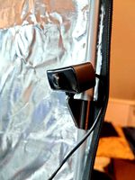
Creality ender enclosure webcam mount
...e creality enclosure. sure is better than a tripod. change it up if it helps. i printed pla with 50% infill on my dd ender 3 pro.
3d_export
free
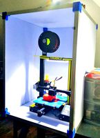
ender 3 enclosure corners
...er corners and 4 upper corners, using 25mmx25mm angled aluminium pieces that gets covered on inside of the frame with plexiglass
3d_export
free
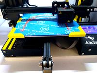
ender 3 3d print bed clips
...ed + normal aluminium bed frame of the creality ender 3 = 6mm (b) these clips are designed for glass plate + aluminium bed = 4mm
3d_export
$5
GRUMPY CAT
...grumpy cat 3dexport grumpy cat to print in ender ...
3d_export
$5

Logs fire
...with one multi material for corona and vray r ender. albedo, normal, uvmap, roughness format jpg 4096x4096 models:...
3d_export
$42
excavator
...is the original size. 0.12 mm printing surface creality ender5 ...
Multi
3d_export
$5
multi handle
...multi handle
3dexport
multi handle
3d_export
free
Multi socket
...multi socket
3dexport
multi socket
design_connected
$22

Multy Loveseat
...multy loveseat
designconnected
ligne roset multy loveseat 2-seater computer generated 3d model. designed by claude brisson.
turbosquid
$10
multi pan
...
royalty free 3d model multi pan for download as max and ige on turbosquid: 3d models for games, architecture, videos. (1161690)
turbosquid
$9

Multi Plug
...
royalty free 3d model multi plug for download as max and fbx on turbosquid: 3d models for games, architecture, videos. (1355953)
turbosquid
$39
Multi Gym
...y free 3d model multi gym for download as obj, fbx, and blend on turbosquid: 3d models for games, architecture, videos. (1275571)
3ddd
free
Ligne Roset Multy
... sofa , мебель
двухместный диван multy от французского производителя ligne roset
3d_export
$5

multi-colored pencils
...multi-colored pencils
3dexport
multi-colored pencils on a mirror surface
3d_export
$5
multi function box
...multi function box
3dexport
it is multi function box in iges format
3ddd
free
ligne roset / MULTY
...ligne roset / multy
3ddd
ligne roset , multy
минималистический диван
Series
design_connected
$13

T-Series
...t-series
designconnected
bolia t-series computer generated 3d model. designed by burgess, james.
3ddd
$1
SYSTEMPOOL Serie Curve
..., serie curve , раковина
systempool serie curve
3ddd
free

Table Series 1
... series 1 , обеденный
table series 1 for dining room.
3ddd
free
KOLARZ Serie Explosion
... serie explosion , австрия
kolarz serie explosion 0109.118.5.kot. врай. текстуры.
3d_export
$8

jwm series elevator
...jwm series elevator
3dexport
jwm series elevator
3ddd
$1

Cappellini Serie 331
...cappellini serie 331
3ddd
cappellini
cappellini serie 331
3ddd
free

R3310 POS Series
...r3310 pos series
3ddd
терминал
r3310 pos series
turbosquid
$19

A series of curtains
...oyalty free 3d model a series of curtains for download as max on turbosquid: 3d models for games, architecture, videos. (1440593)
turbosquid
$5

kitchen a series
...model kitchen a series for download as 3ds, max, obj, and fbx on turbosquid: 3d models for games, architecture, videos. (1423903)
3ddd
$1

DURAVIT 1930 Series
...duravit 1930 series
3ddd
duravit , угловой
угловая раковина duravit 1930 series
System
archibase_planet
free
System
...m
archibase planet
fire alarm system fire alarm box
security light system - 3d model (*.gsm+*.3ds) for interior 3d visualization.
archibase_planet
free
Spider system
...stem spider glass system
spider system to fix glass stefano galli n050912 - 3d model (*.gsm+*.3ds) for interior 3d visualization.
3ddd
$1
Euforia System
...euforia system
3ddd
euforia
euforia system
3d_export
$50
Roof system Truss system 3D Model
...oof system truss system 3d model
3dexport
roof system truss truss stage
roof system truss system 3d model aleksbel 38970 3dexport
3ddd
$1
DVD System
...dvd system
3ddd
dvd , schneider
dvd system
design_connected
free
Seating system
...seating system
designconnected
free 3d model of seating system
3d_export
$5

solar system
...solar system
3dexport
solar system in c4d, with 8k nasa textures
3ddd
$1
Quanta System
...quanta system
3ddd
медицина
quanta system.
лазерное оборудование для медицинских центров
3d_export
$15
solar system
...nd the other the sun, the earth and the moon, the latter has an animation with camera movement included, the files are in spanish
3d_export
$14

missile system
...missile system
3dexport
3
turbosquid
$10
Mountain Bike 3 -3 of 3
...model mountain bike 3 (#3 of 3) for download as fbx and blend on turbosquid: 3d models for games, architecture, videos. (1438752)
turbosquid
$3

Genesis 3 Clothing 3
... available on turbo squid, the world's leading provider of digital 3d models for visualization, films, television, and games.
3d_export
$5
hinge 3
...hinge 3
3dexport
hinge 3
3ddd
$1
Розетка 3
...розетка 3
3ddd
розетка
розетка 3
turbosquid
$50

is-3
... available on turbo squid, the world's leading provider of digital 3d models for visualization, films, television, and games.
turbosquid
$10
Mountain Bike 3 -2 of 3
...model mountain bike 3 (#2 of 3) for download as fbx and blend on turbosquid: 3d models for games, architecture, videos. (1438750)
turbosquid
$10
Mountain Bike 1 -3 of 3
...model mountain bike 1 (#3 of 3) for download as fbx and blend on turbosquid: 3d models for games, architecture, videos. (1438743)
3d_export
$5

3 CATS
...3 cats
3dexport
3 cats pen holder
3ddd
free
3 Буфета
...3 буфета
3ddd
буфет , кантри
3 буфета
turbosquid
$12

Calligraphic Digit 3 Number 3
...hic digit 3 number 3 for download as max, obj, fbx, and blend on turbosquid: 3d models for games, architecture, videos. (1389329)
Material
3d_export
$245
top of the material
...top of the material
3dexport
top of the material,commercial ceiling ceiling material, metal material
3d_ocean
$5

Concrete material
...concrete material
3docean
concrete cover material realistic textures
realistic concrete material
3d_ocean
$3

Grass Material
...grass material
3docean
grass material
include normal map
3d_ocean
$3

Terrain material
...terrain material
3docean
terrain material include normal map
3d_ocean
$3

Wood Material
...wood material
3docean
wood material include normal map
vizpark
$10

Material Manager
...ager
vizpark
the vp material manager is a new innovative tool to manage materials within 3ds max® in ways never possible before.
vizpark
free

Material Manager
...ager
vizpark
the vp material manager is a new innovative tool to manage materials within 3ds max® in ways never possible before.
3d_ocean
$7

R16 Material Kit(50+ Materials!)
...ls -fabrics -automotive materials -architectural materials -a complimentary studio -abstract materials -rocks all for the pric...
3d_ocean
$5

Frozen Materials
...erials the project includes the frozen materials and frosted effect. for the material included diffuse and map normal. thank you!
design_connected
$16

Material Pendant
...material pendant
designconnected
new works material pendant computer generated 3d model. designed by noergaard & kechayas.