Thingiverse
Optical Filament Runout Sensor by clarionite
by Thingiverse
Last crawled date: 2 years, 11 months ago
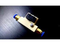
I had a mechanical runout sensor on my Ender 5, but had a couple of breaks in the filament between the sensor and the extruder. So it wasn't doing me any good. It also couldn't detect a clog, and since I'm printing more with TPU (Ninjaflex) I wanted something that would allow me to clear the clog and keep me from wasting several hours and some expensive filament.
A friend sent me a copy of the sensor he was using, but I ordered the wrong bearings for the one he had. So I ended up making this file from scratch. I need the practice in Design spark anyways.
I've included the Designspark file, so you can tweak it however you'd like.
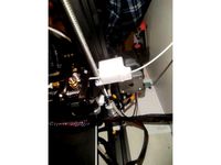
The mount is designed to allow you to mount it vertically or horizontally.
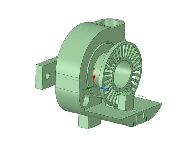
I printed the decoder in two parts. The wheel in ABS, and the base in TPU. You can print this in one piece in whatever filament you have lying around PLA should work. And put a rubber band around the base, or get a small balloon and slice across it to make a band to put over the base.
I designed the path just wide enough to squeeze a piece of bowden tube in, and then trimmed the inside with a razer blade, so the filament will have a narrow path and just enough was cut away for the encoder to press against it.
The cable that comes with the sensor is pretty short. But I was replacing a mechanical sensor on my ender, so I just used the one I already had. I did have to switch the ground and signal wires at one end.
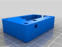
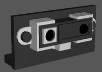
The magnets are pretty strong, and you won't have any issues with the cover coming off.
Make sure when you press the magnets you pair two together, put them in the cover, and then with them mated press them into the case. If you get them in backwards the magnets will repel each other, and there's no way to get the magnets back out once they're pressed in.
Magnets to make cover quick disconnect (4 needed)
https://www.amazon.com/gp/product/B07873ZCY4/ref=ppx_yo_dt_b_asin_title_o00_s00?ie=UTF8&psc=1
Bearing (1 needed)
https://www.amazon.com/gp/product/B07S1B3MS6/ref=ppx_yo_dt_b_asin_title_o00_s00?ie=UTF8&psc=1
Sensor (1 needed)
https://www.amazon.com/gp/product/B0719K9Z9R/ref=ppx_yo_dt_b_asin_title_o07_s00?ie=UTF8&psc=1
Pneumatic fittings (2 needed)
https://www.amazon.com/BIQU-Straight-Pneumatic-Connector-Extruder/dp/B01IB81IHG/ref=sr_1_6?dchild=1&keywords=pneumatic+fitting+for+bowden&qid=1620499139&sr=8-6
m3 x 6 screws 2 needed to secure sensor.
m3 nut 1 needed for mount.
2 m3 T nuts needed for mounting in v slots.
m3 x 12 screws 2 needed for mount.
Whatever length you need for your setup, I used 12mm.
You'll have to enable the optical sensor in Marlin (or whatever FW you're using)
You might have to play with the distance to get it sensitive enough to trigger when you have a clog, but not too sensitive that it has false hits.
https://marlinfw.org/docs/hardware/endstops.html
https://www.instructables.com/Configuring-Endstops-on-Ramps-14-with-Marlin-firmw/
EDIT: If you're using Marlin, and adding a motion sensor for the first time...
FILAMENT_RUNOUT_DISTANCE_MM gets set in your Configuration.h file
and you'll want to make sure FILAMENT_MOTION_SENSOR is defined.
But the EProm probably will have 0 stored for the distance. So you'll need to load the default values, or change the distance via your LCD.
Mine is triggering at just over 1mm, Seems to work well at 5mm, but I set it to 7mm in case I have any noise happening.
Good thing is that I have my load/unload distances and priming distance and speed down perfectly after all this testing.
A friend sent me a copy of the sensor he was using, but I ordered the wrong bearings for the one he had. So I ended up making this file from scratch. I need the practice in Design spark anyways.
I've included the Designspark file, so you can tweak it however you'd like.
The mount is designed to allow you to mount it vertically or horizontally.
I printed the decoder in two parts. The wheel in ABS, and the base in TPU. You can print this in one piece in whatever filament you have lying around PLA should work. And put a rubber band around the base, or get a small balloon and slice across it to make a band to put over the base.
I designed the path just wide enough to squeeze a piece of bowden tube in, and then trimmed the inside with a razer blade, so the filament will have a narrow path and just enough was cut away for the encoder to press against it.
The cable that comes with the sensor is pretty short. But I was replacing a mechanical sensor on my ender, so I just used the one I already had. I did have to switch the ground and signal wires at one end.
The magnets are pretty strong, and you won't have any issues with the cover coming off.
Make sure when you press the magnets you pair two together, put them in the cover, and then with them mated press them into the case. If you get them in backwards the magnets will repel each other, and there's no way to get the magnets back out once they're pressed in.
Magnets to make cover quick disconnect (4 needed)
https://www.amazon.com/gp/product/B07873ZCY4/ref=ppx_yo_dt_b_asin_title_o00_s00?ie=UTF8&psc=1
Bearing (1 needed)
https://www.amazon.com/gp/product/B07S1B3MS6/ref=ppx_yo_dt_b_asin_title_o00_s00?ie=UTF8&psc=1
Sensor (1 needed)
https://www.amazon.com/gp/product/B0719K9Z9R/ref=ppx_yo_dt_b_asin_title_o07_s00?ie=UTF8&psc=1
Pneumatic fittings (2 needed)
https://www.amazon.com/BIQU-Straight-Pneumatic-Connector-Extruder/dp/B01IB81IHG/ref=sr_1_6?dchild=1&keywords=pneumatic+fitting+for+bowden&qid=1620499139&sr=8-6
m3 x 6 screws 2 needed to secure sensor.
m3 nut 1 needed for mount.
2 m3 T nuts needed for mounting in v slots.
m3 x 12 screws 2 needed for mount.
Whatever length you need for your setup, I used 12mm.
You'll have to enable the optical sensor in Marlin (or whatever FW you're using)
You might have to play with the distance to get it sensitive enough to trigger when you have a clog, but not too sensitive that it has false hits.
https://marlinfw.org/docs/hardware/endstops.html
https://www.instructables.com/Configuring-Endstops-on-Ramps-14-with-Marlin-firmw/
EDIT: If you're using Marlin, and adding a motion sensor for the first time...
FILAMENT_RUNOUT_DISTANCE_MM gets set in your Configuration.h file
and you'll want to make sure FILAMENT_MOTION_SENSOR is defined.
But the EProm probably will have 0 stored for the distance. So you'll need to load the default values, or change the distance via your LCD.
Mine is triggering at just over 1mm, Seems to work well at 5mm, but I set it to 7mm in case I have any noise happening.
Good thing is that I have my load/unload distances and priming distance and speed down perfectly after all this testing.
Similar models
thingiverse
free

Filament Runout Sensor Side Mount for Creality,Tivo
...amazon.com/gp/product/b07n2gqhqt/ref=ppx_yo_dt_b_asin_title_o02_s00?ie=utf8&psc=1
you will need a few m3 screws and m3 t nuts
thingiverse
free

Desk Fan by NebNorse
...lpages04?ie=utf8&psc=1
motor control: https://www.amazon.com/gp/product/b01cnl6imc/ref=od_aui_detailpages04?ie=utf8&psc=1
thingiverse
free

Watchmakers Screwdriver Stand
...utf8&psc=1
the filament is: https://www.amazon.com/gp/product/b071cnlmdv/ref=ppx_yo_dt_b_asin_title_o06_s01?ie=utf8&psc=1
thingiverse
free

12 Function Deep Dish Button Box by coyoteyz13
..._title_o03_s00?ie=utf8&psc=1
https://www.amazon.com/gp/product/b07vhcb1q4/ref=ppx_yo_dt_b_search_asin_title?ie=utf8&psc=1
thingiverse
free

Guitar Pickup Winder
...=utf8&psc=1
speed adjustmenthttps://www.amazon.com/gp/product/b07vpnhs5j/ref=ppx_yo_dt_b_asin_title_o02_s01?ie=utf8&psc=1
thingiverse
free

Tpcast Vive Sensor Mount by kaptainkarl2
...you will need the following screws:
https://www.amazon.com/gp/product/b008rnlrek/ref=oh_aui_detailpage_o02_s00?ie=utf8&psc=1
thingiverse
free

Voxelab Aquila filament runout sensor holder (dual gear) by kuldeeppatel123
...uder : https://www.amazon.com/gp/product/b07sy745cf/ref=ppx_yo_dt_b_asin_title_o02_s01?ie=utf8&psc=1
no extra hardware needed
thingiverse
free

Sonoff Enclosure by JeffLZ
...title_o00_s00?ie=utf8&psc=1
https://www.amazon.com/gp/product/b00qvb6qpu/ref=ox_sc_saved_title_1?smid=atvpdkikx0der&psc=1
thingiverse
free

Turntable
...amp;psc=1
m3 screws m3x6 or m3x8https://www.amazon.com/gp/product/b07twz7x38/ref=ppx_yo_dt_b_asin_title_o03_s00?ie=utf8&psc=1
thingiverse
free

Freefly AB Gold Mount Adapter by cazmovi
...m3 bolts and m3 screws, about 17mm long or a 18mm long one with washers.
you do not need to use a fuse however it is recommended.
Clarionite
thingiverse
free

V Frame extruder mount by clarionite
...ruder to accept the filament from the right hand side of the frame. so i made this and it works perfectly. thought i'd share.
thingiverse
free

Da Vinci mounting bracket by clarionite
...er once i've got everything lined out detailing what i did with my printer. but for now it's just the file for the mount.
thingiverse
free

Da Vinci 1.0a Camera Mount by clarionite
...eused it for this, so no hardware is needed.
i printed this in abs, but i'm sure it would work just as well with pla or petg.
thingiverse
free

Wire Shelf Snap Sleeve for 1" support bars by clarionite
...ment and tools. so i measured the existing ones, mocked up a draft in dsm. and in a couple of hours i had a fully assembled rack.
Runout
3d_export
$6
clamping mechanism of heavy workpiece
...load<br>the inertia force at the maximum acceleration of horizontal runout is less than the retraction side thrust of cylinder.<br>selection...
thingiverse
free
Filament runout sensor by TA1AUB
...filament runout sensor by ta1aub
thingiverse
filament runout sensor
thingiverse
free
Runout filament sensor by davidix68
...runout filament sensor by davidix68
thingiverse
ender 3 runout sensor microswitch case
thingiverse
free
runout sensor -bowden by chroja
...runout sensor -bowden by chroja
thingiverse
runout sensor -bowden
v5 optimalize design
thingiverse
free

Filament runout sensor by jos
.../webshop/cartesio-shop/electronics/filament-runout-sensor
for assembly :http://mauk.cc/mediawiki/index.php/filament_runout_sensor
thingiverse
free

Filament runout by pochetto
...y pochetto
thingiverse
easy filament runout.
1 endstop
1 led
nel firmware attivare la funzione di fine filo e assegnare un pin.
thingiverse
free

Filament runout sensor support by 100s99s
...filament runout sensor support by 100s99s
thingiverse
support for filament runout sensor of direct drive.
thingiverse
free

Swivel mount runout sensor by notnyt
...swivel mount runout sensor by notnyt
thingiverse
608 bearing mounted filament runout sensor
thingiverse
free

Filament runout sensor fastener by Cherepok
...filament runout sensor fastener by cherepok
thingiverse
movable adjustable mount for bigtreetech filament runout sensor.
thingiverse
free

Runout gauge for pulley by tom4cad
...runout gauge for pulley by tom4cad
thingiverse
20t pulley with 5 mm bore. measured runout 0,07 mm
edit
tool with 8mm hole added
Optical
design_connected
$9

Optic
...optic
designconnected
alessi optic computer generated 3d model. designed by colombo, joe.
3ddd
$1

обои OPTIC
...обои optic
3ddd
в архиве текстуры и фото обоев из коллекции optic.
archive3d
free
Optics 3D Model
...optics 3d model
archive3d
optics
optics - 3d model (*.gsm+*.3ds) for interior 3d visualization.
turbosquid
$49

optical eyewear
...id
royalty free 3d model optical eyewear for download as max on turbosquid: 3d models for games, architecture, videos. (1592243)
3d_ocean
$5

optical mouses
...al mouses
3docean
3d models computer electronics mouse
optical mouses 3d models. realistic mouse model. custom and unique design.
turbosquid
$10

Optic cross
...yalty free 3d model optic cross for download as sldas and ige on turbosquid: 3d models for games, architecture, videos. (1683403)
turbosquid
$7

OPTIC Mirror
... free 3d model optic mirror for download as max, obj, and fbx on turbosquid: 3d models for games, architecture, videos. (1223927)
turbosquid
free

Fiber optics
...d model fiber optics for download as 3ds, obj, fbx, and blend on turbosquid: 3d models for games, architecture, videos. (1211912)
turbosquid
$8

Mouse optical
...3d model mouse optical for download as 3ds, obj, c4d, and fbx on turbosquid: 3d models for games, architecture, videos. (1504476)
turbosquid
free

Optical puzzle
... optical puzzle for download as max, ige, fbx, stl, and sldas on turbosquid: 3d models for games, architecture, videos. (1405925)
Sensor
3d_export
free

parking sensor
...parking sensor
3dexport
car parking sensor
turbosquid
$1
Sensor
... available on turbo squid, the world's leading provider of digital 3d models for visualization, films, television, and games.
3d_export
$5
Smoke sensor
...port
smoke sensor, can be an impressive element for your projects. easy to use, realistic image, low polygon, quality materials.
3d_export
$5
Air Quality Sensor v1
...air quality sensor v1
3dexport
air quality sensor v1
3d_export
$15
float sensor
...e up render. - all parts and materials are logically named. other formats ================= - collada (.dae) - autodesk fbx - obj
turbosquid
$26
Wind sensor C
...free 3d model wind sensor c for download as 3ds, obj, and fbx on turbosquid: 3d models for games, architecture, videos. (1328943)
turbosquid
$26
Wind sensor B
...free 3d model wind sensor b for download as 3ds, obj, and fbx on turbosquid: 3d models for games, architecture, videos. (1328168)
3d_export
$5
ultrasound sensor
...ivers convert ultrasound into electrical signals, and transceivers can both transmit and receive ultrasound. export in: -obj -fbx
3ddd
free

Вытяжка Shindo pallada sensor
... вытяжка
вытяжка shindo pallada sensor. в двух размерах - 600 и 900. текстуры в комплекте.
turbosquid
$52
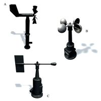
Wind sensor A B C
...
royalty free 3d model wind sensor a b c for download as fbx on turbosquid: 3d models for games, architecture, videos. (1408406)
Filament
3ddd
$1
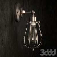
Filament Cage
...filament cage
3ddd
лофт , filament cage
модель бра, делалась по фото!
turbosquid
$3

FILAMENT COUNTER
...d
royalty free 3d model filament counter for download as stl on turbosquid: 3d models for games, architecture, videos. (1563049)
3d_export
$5

Filament lamp 3D Model
...filament lamp 3d model
3dexport
filament lamp 3d model kevin 54161 3dexport
3d_export
$5

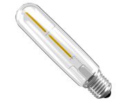
Filament led light bulb
...filament led light bulb
3dexport
realistic 3d model of filament light bulb with v-ray materials.
3d_export
$5

Filament led light bulb
...filament led light bulb
3dexport
realistic 3d model of filament light bulb with v-ray materials.
3d_export
$5

Filament led light bulb
...filament led light bulb
3dexport
realistic 3d model of filament light bulb with v-ray materials.
3d_export
$5
Filament led light bulb
...filament led light bulb
3dexport
realistic 3d model of filament light bulb with v-ray materials.
3d_export
$5

Filament led light bulb
...filament led light bulb
3dexport
realistic 3d model of filament light bulb with v-ray materials.
3d_export
$5

Filament bulb candle 3D Model
...filament bulb candle 3d model
3dexport
filament bulb-candle
filament bulb candle 3d model kevin 54163 3dexport
3ddd
$1
Factory filament metal shade
...factory filament metal shade
3ddd
restoration hardware
restoration hardware. 20th c. factory filament metal shade.