Thingiverse
Open Cable chain set for HICTOP 3DP-11 by Klotzmando
by Thingiverse
Last crawled date: 2 years, 12 months ago
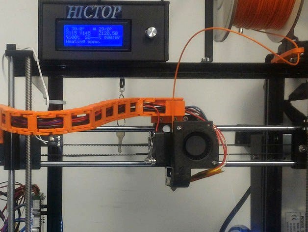
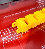
I had a problem with the wire mess on my new HICTOP and wanted a cable chain. Since I am always making changes to my printers I have to have an open chain and the ones that were presented here did not have an open side on the links. I prefer open links because you don't have to try an fish your cables in or out, you simply break the chain one link at a time and reassemble it around the cable.
So I redesigned the terminating mounts from http://www.thingiverse.com/thing:1357884 mounting the CableChain_XCarriage a little lower and opening up the side. I redid the Cable Chain_XStepper again to make it open and added a chain mount to the back incase I figure out how to transition to a chain that will connecto to the computer board.
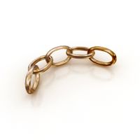
Finally, I took the cable chain from http://www.thingiverse.com/thing:511938 resized to fit the end mounts and group them into a set of 4 each ( your certainly will need more than one and extras come in handy)
So here you go.
Nov 2, 2016:
After some hours on the printer, I found I did not like the way the cable behaved at the X-Motor mount. I watched it for a while and realize I simply needed to make a simple change to get the cable to fold correctly. I had to make the chain end pointed so the links would fold back on the chain and therefore lay flatter. While I was at it I decided to also add a set of gate on the open side like I did for the X head mount.
Nov 13, 2016
After printing with the updated X-Motor Mount I kept noticing a POPing sound. I finally tracked this down to the shape of the point. I have converted this to a more filleted shape to make the transition easier. This form works much better. I have removed the V2 and update the original to avoid confusion. Also, I found that the chain rubbed against the lead screw when the X-head was all the way to the left. The fix for this is to simply invert the first link from the head. (The angle would normally be toward the back, except for the first link on the X-Head.
Dec 12, 2016
I was not entirely happy with the extruder/x carriage mount or the X-stepper motor mount. Some of the wires were flexing too much and I was worried that they may experience excessive strain because of it. Also, I was inspired by a YouTube video I saw, sorry I can't remember how to find it, where the circuit board case had a connector for a cable chain. So I have added support for a chain from the X-stepper motor to the circuit board case.
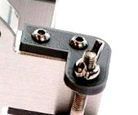
Finally, I redesigned the extruder/x-carriage mount to have a slot for the SN04 sensor cable and lowered the whole mount by about 8mm. This means that the screw holes for the mount are now part of the cable channel, but I added enough material to the channel to allow the screw heads to be fully counter-sunk.
Dec 13, 2016
Well, the testing of the electronics box went faster than expected so I have added it to this project. The project is now complete.
UPDATE Feb 27, 2017:
I have modified the case bottom to better handle the display cables, the USB jack and cable entry points. This version has all the entry points at the level of the board.
I also reduced the size of the cable chain mount on the top so you could use the same case with out the cable chain if you wish.
So I redesigned the terminating mounts from http://www.thingiverse.com/thing:1357884 mounting the CableChain_XCarriage a little lower and opening up the side. I redid the Cable Chain_XStepper again to make it open and added a chain mount to the back incase I figure out how to transition to a chain that will connecto to the computer board.
Finally, I took the cable chain from http://www.thingiverse.com/thing:511938 resized to fit the end mounts and group them into a set of 4 each ( your certainly will need more than one and extras come in handy)
So here you go.
Nov 2, 2016:
After some hours on the printer, I found I did not like the way the cable behaved at the X-Motor mount. I watched it for a while and realize I simply needed to make a simple change to get the cable to fold correctly. I had to make the chain end pointed so the links would fold back on the chain and therefore lay flatter. While I was at it I decided to also add a set of gate on the open side like I did for the X head mount.
Nov 13, 2016
After printing with the updated X-Motor Mount I kept noticing a POPing sound. I finally tracked this down to the shape of the point. I have converted this to a more filleted shape to make the transition easier. This form works much better. I have removed the V2 and update the original to avoid confusion. Also, I found that the chain rubbed against the lead screw when the X-head was all the way to the left. The fix for this is to simply invert the first link from the head. (The angle would normally be toward the back, except for the first link on the X-Head.
Dec 12, 2016
I was not entirely happy with the extruder/x carriage mount or the X-stepper motor mount. Some of the wires were flexing too much and I was worried that they may experience excessive strain because of it. Also, I was inspired by a YouTube video I saw, sorry I can't remember how to find it, where the circuit board case had a connector for a cable chain. So I have added support for a chain from the X-stepper motor to the circuit board case.
Finally, I redesigned the extruder/x-carriage mount to have a slot for the SN04 sensor cable and lowered the whole mount by about 8mm. This means that the screw holes for the mount are now part of the cable channel, but I added enough material to the channel to allow the screw heads to be fully counter-sunk.
Dec 13, 2016
Well, the testing of the electronics box went faster than expected so I have added it to this project. The project is now complete.
UPDATE Feb 27, 2017:
I have modified the case bottom to better handle the display cables, the USB jack and cable entry points. This version has all the entry points at the level of the board.
I also reduced the size of the cable chain mount on the top so you could use the same case with out the cable chain if you wish.
Similar models
thingiverse
free

Upgrade for Hictop 3DP-11 ATL by Klotzmando
...either the sn04 inductive sensor or the bltouch into similar designs, but first i have never had good luck...
thingiverse
free

Cable Chain Motor to Extruder head by SPWA
...x-axis on anet a8 printers. will probably work on similar machines. (update 28?10/2016 1.54pm the motor mount had a...
thingiverse
free

Anet A8 Z-axis cable chain by oh5gzr
...temperature sensor
extruder stepper motor cooling fan
extruder nozzle cooling fan
prepare yourself for some serious soldering! :)
thingiverse
free

Migbot i3 X-Axis Complete Cable Chain With Mounts by Reddrop
... can be found below:
cable chain: http://www.thingiverse.com/thing:11978
extruder clamp: http://www.thingiverse.com/thing:775684
thingiverse
free

Open Cable X-Axis Cable Chain Mount for Hictop Prusa i3 by jimmythekayaker
...oving the ends from the wiring harness.
i am currently using it with this cable chain: https://www.thingiverse.com/thing:611593
thingiverse
free

Ender 3 Electronics Case with Cable Chain Mount MKS Variant
... plan on upgrading to an mks gen l so i modified tt's case variant to also have the cable chain mount as with my other remix.
thingiverse
free

Zonestar P802M Cable Chain System by BirdJr
...(x stepper motor). used 29 chain links for the x-axis travel (extruder carriage). i would recommend re-leveling after installing.
thingiverse
free

Cable Chain Mounts for 10mm x 15mm Drag Chain
...mounts the chains.
4 - m3 x 8mm
2 - m3 x 12mm
1 - m3 x 10mm
2 - m5 x 15mm
updates:
01172020 - replaced chain mount for tool head.
thingiverse
free

I3 Clone Y-axis Chain Mounts by siskulous
...had gotten caught so many times that i had to replace them.
the mounts are designed to go with johnniewhiskey's cable chains.
thingiverse
free

X Axis Motor with cable chain mount by GeekGarage
...hain mount by geekgarage
thingiverse
updated the original bq x axis cable chain mount and ooznest x motor mount to fit together.
Klotzmando
thingiverse
free

Part for building a column of leds. by Klotzmando
...o form the leads of an led so that they may be soldered into column.
there will be more details as i finish parts of the project.
thingiverse
free

Hunter remote wall mount by Klotzmando
...ch may be screwed to the wall and holds the remote firmly but still allows for the remote to be removed and carried if necessary.
thingiverse
free

Adapter for opening in a ford fusion Hybrid by Klotzmando
...ch snaps into the dashboard mount on the back of the gps and then can be inserted into the opening on the back of the fill plate.
thingiverse
free

HICTOP LCD on the bottom by Klotzmando
... accessible (why did hictop leave that out?) and the sd slot is much cleaner and easier to "hit" when inserting a card.
thingiverse
free

Hotend Test stand by Klotzmando
... new file.
note: the extruder in the background is http://www.thingiverse.com/thing:589149. (giving credit where credit is due)
thingiverse
free

Cheerson CX10 Quad copter box. by Klotzmando
...he package is clearly marked 0.25 inch (8mm) magnets.
so i brought the project into fusion 360 and changed the size of the holes.
thingiverse
free

Case top for the Mega R3 and Newhaven Display LCD. by Klotzmando
...e same case as the mega.
i started with http://www.thingiverse.com/thing:101617 as a base, then designed this to replace the top.
thingiverse
free

Case for Waveshare 5inch HDMI LCD V2 and PI 2 by Klotzmando
...parts on my printrbot.
note:
just like my other waveshare project, this case will not work with the 5inch display from adafruit.,
thingiverse
free

Waveshare 5inch HDMI LCD (B) Simple Case by Klotzmando
...a 3d printable image of the lcd and the connectors in case you want check you printer accuracy to mine before you build the case.
thingiverse
free

30mm Fan Adapter for Rostock Max V2 by Klotzmando
...the e3d, using the proper squirrel cage fan. so i created this adapter to allow me to use the 30mm fan with the existing coolers.
Hictop
thingiverse
free

Hictop - Adjustable z Endstop by ptk21
...hictop - adjustable z endstop by ptk21
thingiverse
adjustable z endstop for hictop
thingiverse
free

Hictop 3d LCD Befestigung by festus402
...hictop 3d lcd befestigung by festus402
thingiverse
hictop 3d lcd befestigung
thingiverse
free

Cable chain HICTOP by Insani3D
...cable chain hictop by insani3d
thingiverse
iniciando la modificación de nuestra hictop, se diseña una eslabón a medida.
thingiverse
free

hictop y belt mount by polpetras
...hictop y belt mount by polpetras
thingiverse
hictop aluminum prusa y belt mount
thingiverse
free

Pen Holder for Hictop ender by basolur
...pen holder for hictop ender by basolur
thingiverse
this is a simple pen holder to use a hictop ender as a plotter.
thingiverse
free

remix for hictop mount by chibi_hero
...iverse
edit. made recesses for mounting deeper.
remixed this with http://www.thingiverse.com/thing:1323225
for my hictop 3dp-11.
thingiverse
free

Hictop 3DP-17 Parts by Adranovik
...hictop 3dp-17 parts by adranovik
thingiverse
printed parts for the hictop prusa eds-17 with auto level
thingiverse
free

Hictop xaxis clamp by Gen0idea
...oken x-axis belt clamp on the hictop printer.
printed in a different colour to the original to differentiate it as a replacement.
thingiverse
free

Hictop xaxis clamp by Gen0idea
...oken x-axis belt clamp on the hictop printer.
printed in a different colour to the original to differentiate it as a replacement.
thingiverse
free

Hictop i3 RAMPS Board Cover
...hictop i3 ramps board cover
thingiverse
cover for the stock ramps 1.3 board on the hictop i3 clone (2015 model).
3Dp
turbosquid
$15

ELEPHANT / / 3DP Animation Studio
... available on turbo squid, the world's leading provider of digital 3d models for visualization, films, television, and games.
turbosquid
$15

GOAT / / 3DP Animation Studio
... available on turbo squid, the world's leading provider of digital 3d models for visualization, films, television, and games.
turbosquid
$100

Gandhi Salt March 3DP
...ds, dxf, lwo, obj, wrl, x, c4d, fbx, 3dm, blend, lxo, and dae on turbosquid: 3d models for games, architecture, videos. (1447208)
3d_export
free
z-morph 3dp rear hook opt lasers
...also accessible on:<br>to find out more about the functionality of laser 3d printers, take a look at the following webpage:
3d_export
free
cnc 3dp laser engraving head opt lasers
...n also be found for free at:<br>if you want to take a look at the specifications of this laser head, please visit the link:
3d_export
free
cnc 3dp laser nozzle for 2w laser opt lasers
...logy that gave birth to cutting and engraving laser heads this laser nozzle was designed for, read the article in the link below:
3d_export
free
z-morph 3dp front hook opt lasers
...k is also available from:<br>to find out more about the 3d laser printer engraver technology, you can visit the link below:
3d_export
free
z-morph 3dp 6w engraving laser head
...e via:<br>if you want to learn the specifications of the 6w opt lasers cutting and engraving laser head, visit the website:
3d_export
$5

katar
...occlusion, curvature, world space normals, thickness, position.<br>fbx, obj, blend, 3dp 3ds, glb, ply, stl, usdc, x3d, mtl, dae,...
thingiverse
free
Robotics Feed 3DP
...ector-2
side wall extrusion 3dp connector-2
bevel box -1
l dt connector 1-2
l dt connector 2-2
arc and back plate 3dp connector-1
Chain
archibase_planet
free
Chain
...chain
archibase planet
chain chain link chain loop
chain n020708 - 3d model (*.gsm+*.3ds) for interior 3d visualization.
3d_export
$5

chain
...chain
3dexport
3d model chain
3d_export
$5

chain
...chain
3dexport
chain. obj,fbx,blend
archibase_planet
free

Chain
...se planet
chain circuit catena
chain - archicad parametrical gdl 3d model (*.gsm). regulation of the length, curvature and angle.
archibase_planet
free
Chain
...n
archibase planet
chain circuit catena
chain - archicad parametrical gdl 3d model(*.gsm). regulation of the length and angle xyz
3d_ocean
$5

Chain
...chain
3docean
3d models chain design elements
3d models, design elements
3d_ocean
$5

Chain
...chain
3docean
3d models chain design elements
3d models, design elements
turbosquid
$10
Chain
...hain
turbosquid
royalty free 3d model chain for download as on turbosquid: 3d models for games, architecture, videos. (1329200)
turbosquid
$9

chain
...hain
turbosquid
royalty free 3d model chain for download as on turbosquid: 3d models for games, architecture, videos. (1549461)
turbosquid
$2
Chain
...hain
turbosquid
royalty free 3d model chain for download as on turbosquid: 3d models for games, architecture, videos. (1148668)
Cable
3d_export
free

Cables
...cables
3dexport
cables for your purposes
3d_export
free
cable belt for cable organization
...ze your cables in 3d printers. it will bend only to one direction. the area to put the cables per piece is aprox. 1,6cmx2,6cmx1cm
3d_ocean
$16
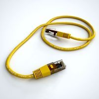
Ethernet Cable
...ethernet cable
3docean
cable computer electronics ethernet internet network connected
ethernet cable 3d model
3d_export
$65

cable
...cable
3dexport
simple rendering of the scene file
turbosquid
$14

Cable
...l cable for download as ma, max, fbx, 3ds, gltf, obj, and stl on turbosquid: 3d models for games, architecture, videos. (1631358)
3ddd
$1
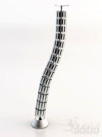
Cable Cover
...cable cover
3ddd
кабель
vertebra passacavo - cable cover
max + vray 2.20.03
3d_export
$15
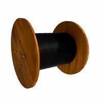
Cable reel
...without cable. textures 4k 4096x4096 targa, png, jpeg.<br>number of polygons without cable: 2896<br>with cable: 35328
3d_export
$7

short cable
...short cable
3dexport
rubber cord. very detailed. cable thickness: 2.55 mm total length: 55mm
3d_export
$5

USB CABLE
...usb cable
3dexport
turbosquid
$25

cable clip
...squid
royalty free 3d model cable clip for download as sldpr on turbosquid: 3d models for games, architecture, videos. (1232374)
11
turbosquid
free

PROTOTYPE WARRIOR (11 of 11)
... available on turbo squid, the world's leading provider of digital 3d models for visualization, films, television, and games.
3ddd
$1

11
...11
3ddd
мойка
полигональное моделирование
turbosquid
$25

11
... available on turbo squid, the world's leading provider of digital 3d models for visualization, films, television, and games.
3ddd
$1

Bed 11
...bed 11
3ddd
постельное белье
bed 11
3ddd
$1

Pozzoli 11
...pozzoli 11
3ddd
pozzoli , круглый
итальянский столик pozzoli
модель 11
design_connected
$9

ND0410-11
...nd0410-11
designconnected
house doctor nd0410-11 computer generated 3d model.
3d_export
$12

iphone 11
...iphone 11
3dexport
iphone 11 model with exact dimensions of 150.9 mm by 75.7 mm.
3d_export
$29

iphone 11 case 11
...en the scene. units: centimeters. file formats: blender obj fbx -stl -dea info poly/verts: iphone 11 case polys: 3609 verts: 3808
design_connected
$27

Domino 11
...domino 11
designconnected
zanotta domino 11 computer generated 3d model. designed by progetti, emaf.
design_connected
$27

Kilt 11
...kilt 11
designconnected
zanotta kilt 11 computer generated 3d model. designed by progetti, emaf.
Open
3d_export
free
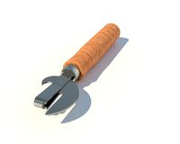
Opener
...r
3dexport
3d model of can opener. its my first work, if u can please show me my mistakes. this 3d model was created in autocad.
3d_export
free
Cap opener
...cap opener
3dexport
handy cap opener, more files/formats here:
3ddd
$1
Кресло, Open Oreon.
...кресло, open oreon.
3ddd
open , oreon
кресло, open oreon.
3d_ocean
$4
Open Book
...r interior max mental model open ray reading shelf text vray
open hardcover book with unique texture map on front and back cover.
turbosquid
$6
Opening Flag
...squid
royalty free 3d model opening flag for download as c4d on turbosquid: 3d models for games, architecture, videos. (1593555)
turbosquid
$10

Open book
...
royalty free 3d model open book for download as skp and obj on turbosquid: 3d models for games, architecture, videos. (1690781)
turbosquid
$2

bottle opener
...lty free 3d model bottle opener for download as blend and obj on turbosquid: 3d models for games, architecture, videos. (1621201)
turbosquid
$24

Bottle Opener
...free 3d model bottle opener for download as max, obj, and fbx on turbosquid: 3d models for games, architecture, videos. (1300948)
turbosquid
$20
Open Box
...yalty free 3d model open box for download as ma, obj, and fbx on turbosquid: 3d models for games, architecture, videos. (1481218)
3d_export
$20

bank vault open
...bank vault open
3dexport
bank vault open
Set
archibase_planet
free

Setting
...setting
archibase planet
setting cover place setting
setting - 3d model (*.gsm+*.3ds) for interior 3d visualization.
archibase_planet
free
Setting
...setting
archibase planet
setting place setting cover
setting - 3d model (*.gsm+*.3ds) for interior 3d visualization.
archibase_planet
free

Setting
...setting
archibase planet
setting place setting cover
setting - 3d model (*.gsm+*.3ds) for interior 3d visualization.
3d_export
$8

decorative set mens set
...decorative set mens set
3dexport
decorative set men's set
archibase_planet
free
Set
...anet
set kitchen ware kitchen set kitchen tools
set kitchen tools n281114 - 3d model (*.gsm+*.3ds) for interior 3d visualization.
archibase_planet
free
Set
...set
archibase planet
beer set bar equipment
beer set - 3d model for interior 3d visualization.
archibase_planet
free

Set
...set
archibase planet
cover place setting
set - 3d model (*.gsm+*.3ds) for interior 3d visualization.
archibase_planet
free

Set
...set
archibase planet
kitchen set kitchen ware
set - 3d model (*.gsm+*.3ds) for interior 3d visualization.
archibase_planet
free
Set
...set
archibase planet
set cup glass kitchen ware
set - 3d model (*.gsm+*.3ds) for interior 3d visualization.
archibase_planet
free

Set
...set
archibase planet
flatware cover place setting
set n311210 - 3d model (*.gsm+*.3ds) for interior 3d visualization.