Thingiverse
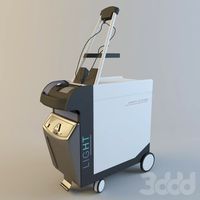
Nimble Gnu - System to Adapt the Zesty Nimble Extruder to a Prometheus V2 Hotend Mounted to a SeeMeCNC Balljoint Effector Platform with Accelerometer Probe PCB by slonold
by Thingiverse
Last crawled date: 3 years ago
Overview:
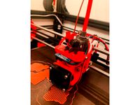
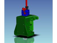
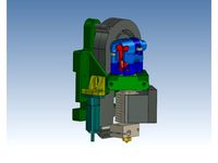
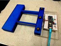
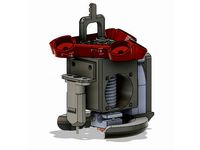
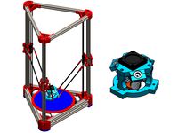
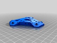
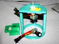
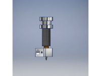
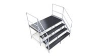
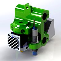
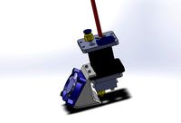
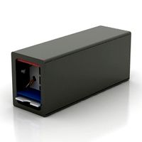
A system to adapt the Zesty Technology Remote Direct Drive Extruder to a Prometheus V2 Hotend via a SeeMeCNC Accelerometer Probe PCB and Ball Joint Effector Platform. Straps are used to retain the whip connector and there are a pair of 3mm auxiliary holes at each pillar for mounting items such as Berd Air System tubing or a probe etc.
The mounting system makes use of the Nimble to firmly seat the PTFE tubing in the bottom of the hotend barrel. Consequently, "setting" the PTC fitting in the hot end is not necessary which avoids narrowing the PTFE lumen at this point.
If you are interested in a Nimble-Prometheus-Ball Joint Platform setup without the Accelerometer please leave a comment and i will make an option for that sooner than later. In the interim, you could use this system without the Accelerometer PCB provided you place a little spacer between the bottom of the Guide Bushing and the top of the Prometheus to make up the vertical height (~1.7mm) of the absent board.
Required Parts:
M4 x 12 to 16mm button head or socket head cap screws to mount effector platform. QTY 3.Note: Button heads are recommended if using standard Rostock Max v2 fan shrouds.
M4 x 25mm button head or socket head cap screws to secure the Cap. QTY 3.
M3 x 6 to 10mm screws to affix the accelerometer board. QTY 3.Note: Nylon recommended to avoid shorting LED pads.
~ 60mm length of 4mm OD x 1.8 to 2.0mm ID PTFE tubing.
Recommended Tools:
M4 x 0.7 Tap
M3 x 0.5 Tap
4mm(#21) Drill - to size 4mm holes in Cap, Clamp Plate and Centre Plate
3.3mm (#30) Drill to size holes for tapping the M4 threads in the Stand Off
3mm (#31) Drill to size 3mm holes in Cap and Clamp Plate
2.4mm (3/32) Drill to clean out holes for tapping the accelerometer Clamp Plate
Drill bits +/- 4mm(#21) to size Guide Bushing bore to suit your PTFE tube size
1/2" half round file for fine tuning holes and slots to fit hot end
A half inch or similar half round file for finishing and sizing
Sharp knife or razor to trim PTFE tubing
Metal Saw to cut M3 Bolt
Variable Speed Hand Drill Motor
A small jewelers screw driver or blunt probe to install the straps.
Hex driver (Allen) keys to suit your selected fasteners.
Method of measuring hot end barrel depth
Prometheus Mount
Stand Off Sizing
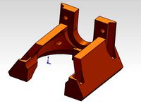
Decide if you will assemble the platform with the ball joint "barbells" on the bottom or top. Bottom orientation will allow shorter (and presumably stiffer) stand offs for a given amount of protrusion below the axis but will place the fan shrouds closer to the bed surface.
For the nozzle size and nut-nozzle zone setup of your Prometheus, decide how much protrusion below the platform you want.Note: Leave enough clearance for the fan shrouds and ball end arms to clear the bed clips!!
For the arrangement determined above, measure the distance from the top of the platform to the upper edge of the lower groove of the hot-end. This distance (in mm) with be the size/filename of the Stand Off model.
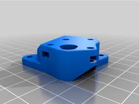
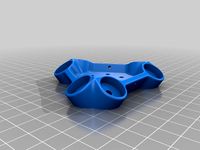
Components to Print: Prometheus Mount
one of the Standoffs_XXmm from the StandOffs_32_55mm.zip file
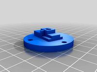
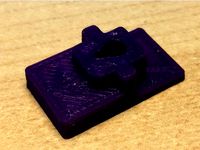
Centre_Plate_1
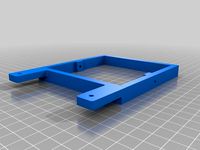
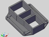
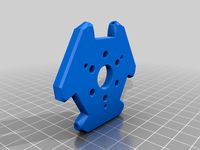
Nimble_Gnu_Clamp_Plate_71210_Accel_PrometheusNote: ABS recommended for these three parts for ease of post print sizing and natural lubricity for sliding into hotend grooves.
Assembly Instructions: Prometheus Mount
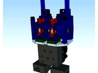
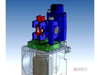
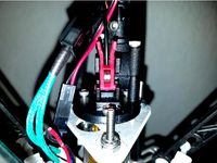
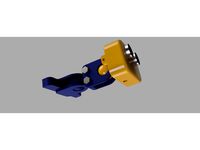
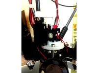
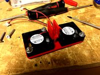
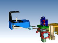
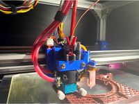
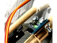
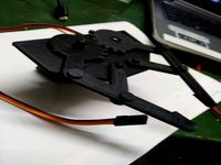
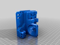
Considerations for assembling the Accelerometer PCB and Prometheus HotendNote that the arrangement of the heater block wiring to the accelerometer plate is such that the wires run up the left side of the hotend when looking down on it from the top and with the fan positioned away from you. See the various photos. The orientation of the cap to accelerometer PCB and the Nimble to the cap is fixed as also is the Clamp Plate to the accelerometer PCB. In order to have the breech block oriented to the front of the machine and the fan positioned towards the back (Z tower), the orientation shown in the photos must be followed. Other orientations may be possible by mirroring the Cap and/or the Clamp Plate before slicing.
When preparing to solder the fan connector headers avoid "pinching" the the pins together for retention. One of the heater wires will likely want to run right between them.
Providing a little (~1cm) slack in the heater and thermistor wires will allow disassembly of the Hotend without undue strain on them.
Through drill the large holes in the Clamp and Centre Plates ONLY to 4mm.
Through drill the holes in the Standoff to 3.3mm to size them for tapping.
Tap holes in Standoff from each end with the M4 tap.Note: Tap deep enough ensure that the M4 bolts will fully seat.
Through drill the small holes in the Clamp Plate to 2.4mm to size them for tapping.
Tap the small holes in the Clamp Plate with the M3 tap.
Ensure upper and lower surfaces of the the plates are free of swarf from drilling and tapping.
Relieve edges and finish slots in the Clamp Plate and Standoff to 12mm and 16mm and the centre hole of the Centre Plate to 16mm.Note: Fit of the Standoff and Clamp Plate into hot-end grooves should be snug but ensure that the Hotend seats fully into slots and that no more than a gentle squeeze is required to bring the bolt holes into alignment.
Slide and fully seat the Standoff into the lower groove of the hotend.
Place the Centre Plate over the top of the Hotend and onto the Clamp Plate.
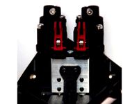
Clock the Clamp Plate as shown to accommodate LED, thermistor and fan wiring.
Slide and fully seat the Clamp Plate into upper groove of Hotend.
Note: It is not necessary to "seat" the PTC connector, it can be left loose. The Nimble will hold the PTFE tube firmly at the bottom of the Hotend barrel.
Ensure Accelerometer PCB fits flatly and easily into the recess in the Clamp Plate.
Temporarily install 4mm x 25mm screws through top of Clamp Plate into Standoff to ensure alignment of Clamp Plate.
Then firmly snug down 3mm screws to secure Accelerometer PCB.
Ensure soldered wires do not protrude more than 2mm above the PCB.
Arrange fan wires as shown in order to clear Cap.
Nimble Adapter
Components to Print: Nimble Adapter
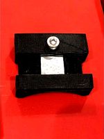
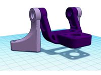
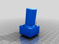
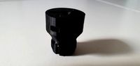
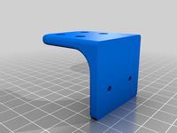
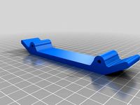
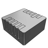
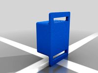
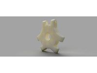
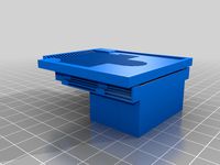
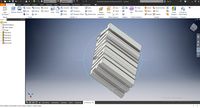
Nimble_Gnu_Cap_Prometheus_71210_Accel_Rev1Notes:PETG is recommended for strength of thin sections and thread robustness.
Best printed upside down (as shown in stl model).
Support for the countersink holes is recommended
Set xy support clearance to at least 0.3mm to maintain countersink clearance for the screw heads.
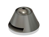
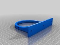
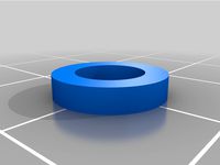
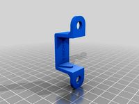
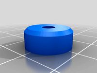
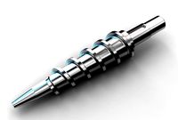
Guide_Bushing_Prometheus_Rev1Note: ABS recommended for ease of post print sizing and natural lubricity for passing PTFE tubing.
Strap QTY 2Note: TPU (NinjaFlex) recommended - you will likely get a much better result after installing the Nimble!
Assembly Instructions: Nimble Adapter
Trim ONE of the 40mm bolts that came with the Nimble to 35-37mm.
Through drill the large holes in the Cap to 4mm and ensure bolt heads fit freely in the countersinks.
Through drill the small holes in the Cap to 2.4mm to size them for tapping.
Tap the small holes in the Cap with the M3 tap.
Ensure all surfaces are free of swarf from drilling and tapping and that the centre hole of the cap is free of protrusions.
Square one end of the PTFE tube and chamfer the OD slightly.Note: Be sure to thoroughly clean the PTFE tubing of any fragments after cutting or shaping it. You do not want discover any unmelted shards in the tip of a small nozzle because by the time you excavate them, your sense of humor will be long gone...
Drill out the bore of the guide bushing so that your PTFE tube passes smoothly through it with a little force. The PTFE tubing should NOT be loose in the Guide Bushing.
Size the OD of the Guide Bushing so that it passes just freely through the centre hole of the cap.Note: You may want to employ the poor person's lathe for this purpose.
Measure the depth of the barrel in the hot end and the length of the PTFE tube.
Insert the squared and tapered end of the PTFE tube into the hot end barrel and seat it firmly.
Measure amount of PTFE tube protruding and verify tube is fully seated in the bottom of the Hotend barrel.
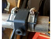
Install the two straps (can be done once Hotend mounted in printer so these could be your first print).Note: Judicious use of a small screw driver and a fingernail will avoid bloodletting and savagery.
Install the cap with the M4 x 25mm bolts.
Place the Guide Bushing over the PTFE tubing and seat it on top of the hot end.
Set the Groove Mount Adapter on top of the Guide Bushing. It should sit flat against the top of the Cap. Shorten the Guide Bushing from the Bottom if necessary.
The height of the top of the Guide Bushing should be just below the height of the rear locking tang (drive end) of the Groove Mount Adapter.
The smaller diameter "pin" of the Guide Bushing should fit snugly into the upper part of the Groove Mount Adapter.
While firmly pressing the PTFE tube into the bottom of the Hotend barrel , trim the PTFE tubing so that it slightly protrudes above the top of the Guide Bushing (0.3mm or about the width of a razor blade).
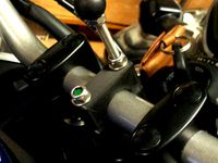
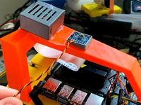
Mount the Nimble. Use the 40mm bolt with the Sleeve Clamp (or a 3mm spacer for fit testing without the drive cable) to avoid damaging the Accelerometer PCB.
Gentle tightening of the Nimble Mounting bolts should cause the Nimble to seat squarely on the Groove Mount Adapter and the entire body of the Nimble should seat squarely on the top of the Cap.
The PTFE tube should contact the bottom of the filament guide groove on centre without distortion. Re-trim the PTFE tube if necessary.Note: If you cut it twice and it is "still to short", START AGAIN with a new piece of tubing. You do not want the PTFE tube to be able to move vertically re the dread filament jam at the bottom of the barrel...
Once satisfied with the fit, snug down the Nimble mounting bolts.
Install Hotend in printer, strap down the whip.
Remember to revisit your slicer retraction settings. It is a whole new world without the Bowden tube.
A system to adapt the Zesty Technology Remote Direct Drive Extruder to a Prometheus V2 Hotend via a SeeMeCNC Accelerometer Probe PCB and Ball Joint Effector Platform. Straps are used to retain the whip connector and there are a pair of 3mm auxiliary holes at each pillar for mounting items such as Berd Air System tubing or a probe etc.
The mounting system makes use of the Nimble to firmly seat the PTFE tubing in the bottom of the hotend barrel. Consequently, "setting" the PTC fitting in the hot end is not necessary which avoids narrowing the PTFE lumen at this point.
If you are interested in a Nimble-Prometheus-Ball Joint Platform setup without the Accelerometer please leave a comment and i will make an option for that sooner than later. In the interim, you could use this system without the Accelerometer PCB provided you place a little spacer between the bottom of the Guide Bushing and the top of the Prometheus to make up the vertical height (~1.7mm) of the absent board.
Required Parts:
M4 x 12 to 16mm button head or socket head cap screws to mount effector platform. QTY 3.Note: Button heads are recommended if using standard Rostock Max v2 fan shrouds.
M4 x 25mm button head or socket head cap screws to secure the Cap. QTY 3.
M3 x 6 to 10mm screws to affix the accelerometer board. QTY 3.Note: Nylon recommended to avoid shorting LED pads.
~ 60mm length of 4mm OD x 1.8 to 2.0mm ID PTFE tubing.
Recommended Tools:
M4 x 0.7 Tap
M3 x 0.5 Tap
4mm(#21) Drill - to size 4mm holes in Cap, Clamp Plate and Centre Plate
3.3mm (#30) Drill to size holes for tapping the M4 threads in the Stand Off
3mm (#31) Drill to size 3mm holes in Cap and Clamp Plate
2.4mm (3/32) Drill to clean out holes for tapping the accelerometer Clamp Plate
Drill bits +/- 4mm(#21) to size Guide Bushing bore to suit your PTFE tube size
1/2" half round file for fine tuning holes and slots to fit hot end
A half inch or similar half round file for finishing and sizing
Sharp knife or razor to trim PTFE tubing
Metal Saw to cut M3 Bolt
Variable Speed Hand Drill Motor
A small jewelers screw driver or blunt probe to install the straps.
Hex driver (Allen) keys to suit your selected fasteners.
Method of measuring hot end barrel depth
Prometheus Mount
Stand Off Sizing
Decide if you will assemble the platform with the ball joint "barbells" on the bottom or top. Bottom orientation will allow shorter (and presumably stiffer) stand offs for a given amount of protrusion below the axis but will place the fan shrouds closer to the bed surface.
For the nozzle size and nut-nozzle zone setup of your Prometheus, decide how much protrusion below the platform you want.Note: Leave enough clearance for the fan shrouds and ball end arms to clear the bed clips!!
For the arrangement determined above, measure the distance from the top of the platform to the upper edge of the lower groove of the hot-end. This distance (in mm) with be the size/filename of the Stand Off model.
Components to Print: Prometheus Mount
one of the Standoffs_XXmm from the StandOffs_32_55mm.zip file
Centre_Plate_1
Nimble_Gnu_Clamp_Plate_71210_Accel_PrometheusNote: ABS recommended for these three parts for ease of post print sizing and natural lubricity for sliding into hotend grooves.
Assembly Instructions: Prometheus Mount
Considerations for assembling the Accelerometer PCB and Prometheus HotendNote that the arrangement of the heater block wiring to the accelerometer plate is such that the wires run up the left side of the hotend when looking down on it from the top and with the fan positioned away from you. See the various photos. The orientation of the cap to accelerometer PCB and the Nimble to the cap is fixed as also is the Clamp Plate to the accelerometer PCB. In order to have the breech block oriented to the front of the machine and the fan positioned towards the back (Z tower), the orientation shown in the photos must be followed. Other orientations may be possible by mirroring the Cap and/or the Clamp Plate before slicing.
When preparing to solder the fan connector headers avoid "pinching" the the pins together for retention. One of the heater wires will likely want to run right between them.
Providing a little (~1cm) slack in the heater and thermistor wires will allow disassembly of the Hotend without undue strain on them.
Through drill the large holes in the Clamp and Centre Plates ONLY to 4mm.
Through drill the holes in the Standoff to 3.3mm to size them for tapping.
Tap holes in Standoff from each end with the M4 tap.Note: Tap deep enough ensure that the M4 bolts will fully seat.
Through drill the small holes in the Clamp Plate to 2.4mm to size them for tapping.
Tap the small holes in the Clamp Plate with the M3 tap.
Ensure upper and lower surfaces of the the plates are free of swarf from drilling and tapping.
Relieve edges and finish slots in the Clamp Plate and Standoff to 12mm and 16mm and the centre hole of the Centre Plate to 16mm.Note: Fit of the Standoff and Clamp Plate into hot-end grooves should be snug but ensure that the Hotend seats fully into slots and that no more than a gentle squeeze is required to bring the bolt holes into alignment.
Slide and fully seat the Standoff into the lower groove of the hotend.
Place the Centre Plate over the top of the Hotend and onto the Clamp Plate.
Clock the Clamp Plate as shown to accommodate LED, thermistor and fan wiring.
Slide and fully seat the Clamp Plate into upper groove of Hotend.
Note: It is not necessary to "seat" the PTC connector, it can be left loose. The Nimble will hold the PTFE tube firmly at the bottom of the Hotend barrel.
Ensure Accelerometer PCB fits flatly and easily into the recess in the Clamp Plate.
Temporarily install 4mm x 25mm screws through top of Clamp Plate into Standoff to ensure alignment of Clamp Plate.
Then firmly snug down 3mm screws to secure Accelerometer PCB.
Ensure soldered wires do not protrude more than 2mm above the PCB.
Arrange fan wires as shown in order to clear Cap.
Nimble Adapter
Components to Print: Nimble Adapter
Nimble_Gnu_Cap_Prometheus_71210_Accel_Rev1Notes:PETG is recommended for strength of thin sections and thread robustness.
Best printed upside down (as shown in stl model).
Support for the countersink holes is recommended
Set xy support clearance to at least 0.3mm to maintain countersink clearance for the screw heads.
Guide_Bushing_Prometheus_Rev1Note: ABS recommended for ease of post print sizing and natural lubricity for passing PTFE tubing.
Strap QTY 2Note: TPU (NinjaFlex) recommended - you will likely get a much better result after installing the Nimble!
Assembly Instructions: Nimble Adapter
Trim ONE of the 40mm bolts that came with the Nimble to 35-37mm.
Through drill the large holes in the Cap to 4mm and ensure bolt heads fit freely in the countersinks.
Through drill the small holes in the Cap to 2.4mm to size them for tapping.
Tap the small holes in the Cap with the M3 tap.
Ensure all surfaces are free of swarf from drilling and tapping and that the centre hole of the cap is free of protrusions.
Square one end of the PTFE tube and chamfer the OD slightly.Note: Be sure to thoroughly clean the PTFE tubing of any fragments after cutting or shaping it. You do not want discover any unmelted shards in the tip of a small nozzle because by the time you excavate them, your sense of humor will be long gone...
Drill out the bore of the guide bushing so that your PTFE tube passes smoothly through it with a little force. The PTFE tubing should NOT be loose in the Guide Bushing.
Size the OD of the Guide Bushing so that it passes just freely through the centre hole of the cap.Note: You may want to employ the poor person's lathe for this purpose.
Measure the depth of the barrel in the hot end and the length of the PTFE tube.
Insert the squared and tapered end of the PTFE tube into the hot end barrel and seat it firmly.
Measure amount of PTFE tube protruding and verify tube is fully seated in the bottom of the Hotend barrel.
Install the two straps (can be done once Hotend mounted in printer so these could be your first print).Note: Judicious use of a small screw driver and a fingernail will avoid bloodletting and savagery.
Install the cap with the M4 x 25mm bolts.
Place the Guide Bushing over the PTFE tubing and seat it on top of the hot end.
Set the Groove Mount Adapter on top of the Guide Bushing. It should sit flat against the top of the Cap. Shorten the Guide Bushing from the Bottom if necessary.
The height of the top of the Guide Bushing should be just below the height of the rear locking tang (drive end) of the Groove Mount Adapter.
The smaller diameter "pin" of the Guide Bushing should fit snugly into the upper part of the Groove Mount Adapter.
While firmly pressing the PTFE tube into the bottom of the Hotend barrel , trim the PTFE tubing so that it slightly protrudes above the top of the Guide Bushing (0.3mm or about the width of a razor blade).
Mount the Nimble. Use the 40mm bolt with the Sleeve Clamp (or a 3mm spacer for fit testing without the drive cable) to avoid damaging the Accelerometer PCB.
Gentle tightening of the Nimble Mounting bolts should cause the Nimble to seat squarely on the Groove Mount Adapter and the entire body of the Nimble should seat squarely on the top of the Cap.
The PTFE tube should contact the bottom of the filament guide groove on centre without distortion. Re-trim the PTFE tube if necessary.Note: If you cut it twice and it is "still to short", START AGAIN with a new piece of tubing. You do not want the PTFE tube to be able to move vertically re the dread filament jam at the bottom of the barrel...
Once satisfied with the fit, snug down the Nimble mounting bolts.
Install Hotend in printer, strap down the whip.
Remember to revisit your slicer retraction settings. It is a whole new world without the Bowden tube.
Similar models
thingiverse
free
Crabby Cap Zesty Nimble SeeMeCNC HE280/Accelerometer Mount by slonold
...suit your ptfe tube size a half inch or similar half round file for finishing and sizing sharp knife...
thingiverse
free
Prometheus Mount for SeeMeCNC Rostock Ball Joint Platform +/- Accelerometer Option by slonold
...ive to the clamp plate like a clam shell.
be sure to seat bowden tube and insert ptc retainer before mounting accelerometer board
thingiverse
free
1.75" Tube Drill Guide
... 1/2-20 tap, to accept a thread-in drill guide/bushing. simply run a tap thru the print, and screw in the bushing of your choice.
thingiverse
free
1.5" Tube Drill Guide
...1/2-20 tap, to accept a thread-in drill guide/bushing. simply run a tap thru the print, and screw in the bushing of your choice.
thingiverse
free

Wanhao D9 Filament Guide Tube Holder by jamesarm97
...p fits over the d9 extruder top above the filament hole. the extruder cap will fit either the tube or a ptfe press fit connector.
thingiverse
free
Nimble V1 Chimera Mount plate by ZestyTech
...have the plate waterjet cut. you can then tap the mount holes for the nimble and have no need to use nuts to mount the 2 nimbles.
thingiverse
free
No drill Hailong Battery Mounting Plate by locnhinho
...lamp. 5/8" heat shink wrap should work.
please note that there is also an mount plate for use with the existent bottle hole.
thingiverse
free
Ormerod 2 Adapter to fit a Nimble V1 by ZestyTech
...uder you can buy, it has ample torque and can be mounted in multiple orientations.
the nimble is available from zesty technology.
thingiverse
free
Zesty Nimble adapter for TrickLaser Rostock groove mount by Schlauncha
... in the prints). single biggest improvement in performance i've seen out of any of the upgrades i've done to my rostock.
thingiverse
free
Nimble V1 Basic Adapter by ZestyTech
...uder you can buy, it has ample torque and is installable in multiple orientations.
the nimble is available at: https://zesty.tech
Slonold
thingiverse
free
Garmin 910XT 22mm Aerobar Extension Mount by slonold
...nt watch - note that strap does not have to be tight - spare your spring pins
adjust angle and fix by gently snugging set screws.
thingiverse
free
Crabby Cap Zesty Nimble SeeMeCNC HE280/Accelerometer Mount by slonold
... the ptfe tube should contact the bottom of the filament guide on centre without distortion. re-trim the ptfe tube if necessary.
thingiverse
free
Nimble Gimbal - Gimbaling Extruder Motor Mount for Zesty Nimble by slonold
...?). with the x60 i went with a 0.3mm nozzle and 0.2mm extrusion width, 3 perimeters, 0.125 layer height and 5 top/bottom layers.
thingiverse
free
Prometheus Mount for SeeMeCNC Rostock Ball Joint Platform +/- Accelerometer Option by slonold
...ive to the clamp plate like a clam shell.
be sure to seat bowden tube and insert ptc retainer before mounting accelerometer board
thingiverse
free

PanelDue 5" and Duet 2 Mounts for SeeMeCNC Rostock Max V2 by slonold
...phery of the onyx bed. some tape to hold the bed and template down will be your friend whilst you outline the bed plate cut out.
thingiverse
free
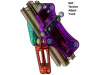
Belt Tension Adjust Truck for SeeMeCNC Ball Joint System and 1"x1" Extrusion by slonold
...ion truck at top, check tension at middle against fixed distance reference. tension at will!! gently snug screws when finished.
thingiverse
free
Nimble Gimbal For 2020 Delta Frame by quadcells
...i saw slonold's nimble gimbal and liked the idea. slonold did a great job on his design. i needed...
thingiverse
free
Zesty Nimble V2 Breech Replica by kulfuerst
...p3 - bearing offset by 0.3 mm i like slonold#39;s naming system and adapted it here. i have not...
Balljoint
thingiverse
free
BallJoint
...balljoint
thingiverse
a balljoint i designed to fit into a rest.
thingiverse
free
Balljoint by TheMadScientist
...balljoint by themadscientist
thingiverse
er, a joint - made from a ball...
thingiverse
free
HC-SR04 Balljoint Case with two balljoints by Divergentti
...h you can tighten with iso m5 screws. parts are similar for all joints, so, you may have many more joints with similar setup too.
thingiverse
free
balljoint led lamp by curious_pl
... make collection ... well. when i'll make more of them ;)
the tentacle monster block is for allowing splitting of balljoints.
thingiverse
free
BallJoint to Tube - Coupling by mechadense
...lectronic devices like garmin navigation computers to bike handlebars.
*.stl files:
for 22mm tubes.
the ball has 17.5mm diameter.
thingiverse
free
GU10 Socket for Balljoint Chain by jatha_wood_tec
...he ceramic gu10 sockets. the sleeve fits tightly around the socket.
the socket can be secured in place by some m3 bolts and nuts.
thingiverse
free
CW gestalt foot with balljoint by BenEccentricNormality
...design is reversible, depending on if you want a standard foot or the more two toed design that the combiner wars originals have.
thingiverse
free
GoPro Balljoint by MaksTinyWorkshop
...j'ai poncé un peu la boule et le réceptacle pour faciliter le mouvement mais ce n'est pas obligé quand on imprime en 0,1.
thingiverse
free
Articulated iPhone Case #balljoint by gnstech
...ion of sound. he is working on resizing and improving this model. we will update the files when the fully working model is ready.
thingiverse
free
![Tako-chan balljoint figure [Ninomae Ina'nis][Hololive][HololiveEN] by BRindustries](/t/8126049.jpg)
Tako-chan balljoint figure [Ninomae Ina'nis][Hololive][HololiveEN] by BRindustries
... printed in abs or similar filament, as more brittle filaments like pla might snap when attatching the parts onto the balljoints.
Zesty
3d_sky
free
ZESTY CHAIR by PLY COLLECTION
...zesty chair by ply collection
3dsky
http://www.plycollection.com/eng/chairs/zesty/
thingiverse
free

Zesty Nimble Mount for Tevo Tarantula
...esty nimble mount for tevo tarantula
thingiverse
this is my zesty nimble mount for the tevo tarantula which i used in our video.
thingiverse
free
Zesty Nimble Gimbal 3030
...zesty nimble gimbal 3030
thingiverse
remix for extrusion 3030
thingiverse
free
Gimble for Zesty Nimble on RailCoreII by Atalon
...coreii by atalon
thingiverse
i remixed this zesty nimble extruder motor gimble mount to fit kraeger's railcoreii 3d printer.
thingiverse
free
Zesty Nimble Mini Base by profdryoman
... zesty nimble.
see pictures for more info.
matches 3 mm outer / 2 mm inner ptfe.
second stl matches 4 mm outer / 2 mm inner ptfe.
thingiverse
free

Zesty Sidewinder stepper bracket mount 90 degrees
...ees bracket for mounting the stepper bracket for the zesty sidewinder on the original stepper mount on printers like the ender 3.
thingiverse
free
Hypercube Mount for Zesty Nimble v2 and Orion Piezo
...ion for the zesty nimble v2 and the orion piezo.
all other needed parts are from here https://www.thingiverse.com/thing:2617424.
thingiverse
free
Railcore Zesty Nimble Motor Mount
...lon locking nuts to hold it together. that is your choice. supports will help the holes to turn out better, but are not required.
thingiverse
free

Zesty Nimble and E3D v6 hotend mount for RailCore II 3D printer
...imble and e3d v6 hotend mount for the railcore ii 3d printer. it has guides for the nimble drive cable and teflon filament tube.
thingiverse
free
Zesty Adapter for Blue Eagle Labs Metal Delta by thystonius
...s are valid. also i highly recommend double checking your steps_per_mm. please do let me know if you find some better settings.
Seemecnc
thingiverse
free

Rostock hotend seemecnc by Wrangler
...rostock hotend seemecnc by wrangler
thingiverse
this thing was made to connect hotend seemecnc to rostock platform.
thingiverse
free

SeeMeCNC Keychain by johnoly99
...seemecnc keychain by johnoly99
thingiverse
no mas!
thingiverse
free

SeeMeCNC Rocket by johnoly99
...seemecnc rocket by johnoly99
thingiverse
no mas!
thingiverse
free
SeeMeCNC 3D Printer Model by ReginaFabricam
...seemecnc 3d printer model by reginafabricam
thingiverse
this is a model of the seemecnc orion delta 3d printer
thingiverse
free
SeeMeCNC H2 NamePlate (Blank) by CapperLabs
...seemecnc h2 nameplate (blank) by capperlabs
thingiverse
seemecnc h2 nameplate without any lettering autocad drawing and .stl
thingiverse
free

SeeMeCNC Plastic Bearings by johnoly99
...seemecnc plastic bearings by johnoly99
thingiverse
no mas!
thingiverse
free
Mosquito for SeeMeCNC Artemis by emoser
...and some rostock printeres.
you will need https://www.sliceengineering.com/collections/accessories/products/threaded-stem-adapter
thingiverse
free
SeeMeCNC EZstruder cooler by Disconnector
...r on my seemecnc rostock max was running very hot (like burn my hand hot!) so i designed a dual 40mm fan mount. all cool now :-)
thingiverse
free

SeeMeCNC H-1 90 Degree Clamp by johnoly99
...seemecnc h-1 90 degree clamp by johnoly99
thingiverse
seemecnc h-1 90 degree clamp
thingiverse
free

SeeMeCNC H-1 Table by johnoly99
...seemecnc h-1 table by johnoly99
thingiverse
no mas!
Prometheus
3ddd
$1
Prometheus
...ва
модель создана на основе существующего камина prometheus. компания focus. возможно использование в условиях интерьера и улицы.
3d_export
$10
Prometheus 3D Model
...prometheus 3d model
3dexport
spaceship
prometheus 3d model vladpobed 84868 3dexport
3d_export
$5

USS Prometheus NX-59650
...uss prometheus nx-59650
3dexport
the famous uss prometheus seen on star trek(voyager)
turbosquid
$190

Minoan Lines - Prometheus
...y free 3d model minoan lines - prometheus for download as skp on turbosquid: 3d models for games, architecture, videos. (1208485)
turbosquid
$2
Prometheus the Ceaseless Ember
...us the ceaseless ember for download as max, fbx, 3ds, and obj on turbosquid: 3d models for games, architecture, videos. (1633009)
3d_export
$30
hypersleepchamberaliens
...equipped with a holographic display that communicates with the prometheus#39; mainframe to monitor metabolic conditions to suspend cell function....
3d_export
$23

the last engineer 3d printing figurine
...artist decided to depict the last engineer whom the prometheus#39; crew awaked from hypersleep inside the engineer temple. the...
3d_sky
free

Prometheus
...earth fire firewood
the model is based on an existing fireplace prometheus. company focus. usable in the interior and the street.
thingiverse
free

Prometheus Ejuice Holder by travi
...prometheus ejuice holder by travi
thingiverse
prometheus statue from stalker cop.
for that special juice.
thingiverse
free
Prometheus(Edited) by HEROxCOMBAT
...prometheus(edited) by heroxcombat
thingiverse
for editing
Gnu
3d_export
$49

Wildebeest Connochaetes 3D Model
...wildebeest connochaetes 3d model 3dexport wildebeest connochaetes antelope gnou gnu black blue africa safari african mammal wild animal animals...
cg_studio
$40
Skins of wild animals3d model
...cgstudio rug carpet skin fur antilopa springbok kudu blue gnu bleskbok niala giraffe zebra .max - skins of wild...
3d_export
$40

Skins of wild animals 3D Model
...3dexport carpet rug fur skin antilopa springbok kudu blue gnu bleskbok niala giraffe zebra skins of wild animals 3d...
3d_export
$5

games equipment simple 3d style
...this model was created in software 'blender 3d' with gnu general public license (gpl, or free...
3d_export
$49

coat of arms of russia with golden eagle
...this model was created in software 'blender 3d' with gnu general public license (gpl, or free...
3d_export
$5

home sofa furniture cartoon simple style
...this model was created in software 'blender 3d' with gnu general public license (gpl, or free...
3d_export
$5

urban personal vehicle transport cartoon simple style
...this model was created in software 'blender 3d' with gnu general public license (gpl, or free...
3d_export
$5

chair ball furniture cartoon hi tech style
...this model was created in software 'blender 3d' with gnu general public license (gpl, or free...
3d_export
free

vr goggles headset simple
...this model was created in software 'blender 3d' with gnu general public license (gpl, or free...
3d_export
$5

sample model of split air conditioner outdoor box low poly
...this model was created in software 'blender 3d' with gnu general public license (gpl, or...
Nimble
3d_export
$10

toyota i-tril
...residents of small and medium-sized cities. a small and nimble three-seater electric car with a range of more than...
3d_export
$99

titanfall stryder
...survive a straight-up slugfest.<br>the stryder is an agile and nimble ***an, favouring speed and mobility over the other ***ans,...
3d_export
$25

Cartoon Zooba Nix Rigged Ready For Games
...'balanced'. on the character menu, she is described as “nimble and cunning”. nix is a very crafty fox that...
thingiverse
free
Nimble V1 and Nimble V2 on the E3D Toolchanger
...uder you can buy, it has ample torque and can be mounted in multiple orientations.
the nimble is available from zesty technology.
thingiverse
free
Nimble Inside by ZestyTech
...uder you can buy, it has ample torque and can be mounted in multiple orientations.
the nimble is available from zesty technology.
thingiverse
free
Mockup of the Dual Nimble aka Nimble C/C by ZestyTech
...uder you can buy, it has ample torque and can be mounted in multiple orientations.
the nimble is available from zesty technology.
thingiverse
free
Nimble V2 mount for Tevo TLM
...uder you can buy, it has ample torque and can be mounted in multiple orientations.
the nimble is available from zesty technology.
thingiverse
free
HevoRT Nimble V2 + Kryo mount
...hevort nimble v2 + kryo mount
thingiverse
this is a remix of miragec caridge to accommodate the nimble v2 and kryo
thingiverse
free
Nimble V2 mount for the BLV Cube
...uder you can buy, it has ample torque and can be mounted in multiple orientations.
the nimble is available from zesty technology.
thingiverse
free
Nimble Sidewinder V1.1 on a HEVO by ZestyTech
...er you can buy, it has ample torque and can be mounted in multiple orientations.
the nimbles are available from zesty technology.
Accelerometer
3d_export
$35

chevrolet camaro
...other 3d software. has car interior details; seat, pheromone, accelerometer a short video of this project has been uploaded...
3dfindit
free
Embedded Accelerometers
...embedded accelerometers
3dfind.it
catalog: te connectivity
thingiverse
free
Accelerometer Case by lakephall
...celerometer sensor face-down. the tabs on the side are meant to allow for half-inch hook and loop straps to hold down the sensor.
thingiverse
free
WIMUv3 Accelerometer Calibration Fixture by M_G
... be placed in a known position on the test apparatus to aid in the repeatable calibration of said accelerometer containing device
thingiverse
free
U-Bracket for GDX Accelerometer by vernier
...ernier
thingiverse
this bracket is used with the gdx accelerometer.
this bracket is designed to be used with a 1/4-20 screw/nut.
thingiverse
free
3D printed MEMS accelerometer by adamweld
... the device was envisioned to be simple and easy to understand while using the same operating principles as a mems accelerometer.
thingiverse
free

Tube Plate for GDX accelerometer by vernier
...be plate is used to mount the gdx accelerometer.
this plate (and the accompanying bracket) are designed around 1/4-20 fasteners.
thingiverse
free
Gyroscope / Accelerometer Mount by dgngdn
...ace by two nuts. the end is flexible so as to allow the mount to clip on a cylindrical object with outside diameter of about 8mm.
thingiverse
free

Box for gyro accelerometer board by robsteele
...by andy mark. it will require tapping 4 holes for #4 screws. the top parts has a hold for a 10-24 screw for holding the box down.
thingiverse
free
Donkeycar GY-521 accelerometer and gyro support
...his one:https://fr.aliexpress.com/item/1028067742.html
probably not the best. need a super quiet (stable with no spike) power in.
Effector
3d_ocean
$5

Radial Sound Effector
...e spheres will expand with your song. fully customisable, change the color, the size of the spheres or even put in different s...
3d_ocean
$12

3D Customizable Puzzle Set (16x10)
...mograph compatible (you can effect the pieces with mograph effector) - included also a non-mograph version with...
thingiverse
free
Effector by olo2000pm
...effector by olo2000pm
thingiverse
effector
thingiverse
free
CERAMBOT-Effector
...cerambot-effector
thingiverse
cerambot-effector
thingiverse
free

modulize effector by candyasdf
...ulize effector by candyasdf
thingiverse
mount things on effector with m3 screws
effector radius : 25.4mm
rod arm distance : 40mm
thingiverse
free
Delta Effector by zavier
...delta effector by zavier
thingiverse
delta effector with radial fan 50 and bltouch
thingiverse
free
D810 Effector by WhiteTiger13
...d810 effector by whitetiger13
thingiverse
this is d810 effector for d810 without autocalibration, and also cap for it.
thingiverse
free
Effector for Delta Printer
...effector for delta printer
thingiverse
effector for delta printer (3 color)
using diamond hotend
thingiverse
free
Delta effector magnetic by fpassos
...delta effector magnetic by fpassos
thingiverse
effector for e3dv6 hotend. i needed put the spheres (10mm) on the effector.
thingiverse
free
End Effector Gripper
...end effector gripper
thingiverse
end effector gripper
for a robotic arm
uses mg995 servo motor
Probe
turbosquid
$25
Probe
... available on turbo squid, the world's leading provider of digital 3d models for visualization, films, television, and games.
turbosquid
$35
Space Probe
...osquid
royalty free 3d model space probe for download as c4d on turbosquid: 3d models for games, architecture, videos. (1571168)
turbosquid
$15
Space Probe
...osquid
royalty free 3d model space probe for download as obj on turbosquid: 3d models for games, architecture, videos. (1314864)
turbosquid
$25

Robot Probe
...y free 3d model robot probe for download as fbx, obj, and dae on turbosquid: 3d models for games, architecture, videos. (1537490)
turbosquid
$1

Dental Probe
...e 3d model dental probe for download as ma, obj, fbx, and stl on turbosquid: 3d models for games, architecture, videos. (1312400)
turbosquid
$60
Police Probe
... available on turbo squid, the world's leading provider of digital 3d models for visualization, films, television, and games.
turbosquid
$9

Space probe
... available on turbo squid, the world's leading provider of digital 3d models for visualization, films, television, and games.
turbosquid
free

Cassini Probe
... available on turbo squid, the world's leading provider of digital 3d models for visualization, films, television, and games.
turbosquid
$70
parker solar probe
...3d model parker solar probe for download as jpg, max, and fbx on turbosquid: 3d models for games, architecture, videos. (1372573)
turbosquid
$85

Adams Probe 16
... available on turbo squid, the world's leading provider of digital 3d models for visualization, films, television, and games.
Hotend
thingiverse
free
hotend by fablab_lueneburg
...hotend by fablab_lueneburg
thingiverse
hotend model
thingiverse
free
Hotend for Graber
...hotend for graber
thingiverse
hotend complement pastes for graber printerhttps://youtu.be/0koxhnsuhdy
thingiverse
free
Hotend adapter by antaviana
...hotend adapter by antaviana
thingiverse
hotend adapter
thingiverse
free
hotend fan by mming1106
...hotend fan by mming1106
thingiverse
hotend fan
thingiverse
free

Hotend schema by ione
...hotend schema by ione
thingiverse
hotend project schema
thingiverse
free
Fabtotum XY Hotend holder for E3D Hotend
...s with integrated supports.
more for the project you can see here: https://kf-designs.com/2019/09/07/fabtotum-printer-conversion/
thingiverse
free
HotEnd Stand by onepointdiy
...tend, when you make your new hotend or repair your j-head or mg-plus hotend.
the hole of 16mm, please adjust using a reamer, etc.
thingiverse
free

fast magnetic hotend changer for Chimera Hotend by Draman
...chimera hotend !
and new basis (the hole from original is to small)
it is a remix form skimmy's fast magnetic hotend changer
thingiverse
free

Hotend Fan Adapter for MicroSwiss All Metal Hotend by jo_schi_man
...
thingiverse
little change for the hotend fan adapter to hold the microswiss all metal hotend (slightly longer and sharp edges).
thingiverse
free
Merlin Hotend by Alejanson
...merlin hotend by alejanson
thingiverse
this is a 1:1 drawing of the classic merlin hotend.
Pcb
3ddd
$1

GRAMERCY HOME - CARMELA ARMCHAIR 602.023-PCB
...gramercy home - carmela armchair 602.023-pcb
3ddd
gramercy home
gramercy home
carmela armchair
602.023-pcb
www.gramercy-home.ru
3d_export
$150
auto pcb board loder inspection machine
...auto pcb board loder inspection machine
3dexport
auto pcb board loder & inspection machine --> only step file
3d_export
$7
turning mechanism drawing pcb board turnover machine
...turning mechanism drawing pcb board turnover machine
3dexport
turning mechanism drawing pcb board turnover machine
turbosquid
$9

Stereo Jack 3.5mm for soldering to a PCB
... available on turbo squid, the world's leading provider of digital 3d models for visualization, films, television, and games.
3d_export
$5

LED Right Angled PCB Mounting
...m led. step and igus files. multiple led colors: blue, purple, red, green, and yellow. dimensions case w 4,5mm , h 7,3mm l 6,4mm.
3d_export
$20
automatic pcb loading and unloading dispensing test automatic line
...ment structure is very complex. it is a very practical equipment for smt industry. the equipment is mature application equipment.
3d_export
$18
an automatic line for fct function test of pcb
... drawings are downloaded, you can directly watch and edit the contents. welcome to download and learn from your favorite friends.
3d_export
$5
USB Micro B connector
...step and igus for 3d import into ecad tools, pcb footprints. added also a altium designer pcb component library...
3d_export
$15
plastic housing with dewalt battery holder
...case measures 155x106x60. inside the case there are two pcb of 130x98 and 98x42...
3d_export
$7
automatic packing line - packing sorting and stacking equipment line
...sorting and stacking equipment line 3dexport automatic packaging line<br>1. pcb board is manually placed from the placement position and...
Platform
archibase_planet
free
Platform
...rm
archibase planet
platform
platform stefano galli savio cerrato n040413 - 3d model (*.gsm+*.3ds) for exterior 3d visualization.
turbosquid
$4
Platform
...d
royalty free 3d model platform for download as max and fbx on turbosquid: 3d models for games, architecture, videos. (1363559)
3d_export
$5
WORKING PLATFORM
...working platform
3dexport
working platform 4000x3000x1500mm
turbosquid
$20
Platform
... available on turbo squid, the world's leading provider of digital 3d models for visualization, films, television, and games.
turbosquid
$9
Platform
... available on turbo squid, the world's leading provider of digital 3d models for visualization, films, television, and games.
turbosquid
$1
Platform
... available on turbo squid, the world's leading provider of digital 3d models for visualization, films, television, and games.
turbosquid
$1

Platform
... available on turbo squid, the world's leading provider of digital 3d models for visualization, films, television, and games.
turbosquid
$1

Platform
... available on turbo squid, the world's leading provider of digital 3d models for visualization, films, television, and games.
3d_ocean
$19
Drilling Platform
...rm for coastal areas. designed to perform drilling operations. include standart materials scene and v-ray scene with environment.
3d_export
$15
steel grill platform
...steel grill platform
3dexport
steel grill platform
V2
3d_export
free
Lamp v2
...lamp v2
3dexport
lamp v2 with solar panel
3d_export
$5

hammerhead v2
...hammerhead v2
3dexport
razer hammerhead v2 headphones, modeled in cinema 4d, render in corona
3d_export
$5

manometer v2
...manometer v2
3dexport
3d_export
$5

potato v2
...potato v2
3dexport
turbosquid
$52

Lifebuoys v2
...squid
royalty free 3d model lifebuoys v2 for download as fbx on turbosquid: 3d models for games, architecture, videos. (1560870)
turbosquid
$2

Mask v2
...turbosquid
royalty free 3d model mask v2 for download as stl on turbosquid: 3d models for games, architecture, videos. (1527741)
turbosquid
$20

Kitchen V2
...ty free 3d model kitchen v2 for download as max, obj, and fbx on turbosquid: 3d models for games, architecture, videos. (1155111)
turbosquid
$20

kengkod64-v2
... free 3d model kengkod64-v2 for download as 3dm, ztl, and stl on turbosquid: 3d models for games, architecture, videos. (1701415)
turbosquid
$19

Chair v2
...yalty free 3d model chair v2 for download as ma, obj, and fbx on turbosquid: 3d models for games, architecture, videos. (1693360)
turbosquid
$15
Table v2
...yalty free 3d model table v2 for download as ma, fbx, and obj on turbosquid: 3d models for games, architecture, videos. (1688743)
Extruder
3ddd
$1
Extruded Chair
...extruded chair
3ddd
extruded , tom dixon
inspired by tom dixon extruded chair
turbosquid
$2
3D Printer Extruder
...d
royalty free 3d model 3d printer extruder for download as on turbosquid: 3d models for games, architecture, videos. (1537359)
turbosquid
$1
Zombie extruded text
...oyalty free 3d model zombie extruded text for download as obj on turbosquid: 3d models for games, architecture, videos. (1322198)
turbosquid
$4
Extruder conical screw
...el extruder conical screw for download as sldpr, ige, and stl on turbosquid: 3d models for games, architecture, videos. (1524433)
turbosquid
$50
3d PRINTER - Extruder
... available on turbo squid, the world's leading provider of digital 3d models for visualization, films, television, and games.
3d_export
$5

world earth extrude map
...world earth extrude map
3dexport
3ddd
$1

Simply Elegant Extruded Tree Coffee Table Design
...ble by link studios. the silhouette of a tree is visible at one angle, extruded from the surface to create the support structure.
3d_export
$13
extruded table
...ed to give you the highest possible quality for up to 4k renders. there is no post-production used on any of the renders you see.
3d_export
$13

extruded chair
...for high-quality render results. no extra plugins are required for this model. lights and cameras are not included in the scenes.
3d_export
$13
extruded table 2
...for high-quality render results. no extra plugins are required for this model. lights and cameras are not included in the scenes.
Adapt
3d_export
$10
Adapter 3D Model
...adapter 3d model
3dexport
adapter
adapter 3d model mur 20260 3dexport
archive3d
free
Adapter socket 3D Model
...dapter socket adapter
adapter socket n090211 - 3d model (*.3ds) for interior 3d visualization.
archive3d
free
Adapter 3D Model
...ups pc equipment
adapter extron n180813 - 3d model (*.gsm+*.3ds) for interior 3d visualization.
turbosquid
$5
usb adapter
...royalty free 3d model usb adapter for download as ige and stl on turbosquid: 3d models for games, architecture, videos. (1582234)
turbosquid
$15
Power adapter
...free 3d model power adapter for download as max, obj, and fbx on turbosquid: 3d models for games, architecture, videos. (1510024)
turbosquid
$8
USB adapter
...e 3d model usb adapter for download as max, fbx, obj, and dwg on turbosquid: 3d models for games, architecture, videos. (1713542)
turbosquid
$30

adapter.3ds
... available on turbo squid, the world's leading provider of digital 3d models for visualization, films, television, and games.
turbosquid
$15
Nokia Adapter
... available on turbo squid, the world's leading provider of digital 3d models for visualization, films, television, and games.
turbosquid
$10
Nibra Adapter
...l nibra adapter for download as 3ds, obj, fbx, blend, and dae on turbosquid: 3d models for games, architecture, videos. (1381249)
turbosquid
$1
Adapter Netgear
... available on turbo squid, the world's leading provider of digital 3d models for visualization, films, television, and games.
System
archibase_planet
free
System
...m
archibase planet
fire alarm system fire alarm box
security light system - 3d model (*.gsm+*.3ds) for interior 3d visualization.
archibase_planet
free
Spider system
...stem spider glass system
spider system to fix glass stefano galli n050912 - 3d model (*.gsm+*.3ds) for interior 3d visualization.
3ddd
$1
Euforia System
...euforia system
3ddd
euforia
euforia system
3d_export
$50
Roof system Truss system 3D Model
...oof system truss system 3d model
3dexport
roof system truss truss stage
roof system truss system 3d model aleksbel 38970 3dexport
3ddd
$1
DVD System
...dvd system
3ddd
dvd , schneider
dvd system
design_connected
free

Seating system
...seating system
designconnected
free 3d model of seating system
3d_export
$5

solar system
...solar system
3dexport
solar system in c4d, with 8k nasa textures
3ddd
$1
Quanta System
...quanta system
3ddd
медицина
quanta system.
лазерное оборудование для медицинских центров
3d_export
$15
solar system
...nd the other the sun, the earth and the moon, the latter has an animation with camera movement included, the files are in spanish
3d_export
$14

missile system
...missile system
3dexport
Mounted
3d_export
free

mounting bracket
...mounting plate is the portion of a hinge that attaches to the wood. mounting plates can be used indoors, cabinetry and furniture.
turbosquid
$2

MOUNTING
... available on turbo squid, the world's leading provider of digital 3d models for visualization, films, television, and games.
turbosquid
free

Mounts
... available on turbo squid, the world's leading provider of digital 3d models for visualization, films, television, and games.
turbosquid
free

Mount Fuji
...fuji
turbosquid
free 3d model mount fuji for download as obj on turbosquid: 3d models for games, architecture, videos. (1579977)
3d_export
$5

Headphone mount LR
...headphone mount lr
3dexport
headphone mount l+r
turbosquid
$39

Mount rainier
...quid
royalty free 3d model mount rainier for download as fbx on turbosquid: 3d models for games, architecture, videos. (1492586)
turbosquid
$5

pipe mounting
...quid
royalty free 3d model pipe mounting for download as obj on turbosquid: 3d models for games, architecture, videos. (1293744)
turbosquid
$3

Mounting Tires
...uid
royalty free 3d model mounting tires for download as fbx on turbosquid: 3d models for games, architecture, videos. (1708511)
3d_export
$5

Magnetic GoPro Mount
...pro mount
3dexport
cool magnetic mount for gopro. allows you to mount the camera on flat metal surfaces and get exclusive shots.
turbosquid
$5

Stone Mount
...ty free 3d model stone mount for download as ma, obj, and fbx on turbosquid: 3d models for games, architecture, videos. (1370306)