Thingiverse
Neopixel Mini Cube
by Thingiverse
Last crawled date: 4 years, 2 months ago
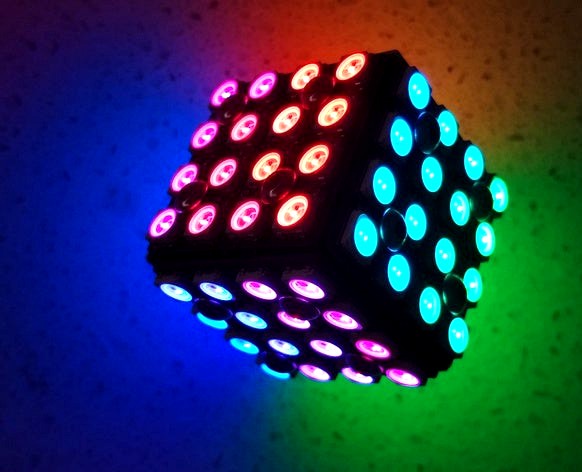
This mini cube is made up of six 4x4 WS2812B panels giving a total of 96 individually addressable RGB LEDs. Buried inside the cube is a ATTiny85 microcontroller powered by a 120mAh Lithium Ion battery. It also contains a mercury switch and a couple of transistors to turn the cube on. The cube switches itself off after displaying a series of animations.
Video
https://youtu.be/mVqQSdfhl90
Assembly
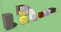
3D print the holder for the panels with supports and a raft. After you clean off the support and raft, drill out the holes with a 2.5mm drill and create a thread with a 3mm tap. Next you need to wire up the six WS2812B panels. Start with the four side panels. I used 0.5mm tinned copper wire. Each time you complete a panel, test it on the former and re-adjust the wires if necessary to get a good fit without straining the connections and also having the screw holes lined up. Connect fine insulated wire (I used wire-wrap wire) to the VCC, DIN, GND on the first side panel and VCC, DOUT, GND on the last side panel. Screw on the sides using M3 x 6 or M3 x 8 screws. Next connect the bottom VCC, DIN, GND to the VCC, DOUT, GND wires of the last side panel and screw it in-place. (See Sketch, it contains a wiring diagram showing how all the panels are ordered and how they need to be connected). For the top panel, connect the VCC, DOUT, GND to the VCC, DIN, GND wires of the first side panel. Add wires to VCC, DIN, GND of the top panel. These will ultimately be connected to the custom PCB.
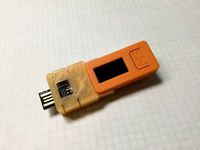
Eagle files have been included so that you can get the board manufactured or make it yourself. Mine was made using the Toner method. I have left small holes so that I could attach wires and connect the board to my Digispark Development System (https://www.thingiverse.com/thing:3975240). This allowed me to develop the software. In theory you shouldn't need to do this as you can just program the ATTiny85 and solder it to the board.
(Note: The picture of the V2 PCB shown above was my development board. The 1K5 resistor you see tacked on the board has been incorporated on the V3 board.)
The Sketch is included. To program the ATTiny85, I used my AVR programmer (https://www.thingiverse.com/thing:3882262) to burn a Digispark bootloader onto the chip and then programmed it using my Digispark development system.
Parts
6 x WS2812B 4x4 16-Bit Full Color 5050 RGB LED Lamp Panel Light
1 x ATTiny85 SMD
1 x 120mAh Lithium Ion battery
3 x 1M 0805 resistors
1 x 100K 0805 resistor
1 x 330R 0805 resistor
1 x 1K5 0805 resistor
2 x 0.1uF 0805 capacitors
1 x 100uf 10V 3528 Tantalum capacitor
1 x AO3401 P-Channel MOSFET SOT-23
1 x 2N3904 NPN Transistor SOT-23
1 x 0805 Red LED
1 x JST-PH-2-THM-RA socket
1 x 5mm mercury switch
Video
https://youtu.be/mVqQSdfhl90
Assembly
3D print the holder for the panels with supports and a raft. After you clean off the support and raft, drill out the holes with a 2.5mm drill and create a thread with a 3mm tap. Next you need to wire up the six WS2812B panels. Start with the four side panels. I used 0.5mm tinned copper wire. Each time you complete a panel, test it on the former and re-adjust the wires if necessary to get a good fit without straining the connections and also having the screw holes lined up. Connect fine insulated wire (I used wire-wrap wire) to the VCC, DIN, GND on the first side panel and VCC, DOUT, GND on the last side panel. Screw on the sides using M3 x 6 or M3 x 8 screws. Next connect the bottom VCC, DIN, GND to the VCC, DOUT, GND wires of the last side panel and screw it in-place. (See Sketch, it contains a wiring diagram showing how all the panels are ordered and how they need to be connected). For the top panel, connect the VCC, DOUT, GND to the VCC, DIN, GND wires of the first side panel. Add wires to VCC, DIN, GND of the top panel. These will ultimately be connected to the custom PCB.
Eagle files have been included so that you can get the board manufactured or make it yourself. Mine was made using the Toner method. I have left small holes so that I could attach wires and connect the board to my Digispark Development System (https://www.thingiverse.com/thing:3975240). This allowed me to develop the software. In theory you shouldn't need to do this as you can just program the ATTiny85 and solder it to the board.
(Note: The picture of the V2 PCB shown above was my development board. The 1K5 resistor you see tacked on the board has been incorporated on the V3 board.)
The Sketch is included. To program the ATTiny85, I used my AVR programmer (https://www.thingiverse.com/thing:3882262) to burn a Digispark bootloader onto the chip and then programmed it using my Digispark development system.
Parts
6 x WS2812B 4x4 16-Bit Full Color 5050 RGB LED Lamp Panel Light
1 x ATTiny85 SMD
1 x 120mAh Lithium Ion battery
3 x 1M 0805 resistors
1 x 100K 0805 resistor
1 x 330R 0805 resistor
1 x 1K5 0805 resistor
2 x 0.1uF 0805 capacitors
1 x 100uf 10V 3528 Tantalum capacitor
1 x AO3401 P-Channel MOSFET SOT-23
1 x 2N3904 NPN Transistor SOT-23
1 x 0805 Red LED
1 x JST-PH-2-THM-RA socket
1 x 5mm mercury switch
Similar models
thingiverse
free

Bladeless Fan by Elite_Worm
...parts. required parts: 1 x 1100kv brushless motor or similar i used a turnigy. 1 x standard esc. the...
grabcad
free

Resistor 1k5 1/8W
...resistor 1k5 1/8w
grabcad
resistor 1k5 1/8w eds for proteus ide
grabcad
free

Resistor 1k5 1/4W
...resistor 1k5 1/4w
grabcad
resistor 1k5 1/8w eds for proteus ide
thingiverse
free

Digispark Development System
...com/thing:3938405
animated matrix dicehttps://www.thingiverse.com/thing:3877685
star xmasshttps://www.thingiverse.com/make:414311
thingiverse
free

Logitech G29, G920, G27 Handbrake by thortazo
...this time i used an arduino board clone).
once you have completed your diy handbrake you'll have to screw it to your shifter.
thingiverse
free

OpenBCI Enclosure Box by ara
...on from a vcc pin on the openbci board with a 220ohm resister inline to drop the voltage since the led in the switch is only 2v2.
thingiverse
free

Logitech G25/ G27/ G29 Handbrake by Rafix095
...#39;t overheat anything, and be super careful not to bridge the resistor.
remixed from: https://www.thingiverse.com/thing:2772250
thingiverse
free

Digispark cherry mx single key "keyboard" by Ultrawipf
...ch will handle stuff like double and long presses for you.
simply connect the switch between gnd and pin 0 with some short wires.
thingiverse
free
Digispark HAT for M5StickC
...; p2
optional; jumper header & 2.54mm pin header connector(3pin)
[. . . ]
[123]
1:=nc
2:=digispark[5v_out]
3:=m5stick [5v_in]
thingiverse
free

2.4" 240 x 320 TFT clock with 3.7v lithium battery by mkchung22
...battery x 1
ds3231 rtc x 1
main switch x 1
push switch x 3
4.7k resistor x 4
reference link as below:https://youtu.be/ndcxs5iq6iy
Neopixel
thingiverse
free

NeoPixel Mount
...neopixel mount
thingiverse
geeetech a10m neopixel mount
thingiverse
free

neopixel clock by arradan
...neopixel clock by arradan
thingiverse
this is frame for neopixel clock with 60 led neopixel ring.
thingiverse
free

neopixel cover
...neopixel cover
thingiverse
a basic cover made for neopixel's using clear pla filament
thingiverse
free

Neopixel Cover
...neopixel cover
thingiverse
neopixel cover i made for a knight rider light bar build made in freecad.
thingiverse
free

Joseph Neopixel by ShimmyJ
...joseph neopixel by shimmyj
thingiverse
neopixel shifts colors
thingiverse
free

3DX Neopixel Project
...3dx neopixel project
thingiverse
a design for a neopixel based off of arduino.
thingiverse
free

Neopixel Triplet by reed
...neopixel triplet by reed
thingiverse
holds three single pieces of a neopixel ribbon.
thingiverse
free

3dx neopixel by 21smithe
...3dx neopixel by 21smithe
thingiverse
print, then glue neopixels to the print. plug in the code and go
thingiverse
free

NeoPixel Star by fvan84
...neopixel star by fvan84
thingiverse
a star shape piece to fit 5 neopixel sticks
thingiverse
free

Funny Neopixel glasses
...funny neopixel glasses
thingiverse
tested with arduino uno and adafruit neopixel library :-) d=50mm
Cube
3d_ocean
$5
Cubes
...cubes
3docean
children cube cubes model paint toy toys wooden
old wooden children’s cubes.
3d_export
$5
cube
...cube
3dexport
cube
3d_export
$5

cube
...cube
3dexport
cube
3d_export
free

Chemistry cube - cube chimique
...chemistry cube - cube chimique
3dexport
chemistry cube - cube chimique
3d_export
$10

Cube
...cube
3dexport
cube deco
3d_export
free

cube
...cube
3dexport
invented the cube
archibase_planet
free
Cube
...cube
archibase planet
cube
g4 cube - 3d model for interior 3d visualization.
3d_export
$6
cube
...cube
3dexport
cube gamel location
archibase_planet
free
Cube
...cube
archibase planet
home furniture cube
cube - 3d model (*.gsm+*.3ds) for interior 3d visualization.
archibase_planet
free
Cube
...cube
archibase planet
cube block die
cube eazelcom n050113 - 3d model (*.gsm+*.3ds) for interior 3d visualization.
Mini
turbosquid
$10
Mini Mini Luceplan
...
royalty free 3d model mini mini luceplan for download as max on turbosquid: 3d models for games, architecture, videos. (1227359)
3d_ocean
$39

Mini Cooper
...mini cooper
3docean
cabrioler cooper mini
mini cooper cabrioler
3d_export
$30

Mini lathe
...mini lathe
3dexport
mini lathe
3d_export
$5

mini mouse
...mini mouse
3dexport
mini mouse
3d_export
$5
mini house
...mini house
3dexport
mini house
3d_export
free

Mini Mecha
...mini mecha
3dexport
concept of mini mecha
3d_ocean
$20

Mini Gun
...mini gun
3docean
gatling gun gun machine gun mini gun weapon
model of a mini gatling gun.
3ddd
free
Herve mini
... кофейный , herve
http://www.mobiliavenanti.it/ru/products/hervè-mini
3d_export
$5
mini wall
...mini wall
3dexport
mini wall for living room
3d_export
$5

mini bank
...mini bank
3dexport
mini bank 3d model