Thingiverse

NeoDue Part 2 - 5" PanelDue Display for GRR Neo by Mechanotronikum
by Thingiverse
Last crawled date: 3 years ago
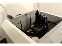
Part 2 of the NeoDue upgrade - a 5" display case that fits onto the Neo (and can be printed on it despite its print size limitations).
You need:
one of each parts
7x 3 mm x 14 mm plastic screws (four for the display, three for assembling the base pieces together)
1x 3 mm x 6 mm plastic screw for the adapter board of the display
4x 3 mm x 8 mm plastic screws for mounting the display onto the base
2x M4 x 20...30 mm screws for mounting the complete display onto the Neo (i used some leftovers from Ikea with a large head). Preferrably you might want cut the thread for these screws ont the Neo metal base, otherwise you will need two M4 nuts to scure the screws.
Additionally you will need a drill for the holes (screws and cable) in the printer itself.
Prio to assembly:
try to assemble the parts, slightly sand the connecting geometries if needed.
surface finish all parts as you like
remove adapter board from touchscreen
Assembly:
assemble display frame and display by using the two connector rods and the four 14mm screws. Take care you place the connector rods correctly.
place base parts onto Neo printer and check if they fit correctly. The connection surfaces are partially cut out so that they can easily be sanded down one mm were needed to accomodate for manufacturing tolerances of the frame. Both pieces should fit snugly over their whole contact surface (visible from the sides).
assemble both base parts by screwing them together with the remaining 14mm screws. Carefully align them in this process.
check the correct seating on the Neo frame once more, slide the base to the left until it touches the left wall of the Neo case.
with the base seated, mark the holes for the M4 screws and the holes for the wire. The hole for the wire facing the display should be rather on the right side of the cable channel to enable the sliding movement needed for seating.
drill the holes, cut the M4 thread, very carefully remove any burrs and sharp edges from the cable holes.
assemble base part and display and secure with the four 8mm screws
guide cable through holes in Neo base, slide display into place and secure with M4 screws.
plug cable into your Duet electronics and enjoy your upgraded 3D printer with Wifi and display :-)
The hole nearby the "E" of the Neo logo in the display frame can be used to push the "Erase" button of the display. The hole inside the Duet Logo can be used to reset the display if needed. The USB port for updating the display firmware is accessible from the side.
Similar models
thingiverse
free

Picture Frame Case for 5" Raspberry Pi Display (Joy-IT RB-LCD-5) by CaptSL
...it fits into a albrunna frame from ikea or similar you need to cut away the holes for the...
thingiverse
free

X carriage mounted extruder filament guide by jwass
...to the bearing mount to go from your spool to the guide to keep your filament from touching your work surface an picking up dirt.
thingiverse
free

Hole Grommet for Cable Passage in Desk or Enclosure by psdesign
...th a 64mm hole saw. insert hard plastic base, then insert the rubber part, pass cables.
if you make one please post your photos!
thingiverse
free

Z-limit endstop switch support for FLSUN Cube by tato_713
...u need to screw the endstop with the original m2.5 sets, this part is attached by force in one side carry bar.
version 5 assembly
thingiverse
free

Lerdge Display Panel Mount with USB Connector by darwin-de
...ed frames with m3 screws from the rear side,
they fit directly into the correspondending holes,
no threaded inserts are required.
thingiverse
free

Cable chain brackets for Tevo Tarantula bed by alejandrosnz
...a printer.
you will need to glue the bed part, hot glue will be enough. for the frame bracket you will need a m4 screw and t-nut.
thingiverse
free

CYBERPUNK AR DISPLAY STAND (Airsoft ONLY) by gumo_design
...e recommended.
you can adjust the balancing by sliding the part a.
there's a 0.36 hole in the bottom for a m4 stopping screw.
thingiverse
free

Hero Me Fan Duct for Ender 3 (2019) Full OEM. No other parts needed
...an to secure part cooler duct on base.
insert original part cooler and secure with the two longer part cooler fan screws to duct.
thingiverse
free

NeoDue Part 1 - Duet Wifi for GRR Neo by Mechanotronikum
..., just add a bat43 diode as mentioned in the duet wiki.)
the steppers work fine on my machine if i let them run with 500...600ma.
thingiverse
free

IKEA SIGNUM replacement part by Cacodaemon
...unting hole distance is nearly the same as the distance from the original holders.
you need four m4 screws and nuts for mounting.
Mechanotronikum
thingiverse
free
Bondtech BMG direct drive extruder for GRR Neo by Mechanotronikum
...dapter.
at least on my printer, this upgrade did wonders to print quality relative to the original bowden design. happy printing!
thingiverse
free
NeoDue Part 1 - Duet Wifi for GRR Neo by Mechanotronikum
..., just add a bat43 diode as mentioned in the duet wiki.)
the steppers work fine on my machine if i let them run with 500...600ma.
Grr
3dfindit
free

GRR
...grr
3dfind.it
catalog: festo
3dfindit
free

GRR
...grr
3dfind.it
catalog: festo
thingiverse
free

GRR-RIPPER Heel
...ush block.
these are disposable parts; print your own replacement!
this variant has a couple of holes for a jig fitting i needed.
thingiverse
free

E3D FAN GRR X400 Bauteilkühler by Kernfusion
...r x400 bauteilkühler by kernfusion
thingiverse
this is a remix of https://www.thingiverse.com/thing:1591912
a little bit shorter
thingiverse
free

GRR NEO Extruder tool by NitroXpress
...ool to de-tension the pressure roll of the german reprap neo filament extruder.
much easier to thread the filament.
have fun...
thingiverse
free

LCD display cover for GRR Protos V3 by kloberujo
...b of the lcd-display of german reprap's protos v3 - it just looks nicer like that. if precisly printed fits without fixtures.
thingiverse
free

Messuhrhalter für der GRR Neo by Helisinus
...ötigt.
english:
dial indicator for grr neo.
you need to extend the dial indicator and you need 6 x neodymium magnets 5mm x 2mm
thingiverse
free
Bondtech BMG direct drive extruder for GRR Neo by Mechanotronikum
...dapter.
at least on my printer, this upgrade did wonders to print quality relative to the original bowden design. happy printing!
thingiverse
free

Microjig GRR-RIPPER Gravity Heel Kit
...1.0.0.4a004c4dcjk0si
all in, parts should be less than $3.00
when fully retracted, the heel is about 1mm above the surface plane.
thingiverse
free
NeoDue Part 1 - Duet Wifi for GRR Neo by Mechanotronikum
..., just add a bat43 diode as mentioned in the duet wiki.)
the steppers work fine on my machine if i let them run with 500...600ma.
Paneldue
thingiverse
free

PanelDue enclosure by dc42
... version 2.0 in customizer.
new! this design now supports the integrated 5" and 7" versions of paneldue in customizer.
thingiverse
free

PanelDue 5" Back Cover for RailcoreII by kraegar
... railcoreii
does not fit the paneldue 5i
use with dc42's 5" paneldue case here: https://www.thingiverse.com/thing:656884
thingiverse
free

PanelDue 7i by kamikazer2
...paneldue 7i by kamikazer2
thingiverse
you need 4 m3x30 + nuts and 1 m3x6
thingiverse
free

Prusa PanelDue mount
... mount was inspired by https://www.thingiverse.com/thing:3286954 mount.
the back panel has a hole to fit the 4 pin cable through.
thingiverse
free

PanelDue 4.3" Compact Enclosure by SlimShader
...losure by slimshader
thingiverse
a compact enclose for the paneldue 4.3" display, frame mountable complete with back plate.
thingiverse
free

Ormerod PanelDue mounting bracket by 3jimd
...acket by 3jimd
thingiverse
this is a bracket and hinge for mounting dc42's paneldue lcd control panel on the reprap ormerod.
thingiverse
free

Sapphire plus duet paneldue mount by Szwalkiewicz
... the factory location
i use the paneldue lcd case form lumberjackengineering to completehttps://www.thingiverse.com/thing:2799628
thingiverse
free

PanelDue 5i encloser by danny_v1
...er for the front, without any holes for the sd card or something else.
it can be mounted with one screw to a 2020 or 3030 frame.
thingiverse
free

Case for PanelDue 4.3 duet3d by drbit
...for paneldue 4.3 duet3d by drbit
thingiverse
compact case for paneldue 4.3 duet3d
need m3 bolts
added support lerdge screen size
thingiverse
free

Bracket for a PanelDue by stephenrc
...ne for the 4.3" and in the scad file there is a version with a tab on one end for mounting above or below a horizontal 2020.
Neo
design_connected
$18

Neos
...neos
designconnected
wilkhahn neos computer generated 3d model. designed by wiege.
design_connected
$7

Neos
...neos
designconnected
gruppo feg neos computer generated 3d model. designed by nunziati, matteo.
turbosquid
$7

NEO
...
royalty free 3d model neo for download as max, obj, and fbx on turbosquid: 3d models for games, architecture, videos. (1219070)
turbosquid
$30

Neo
... available on turbo squid, the world's leading provider of digital 3d models for visualization, films, television, and games.
3ddd
$1
Neo chair
...neo chair
3ddd
кресло
http://www.ufficidea.com/schedaprodotto_2720_seduta-direzionale-neo-chair.php
3ddd
$1
Riho NEO
... угловая
угловая акриловая ванна neo 140л.
фабрика изготовитель - riho
страна производитель: чехия
размер: 140 x 140 см
3ddd
$1
DUNE - NEO
... панель
186536 neo
29x29 cm./ 11,42”x11,42” d935
8 mm. de espesor/thicknesshttp://www.dune.es
3ddd
$1
Neo
...neo
3ddd
3d max 2009,vray 1.5 sp2+fbx
3ddd
$1
Russion neo classic
...russion neo classic
3ddd
lustra russion neo classic
3d_export
$7
neo matrix 1999
...neo matrix 1999
3dexport
neo matrix 1999 под печать
Display
3ddd
$1

Display
...display
3ddd
терминал
display computer 3d model
3d_export
$5
Display
...display
3dexport
display<br>verts 2.262<br>faces 3.928
turbosquid
$8

Display
...turbosquid
royalty free 3d model display for download as fbx on turbosquid: 3d models for games, architecture, videos. (1634534)
3ddd
$1
Display cabinet
...display cabinet
3ddd
витрина
display cabinet
turbosquid
$50

display
... available on turbo squid, the world's leading provider of digital 3d models for visualization, films, television, and games.
turbosquid
$25

DISPLAY
... available on turbo squid, the world's leading provider of digital 3d models for visualization, films, television, and games.
turbosquid
$10
Display
...e 3d model display for download as ma, max, obj, fbx, and dae on turbosquid: 3d models for games, architecture, videos. (1387472)
3d_export
$6
display stand
...display stand
3dexport
super market display stand
3d_ocean
$12
Display Case
...rnishing furniture glass storage vetrinetta white
a 3d model of a display case. the texture for the back of the case is provided.
3d_export
$30

Vehicle display
...vehicle display
3dexport
vehicle display consists of podium and vehicle cover no vehicle there is a veiled vehicle silhouette
5
turbosquid
$6
Rock 5-5
...urbosquid
royalty free 3d model rock 5-5 for download as obj on turbosquid: 3d models for games, architecture, videos. (1639063)
3d_export
$5
hinge 5
...hinge 5
3dexport
hinge 5
turbosquid
$10
A-5
... available on turbo squid, the world's leading provider of digital 3d models for visualization, films, television, and games.
turbosquid
$2
A-5
... available on turbo squid, the world's leading provider of digital 3d models for visualization, films, television, and games.
turbosquid
$12

Calligraphic Digit 5 Number 5
...hic digit 5 number 5 for download as max, obj, fbx, and blend on turbosquid: 3d models for games, architecture, videos. (1389333)
3ddd
$1

5 роз
...5 роз
3ddd
5 роз в стеклянной вазе
design_connected
$11

iPhone 5
...iphone 5
designconnected
apple iphone 5 computer generated 3d model.
3ddd
$1
Lola 5
...lola 5
3ddd
miniforms
lola 5 miniforms 300*65*134
3ddd
$1

Nexus 5
...dd
nexus , phone , телефон
google nexus 5 phone
3d_ocean
$15
iPhone 5
...iphone 5
3docean
3d 4d apple cinema iphone model modeling phone screen texture
iphone 5 3d model and texture realistic iphone 5.
Part
3d_export
$5
Parts
...parts
3dexport
parts
3d_export
$5
Part
...part
3dexport
part
3d_export
$5

Part
...part
3dexport
machine part
3d_export
$65
Part
...part
3dexport
simple rendering of the scene file
3d_export
$65

Part
...part
3dexport
simple rendering of the scene file
3d_export
$30

fan part
...fan part
3dexport
this is a part of fan of pedastal
3d_export
$10
machine parts
...machine parts
3dexport
3d part modeling work ,contact for 3d work
turbosquid
$59

Mechanical Part
...id
royalty free 3d model mechanical part for download as c4d on turbosquid: 3d models for games, architecture, videos. (1410833)
turbosquid
$17
Road parts
...bosquid
royalty free 3d model road parts for download as 3ds on turbosquid: 3d models for games, architecture, videos. (1192967)
turbosquid
$9

Cutter Parts
...squid
royalty free 3d model cutter parts for download as stl on turbosquid: 3d models for games, architecture, videos. (1220010)
2
design_connected
$11
No 2
...no 2
designconnected
sibast no 2 computer generated 3d model. designed by sibast, helge.
turbosquid
$6
Cliff Rock 2-2
...uid
royalty free 3d model cliff rock 2-2 for download as obj on turbosquid: 3d models for games, architecture, videos. (1619161)
turbosquid
$29

Book variation 2 2
...3d model book variation 2 2 for download as max, obj, and fbx on turbosquid: 3d models for games, architecture, videos. (1366868)
turbosquid
$22
Classic baluster (2) (2)
...assic baluster (2) (2) for download as max, obj, fbx, and stl on turbosquid: 3d models for games, architecture, videos. (1483789)
turbosquid
$99

Smilodon 2 Pose 2
... available on turbo squid, the world's leading provider of digital 3d models for visualization, films, television, and games.
turbosquid
$20

Barrel Barricade 2-2
... available on turbo squid, the world's leading provider of digital 3d models for visualization, films, television, and games.
turbosquid
$6
Wall Trophy (2) (2)
... available on turbo squid, the world's leading provider of digital 3d models for visualization, films, television, and games.
turbosquid
free
Tire label 2 of 2
... available on turbo squid, the world's leading provider of digital 3d models for visualization, films, television, and games.
3ddd
$1

Кровать, 2 тумбочки, 2 светильника
...кровать, 2 тумбочки, 2 светильника
3ddd
кровать, 2 тумбочки, 2 светильника
нормальное качество
формат 3ds max
без текстур
3ddd
free

Кровать, 2 тумбочки, 2 светильника
...кровать, 2 тумбочки, 2 светильника
3ddd
кровать, 2 тумбочки, 2 светильника
нормальное качество
формат 3ds max
без текстур