Thingiverse

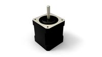
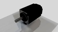
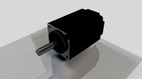
NEMA 17 10:1 Cycloidal Drive by EngineeringFruit
by Thingiverse
Last crawled date: 3 years, 3 months ago
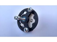
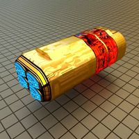
A functional 3D printed 10:1 cycloidal drive for the NEMA 17 stepper motor. Customizable by swapping out a couple components (rotor, input shaft, middle ring) allowing for quick reduction modifications even if the parts aren't pre-printed. The larger components (base, output shaft, top) can be reused with different reductions. This design requires minimal, common hardware you may have on hand as listed below:
4x Housing Bolts 1/4" x 3/4" (Holes can be modified or drilled out to fit M7)
4x Housing Bolt Nuts 1/4"
4x Base Screws M3 x 6mm
28x BBs 6mm (Optional works well without)
1x Bearing 6mm ID x 15mm OD x 5mm Width
The relatively large package size is a consequence from using 3D printed shafts that experience high stress but another advantage is the printer's tolerance can be relatively large. The most frequent failure point is the input shaft. Through testing the rpm output is 10 times lower than input and the torque capacity is 3 times greater than a standard NEMA 17.
The model was created in Fusion 360 using a script written by mawildoer that can be found here: https://github.com/mawildoer/cycloidal_generator When the model was designed Fusion 360 did not have the capability to sketch an equation driven curve through its GUI but does have the ability through the API and mawildoer did just that.
A technical discussion and equations describing how to generate the rotor design can be found here: https://doi.org/10.1515/ama-2016-0022
The Fusion 360 files can be downloaded for use from the following link:https://a360.co/3cicRs2
Assembly
Press the bearing onto the input shaft
Slide the input shaft onto the NEMA 17 motor shaft making sure to align the D shaft profile.
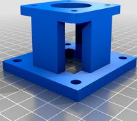
Attach the NEMA 17 to the base using the M3 machine screws
Check if the shaft and bearing are positioned correctly by visually making sure the bearing sticks out of the base and the bearings is relatively flush to the outer surface of the base
Press the rotor onto the bearing till it meets the outer surface of the base
Place the middle ring around the rotor and turn the middle ring till the bolt holes line up on the outside perimeter
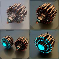
Place the output shaft, pins down, onto a level table and fill the BB tracks with 6mm BBs
Place the top cover over the output shaft carefully to not knock out the BBs and once against the BBs press down to lock the BBs in the top cover. The two parts should not be easily separable
Place the top cover assembly over the rotor aligning output shaft pins with the holes in the rotor and twist the top cover to align the perimeter bolt holes
Fasten the housing together using 1/4" bolts and nuts
Printing Notes
Printing in Low resolution increases layer height which increases the overall part strength.
Pictured is orange ABS and gray PLA due to limited ABS supply
Unless mentioned layer height of 0.3mm
Base: Perimeter: 3 Infill: 0.2 and use support
Orient circular side down
Input Shaft: Perimeter: 4 Infill: 0.2 Layer height 0.1mm and use support
Orient input shaft axis parallel to build plate plane to increase strength
Rotor: Perimeter: 3 Infill: 0.2
Orient flat
Ring: Perimeter: 3 Infill: 0.2
Orient flat
Output shaft: Perimeter: 4 Infill: 0.2 and use support
Orient output shaft axis parallel to build plate plane to increase strength
Top: Perimeter: 2 Infill: 0.2 and use support
Orient larger circular side down
4x Housing Bolts 1/4" x 3/4" (Holes can be modified or drilled out to fit M7)
4x Housing Bolt Nuts 1/4"
4x Base Screws M3 x 6mm
28x BBs 6mm (Optional works well without)
1x Bearing 6mm ID x 15mm OD x 5mm Width
The relatively large package size is a consequence from using 3D printed shafts that experience high stress but another advantage is the printer's tolerance can be relatively large. The most frequent failure point is the input shaft. Through testing the rpm output is 10 times lower than input and the torque capacity is 3 times greater than a standard NEMA 17.
The model was created in Fusion 360 using a script written by mawildoer that can be found here: https://github.com/mawildoer/cycloidal_generator When the model was designed Fusion 360 did not have the capability to sketch an equation driven curve through its GUI but does have the ability through the API and mawildoer did just that.
A technical discussion and equations describing how to generate the rotor design can be found here: https://doi.org/10.1515/ama-2016-0022
The Fusion 360 files can be downloaded for use from the following link:https://a360.co/3cicRs2
Assembly
Press the bearing onto the input shaft
Slide the input shaft onto the NEMA 17 motor shaft making sure to align the D shaft profile.
Attach the NEMA 17 to the base using the M3 machine screws
Check if the shaft and bearing are positioned correctly by visually making sure the bearing sticks out of the base and the bearings is relatively flush to the outer surface of the base
Press the rotor onto the bearing till it meets the outer surface of the base
Place the middle ring around the rotor and turn the middle ring till the bolt holes line up on the outside perimeter
Place the output shaft, pins down, onto a level table and fill the BB tracks with 6mm BBs
Place the top cover over the output shaft carefully to not knock out the BBs and once against the BBs press down to lock the BBs in the top cover. The two parts should not be easily separable
Place the top cover assembly over the rotor aligning output shaft pins with the holes in the rotor and twist the top cover to align the perimeter bolt holes
Fasten the housing together using 1/4" bolts and nuts
Printing Notes
Printing in Low resolution increases layer height which increases the overall part strength.
Pictured is orange ABS and gray PLA due to limited ABS supply
Unless mentioned layer height of 0.3mm
Base: Perimeter: 3 Infill: 0.2 and use support
Orient circular side down
Input Shaft: Perimeter: 4 Infill: 0.2 Layer height 0.1mm and use support
Orient input shaft axis parallel to build plate plane to increase strength
Rotor: Perimeter: 3 Infill: 0.2
Orient flat
Ring: Perimeter: 3 Infill: 0.2
Orient flat
Output shaft: Perimeter: 4 Infill: 0.2 and use support
Orient output shaft axis parallel to build plate plane to increase strength
Top: Perimeter: 2 Infill: 0.2 and use support
Orient larger circular side down
Similar models
grabcad
free

Cycloidal drive
...ycloidal disc rotates. the radial motion of the disc is not translated to the output shaft.
***giff source:stephen kingston***
thingiverse
free

Nema 17 Cycloidal Gear box prototype by chriswal
...ltiple output shaft options
cleanup openscad files for publishing
as i have no time at the moment i post the messy openscad files
thingiverse
free

Coupler Nema 17 - 6 - 6.32 - 8 mm by o3blig
...ozle: 0,4mm
extrusion width: 0,45mm
layer height: 0,2mm
top layers: 4
buttom layer: 4
outline perimeter: 2
infill: fast honey 30%
thingiverse
free

NEMA 17 Motor cover with connector by GarageMZ
...or by garagemz
thingiverse
this is nema 17 steper motor back cover with connector slot.
material is pla, print at 0.2 infill 50%
grabcad
free

Bearing
...r shafts.
reduces friction at the transmission point of motion of the shaft..
reduces work input and increases work output..
thingiverse
free

Nema 17 2020 Extrusion Bracket by Terminator15
...
thingiverse
nema 17 bracket to mount onto 2020 extrusion. print with 2-3 perimeters and 50% infill.
.2mm layers is fine
enjoy!!
grabcad
free

Cyclodial Drive
...in turn drives the cycloidal disc in an eccentric, cycloidal motion.
cad platform: solidworks 2014
render platform: keyshot 4.09
grabcad
free

Nema 17 motor
...nema 17 motor
grabcad
nema 17 bldc motor.
5mm output shaft
thingiverse
free

Nema 17 Block - 6mm, 1/4" - 20mm by spingoogL
...www.thingiverse.com/thing:1789405.
i've trimmed the height of the block to allow more clearance for the standard motor shaft.
thingiverse
free

Alumunium profile 3030 Carriage slider by squadzone
...h
4 bolts 8mm length 70mm
2 bolts 8mm length 45mm
2 bolts 6mm length 40mm
2 bolts 6mm length 55mm
6 lock nuts 8mm
4 lock nuts 6mm
Cycloidal
3d_export
$10

cycloidal drive
...cycloidal drive
3dexport
cycloidal drive
thingiverse
free
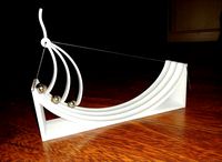
Cycloid art by papp328
...cloid art by papp328
thingiverse
an artistic physic experiment. the curve is a cycloid which has famous features. look after it.
thingiverse
free

Half Cycloid Spiral Spacecurve by espen
...half cycloid spiral spacecurve by espen
thingiverse
half cycloid spiral spacecurve.
thingiverse
free
cycloid gear script by ekaggrat
...based on a alternating epicycloid and hypocycloid tooth profile,... http://demonstrations.wolfram.com/cycloidalears/ ...
thingiverse
free

Cycloidal Knot by mm1440
...cycloidal knot by mm1440
thingiverse
square tube rotating around space curve.
thingiverse
free
Cycloid Period Experiment Cit with Arduino by CNSHmath
...cycloid period experiment cit with arduino by cnshmath
thingiverse
cycloid model to sound its period using arduino
thingiverse
free

Cycloidic Vase (t-glase) by scottvader
...hingiverse
a simple vase created using solidworks lofts to connect two cycloidic gear like ends. looks great in taulman t-glase.
thingiverse
free

Cycloid Penny Slide by guido666
...e curve problem, which is the curve of fastest descent due to gravity. you can store some pennies in the slots in the base, too.
thingiverse
free
Cycloidal Drive by Meia
...m5 bolt, 1 m3 bolt and a small 5mm washer.
if you put it together carefully and maybe sand it a little it will run very smoothly.
thingiverse
free
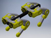
Quadruped with 3D cycloidal Gearboxes
...th modified shaft)
absolute magnetic encoder as5147 (custom board)
https://hackaday.io/project/167855-simple-cycloidal-robot-knee
Nema
3d_export
$5
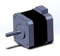
Electric Motor Nema 17
...electric motor nema 17
3dexport
40mm stepper motor nema 17 1.5a (17hs4401) motor 4-wire for 3d printer
turbosquid
$3
Nema 17
...rbosquid
royalty free 3d model nitro engine for download as on turbosquid: 3d models for games, architecture, videos. (1449252)
turbosquid
$1
Nema 17 Stepper motor
... available on turbo squid, the world's leading provider of digital 3d models for visualization, films, television, and games.
turbosquid
$1
Nema 17 Stepper Motor 59Nm
... available on turbo squid, the world's leading provider of digital 3d models for visualization, films, television, and games.
turbosquid
$3
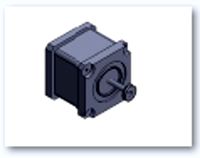
Simple model of Nema 8 stepper motor
...del of nema 8 stepper motor for download as ipt, obj, and stl on turbosquid: 3d models for games, architecture, videos. (1543132)
3d_export
$5

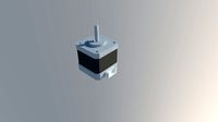
simple model of nema 17 stepper motor
...ort
simple model, useful to prototype robots, 3d printers and other electronic diy projects<br>step and .ipt file included
3d_export
$5
simple model of nema 8 stepper motor
...robots, 3d printers and other electronic diy projects<br>current model: 20bygh33-0604a<br>step and .ipt file included
3ddd
free

Larte Luce
...class="star five "></div></div></li><li><img src="http://b.3ddd.ru/media/cache/sky_user_avatar_comment/avatar/users/117489.jpg" alt="ci-nema" width="35" height="35" class="img"><div class="name"><a href="/users/ci-nemaquot;>ci-nema</a></div><div class="raiting"><div class="star five "></div></div></li></ul><div class="more"><a href="/3dmodels/show/larte_luce/voted">еще</a></div></div><div class="number" rating="30" count="6"...
thingiverse
free

Nema 14 to Nema 17 Adapter by lukepat
...nema 14 to nema 17 adapter by lukepat
thingiverse
created a adapter for nema 14 to nema 17 mount.
thingiverse
free
Distance Nema 17 and Nema 23 by Krzysztof_Handtke
...distance nema 17 and nema 23 by krzysztof_handtke
thingiverse
distance to nema motors to build a cnc milling machine.
17
3d_export
$6
rocks 17
...rocks 17
3dexport
rocks 3d model 17
3ddd
$1

PLANTS 17
...plants 17
3ddd
цветок , горшок
plants 17,, pots in diameter 100,80,60,40cm,,, enjoy
3d_export
$6
tap-17
...tap-17
3dexport
3d_export
$6
set-17
...set-17
3dexport
3d_export
$27

C-17 Globemaster
...c-17 globemaster
3dexport
c-17 globemaster
3ddd
free

Renault FT-17
...renault ft-17
3ddd
ft-17 , renault , танк
turbosquid
$40
cottage 17
...bosquid
royalty free 3d model cottage 17 for download as max on turbosquid: 3d models for games, architecture, videos. (1377003)
turbosquid
$30

Apartment 17
...squid
royalty free 3d model apartment 17 for download as max on turbosquid: 3d models for games, architecture, videos. (1432680)
turbosquid
$10

Surfboard 17
...squid
royalty free 3d model surfboard 17 for download as max on turbosquid: 3d models for games, architecture, videos. (1375686)
turbosquid
$7
Rock 17
...turbosquid
royalty free 3d model rock 17 for download as obj on turbosquid: 3d models for games, architecture, videos. (1486522)
Drive
turbosquid
$90
Drive
...turbosquid
royalty free 3d model drive for download as blend on turbosquid: 3d models for games, architecture, videos. (1654393)
3d_export
$10
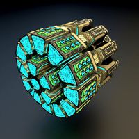
cycloidal drive
...cycloidal drive
3dexport
cycloidal drive
3d_ocean
$5
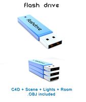
Flash Drive
...h drive included : – materials – scene ( lighs / room ) – .c4d + .obj for any questions please feel free to contact me thank you.
3d_ocean
$5

Usb drive
...s shaders and a lighting setup. it also has a small animation of it going in and out. i saved it out as both a .blend file and...
3d_ocean
$5

Pen Drive
...est computer drive game model good low poly new pen pen drive textured unwrapped uv very low poly
a very beautiful low poly model
3d_ocean
$10
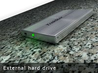
External hard drive
... is a detailed model of a trekstor external hard drive. you can easily modify the label on the top. simply edit the text objects.
turbosquid
$60

Star Drive
...squid
royalty free 3d model star drive for download as blend on turbosquid: 3d models for games, architecture, videos. (1254314)
turbosquid
$50

Star Drive
...squid
royalty free 3d model star drive for download as blend on turbosquid: 3d models for games, architecture, videos. (1263524)
turbosquid
$45
Star Drive
...squid
royalty free 3d model star drive for download as blend on turbosquid: 3d models for games, architecture, videos. (1287060)
turbosquid
$40
Star Drive
...squid
royalty free 3d model star drive for download as blend on turbosquid: 3d models for games, architecture, videos. (1261902)
10
turbosquid
$25

10
... available on turbo squid, the world's leading provider of digital 3d models for visualization, films, television, and games.
turbosquid
$10
a-10
... available on turbo squid, the world's leading provider of digital 3d models for visualization, films, television, and games.
3ddd
$1

EX 10
...ex 10
3ddd
samsung , фотоаппарат
ex 10
3ddd
$1

Bed 10
...bed 10
3ddd
постельное белье
bed 10
evermotion
$25
Scene 10 Archinteriors vol. 10
...dering design interior
take a look at textured and shadered visualization scene ready to be rendered.. evermotion 3d models shop.
3ddd
$1

Curtains 10
...curtains 10
3ddd
curtains 10
3ds max 2011,fbx + textures
polys: 100355
3ddd
free

PLANTS 10
...plants 10
3ddd
цветок , горшок
plants 10,, with 3 different color planter boxes
turbosquid
$24

Chandelier MD 89310-10+10 Osgona
... chandelier md 89310-10+10 osgona for download as max and fbx on turbosquid: 3d models for games, architecture, videos. (1218762)
design_connected
$29
Nuvola 10
...nuvola 10
designconnected
gervasoni nuvola 10 computer generated 3d model. designed by navone, paola.
design_connected
$22

Kilt 10
...kilt 10
designconnected
zanotta kilt 10 computer generated 3d model. designed by progetti, emaf.
1
turbosquid
$69

armchairs(1)(1)
... available on turbo squid, the world's leading provider of digital 3d models for visualization, films, television, and games.
turbosquid
$15
ring 1+1
... available on turbo squid, the world's leading provider of digital 3d models for visualization, films, television, and games.
turbosquid
$10
chair(1)(1)
... available on turbo squid, the world's leading provider of digital 3d models for visualization, films, television, and games.
turbosquid
$8

Chair(1)(1)
... available on turbo squid, the world's leading provider of digital 3d models for visualization, films, television, and games.
turbosquid
$2

RING 1(1)
... available on turbo squid, the world's leading provider of digital 3d models for visualization, films, television, and games.
turbosquid
$1
house 1(1)
... available on turbo squid, the world's leading provider of digital 3d models for visualization, films, television, and games.
turbosquid
$1

Table 1(1)
... available on turbo squid, the world's leading provider of digital 3d models for visualization, films, television, and games.
turbosquid
$59

Formula 1(1)
...lty free 3d model formula 1 for download as max, fbx, and obj on turbosquid: 3d models for games, architecture, videos. (1567088)
design_connected
$11
No 1
...no 1
designconnected
sibast no 1 computer generated 3d model. designed by sibast, helge.
turbosquid
$2
desert house(1)(1)
...3d model desert house(1)(1) for download as 3ds, max, and obj on turbosquid: 3d models for games, architecture, videos. (1055095)