GrabCAD

NASA No-Fuss Fuselage
by GrabCAD
Last crawled date: 1 year, 10 months ago
This is my entry for the NASA challenge found here:
https://grabcad.com/challenges/nasa-challenge-new-transonic-wind-tunnel-test-section
Modeled using SolidWorks and Visuals done with Unreal Engine 5
STEP Files Included
GIF Animations Included
Video Link Animation Included
https://youtu.be/yhocq5uioDk
Extra Renderings Included
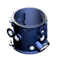
I had a lot of ideas for this challenge, but “lightning” didn’t strike until about 10 days ago while I was researching how to repair a ball valve (like the ball valve used in plumbing). Although I learned a lot about repairing valves in the Navy, I had to review the basics and found that the basics was all I needed to draw inspiration from for this NASA challenge.
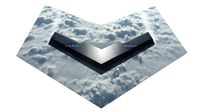
My entry in essence, is a giant ball valve. The obvious main difference is the fuselage test section that slips into and out of the crane-facing side of the wind tunnel loop. When in operation, it offers a leak-proof boundary from the wind tunnel loop circuit, and the separated slip fuselage allows for a model to be set up and preconfigured ahead of test time. Installed are several cameras and interior lights for capturing video and photogrammetry of the test model, and the configurable mounts exist where the sight glass hatch parts are currently installed on the fuselage body.
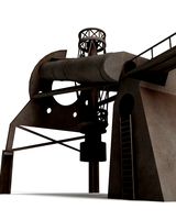
I’ve run out of time visually implementing all of my additional thoughts and ideas to contribute to this challenge, but I would imagine Building 1 conducts the tests and is home to the testing loop and testing chamber. The testing fuselage is shuttled to-and-from Building 2 which is the workshop and hangar bay to all the fuselage test sections.
Thanks for checking out the video animation and the project files!
Special thanks to NASA for sponsoring another amazing challenge here on GrabCAD!
https://grabcad.com/challenges/nasa-challenge-new-transonic-wind-tunnel-test-section
Modeled using SolidWorks and Visuals done with Unreal Engine 5
STEP Files Included
GIF Animations Included
Video Link Animation Included
https://youtu.be/yhocq5uioDk
Extra Renderings Included
I had a lot of ideas for this challenge, but “lightning” didn’t strike until about 10 days ago while I was researching how to repair a ball valve (like the ball valve used in plumbing). Although I learned a lot about repairing valves in the Navy, I had to review the basics and found that the basics was all I needed to draw inspiration from for this NASA challenge.
My entry in essence, is a giant ball valve. The obvious main difference is the fuselage test section that slips into and out of the crane-facing side of the wind tunnel loop. When in operation, it offers a leak-proof boundary from the wind tunnel loop circuit, and the separated slip fuselage allows for a model to be set up and preconfigured ahead of test time. Installed are several cameras and interior lights for capturing video and photogrammetry of the test model, and the configurable mounts exist where the sight glass hatch parts are currently installed on the fuselage body.
I’ve run out of time visually implementing all of my additional thoughts and ideas to contribute to this challenge, but I would imagine Building 1 conducts the tests and is home to the testing loop and testing chamber. The testing fuselage is shuttled to-and-from Building 2 which is the workshop and hangar bay to all the fuselage test sections.
Thanks for checking out the video animation and the project files!
Special thanks to NASA for sponsoring another amazing challenge here on GrabCAD!
Similar models
grabcad
free
![[Design Concept] New Transonic Wind Tunnel Test Section | NASA 2022](/t/12053983.jpg)
[Design Concept] New Transonic Wind Tunnel Test Section | NASA 2022
...test section
additional files to follow :
- complete design
- installing mechanism and animation
- wind tunnel simulation result
grabcad
free
![[Mechanical Design] New Transonic Wind Tunnel Test Section | NASA 2022](/t/12050280.jpg)
[Mechanical Design] New Transonic Wind Tunnel Test Section | NASA 2022
...tion
additional files on progress :
- complete design soon
- installing mechanism and animation
- wind tunnel simulation result
grabcad
free

NASA Challenge: New Transonic Wind Tunnel Test Section
...nasa challenge: new transonic wind tunnel test section
grabcad
nasa challenge: new transonic wind tunnel test section
grabcad
free

Interchangeable wind tunnel test section
...interchangeable wind tunnel test section
grabcad
nasa challenge of transonic wind tunnel test section
grabcad
free

NASA Wind Tunnel Facility
...this design is the choice and improves operational and human factors in the wind tunnel facility and supports wind tunnel tests .
grabcad
free

Just some renderings of the NASA Challenge: New Transonic Wind Tunnel Test Section
...d tunnel test section
grabcad
https://grabcad.com/challenges/nasa-challenge-new-transonic-wind-tunnel-test-section
rendus plans
grabcad
free

Transonic Wind Tunnel Test Section
... magazine i think it's simple and cool. maybe the construction will be a bit expensive but i think nasa will like this design
grabcad
free

Prototype Nasa
...prototype nasa
grabcad
nasa challenge: new transonic wind tunnel test section
grabcad
free

NASA Challenge: New Transonic Wind Tunnel Test Section
...nasa challenge: new transonic wind tunnel test section
grabcad
https://www.linkedin.com/in/andrepereirabarros
grabcad
free

Nasa Challenge : Wind Tunnel Test Section
...lenge. the exact required dimensions are implemented here. a crane is also designed to put the rockets or planes into the tunnel.
Fuss
cg_studio
$149

SD.KFZ 251/1 Ausf.C - Stuka zu Fuss3d model
...s .c4d .lwo .obj - sd.kfz 251/1 ausf.c - stuka zu fuss 3d model, royalty free license available, instant download after purchase.
3d_ocean
$5

Great Global illumination setup
...global illumination setup. if you don’t like all the fuss using the shadows from the lights then this is...
3d_export
$10

Set
...3dexport boyd is sharp, modern and architecturally intriguing. no fuss required because the impression has already been made.<br>designed and...
3d_export
$5

audra umbrella stand
...audra umbrella stand 3dexport simple, clean-lineds, and no fuss the audra umbrella stand has two separate compartments for...
3d_export
$9

industrial - military - vehicular debris pack of 50 plus
.../ dystopian sceneries and views more organic with little fuss ...
thingiverse
free

Fuss 70x70 Profiel by josi1992
...fuss 70x70 profiel by josi1992
thingiverse
fuss 70x70 profiel
thingiverse
free

Flying Bear P902 Fuss by Dampfbier
...flying bear p902 fuss by dampfbier
thingiverse
flying bear p902 fuss
thingiverse
free

Handyhalterung mit beweglichem Fuss by Ne0th0r
...handyhalterung mit beweglichem fuss by ne0th0r
thingiverse
handyhalterung mit beweglichem fuss. erstellt mit fusion 360.
thingiverse
free

IKEA Fuss ALEX Schubladenelement 119363
...ikea fuss alex schubladenelement 119363
thingiverse
ikea fuss alex schubladenelement 119363
ikea foot alex drawer element 119363
thingiverse
free

Fuss Papa by nghrr
...fuss papa by nghrr
thingiverse
this thing was made with tinkercad. edit it online https://tinkercad.com/things/jufsztcfbqf
Fuselage
turbosquid
$60

Airplane fuselage compass
...d model airplane fuselage compass for download as max and obj on turbosquid: 3d models for games, architecture, videos. (1558309)
3d_ocean
$45

Boeing 737-300w
...blender internal render and compositor nodes in blender.for the fuselage doors, wings, tail and...
3d_export
$60

saab j21
...by saab. it used a relatively unorthodox twin boom fuselage with a pusher engine, giving the aircraft an unusual...
3d_ocean
$35

Aviocopter concept aircraft
...internal render. model consists of: front wings, rear tale, fuselage cockpit and propellers with engines. parts are...
cg_studio
$79

Gotha G.V.3d model
...gotha model 3d gv gun military bomber allowed perspectx fuselage versions misile bomb german heavy ww1 .3ds .c4d .fbx...
3d_export
$59

junkers ju-52
...objeckts in a file are divided on layers (a fuselage wings, an interior, gear, etc.) animation: door, cargo doors....
3d_ocean
$19

Embraer 190 commercial jet
...by material and by object.there is one texture for fuselage with windows and...
3d_ocean
$19

Bombardier cs300 airliner
...from the fuselage.there are 3 png textures one for fuselage 2050×2050px with passenger windows...
3d_ocean
$19

Dassault falcon 5x business jet
...render.there are 2 png textures for this model.one for fuselage 2050×2050png pixels...
3d_ocean
$19

Airbus A350-900 commercial aircraft
...standard lighs and materials.there are 2 textures, one for fuselage with windows and tail decals,second is...
Nasa
turbosquid
$49
Nasa Marscopter
...id
royalty free 3d model nasa marscopter for download as max on turbosquid: 3d models for games, architecture, videos. (1323349)
turbosquid
$500
NASA Crawler
... available on turbo squid, the world's leading provider of digital 3d models for visualization, films, television, and games.
turbosquid
$5
Nasa Rocket
... available on turbo squid, the world's leading provider of digital 3d models for visualization, films, television, and games.
turbosquid
$1
NASA Spool.max
... available on turbo squid, the world's leading provider of digital 3d models for visualization, films, television, and games.
3d_export
$15

US NASA 3D Model
...us nasa 3d model
3dexport
spaceship ship nasa battle blender
us nasa 3d model antonielfelain 96625 3dexport
turbosquid
$99
NASA MIT Wing
...oyalty free 3d model nasa mit wing for download as ma and max on turbosquid: 3d models for games, architecture, videos. (1510099)
turbosquid
$29
NASA Electronic Telescope
... available on turbo squid, the world's leading provider of digital 3d models for visualization, films, television, and games.
turbosquid
$6

Real flag NASA
... available on turbo squid, the world's leading provider of digital 3d models for visualization, films, television, and games.
3d_export
$41
NASA FAST Satellite 3D Model
...odel
3dexport
nasa space satellite earth aurora sensor panel solar orbit
nasa fast satellite 3d model visualmotion 20244 3dexport
3d_export
$20

22k photorealistic earth - nasa
...tures directly from nasa.<br>nasa solar system bundle coming soon!<br>contact info@teichmanmedia.eu for all iquiries.