GrabCAD
NASA Lunar Collector
by GrabCAD
Last crawled date: 1 year, 10 months ago
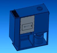
NASA Lunar Sampling System
Prerequisites:
• The collector is mounted on lander or rover handling arm. The interface is adapted to the arm (here as a flange)
• A parallel arm system should be inserted so that the collector can keep contact to the surface. For weight reasons, this is not included in the weight indication
• The collector may be mounted on a vertical axis swing arm so that it can be driven around and thereby cover a circular area
• To minimize the weight, switch between the different containers (here 5) and the chute location, the handling arm is used to push the container row and chute (see below). However, it would be quite easy to add motors or actuators to handle these movements.
• An operator is monitoring the flow by camera and is operating the arm/collector remotely
Comment added 30/9-2018:
3D-printed the hole assembly in half scale 28/9 to test the function, see note below.
- added a STL-file of a stronger screw-helix (Screw -helix thick.STL) 30/9, as the down scaled model was to weak.
Video link added 2/10-2018
Contents:
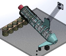
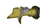
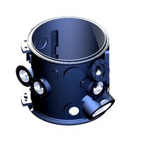
• A slanted Screw/helical (20 degree) with progressive pitch and conical end. The outer edges of the screw are fitted with a soft edge made of Teflon, to achieve a certain scraper effect.
• A Screw Pipe Housing designed so open that it is possible to follow the movements of the rocks through the screw. The inlet will restrict how big the rocks can be. The front opening will allow 20x20mm and the back opening will allow 10mm high rocks, so depending of which direction, the sampler is moved over the surface, two different restriction are active. Bigger rocks are guided away from the opening holes.
• A Sorting Grate located at the end of the screw tube as part of this. The longitudinal ribs of the grate have a growing distance, so that small stones will fall through the grate in its narrow end, while larger stones will be led further up before they fall through the grate. Very small rocks and sand is collected by pushing the chute towards the inlet.
• An open Chute-tube that can be moved in the longitudinal direction of the grate so that the chute opening can be placed under the desired grate opening, and so that stone sizes up to the grate size can pass into the container.
• A Container Magazine, where a number of containers (here 5 pcs.) can be placed in. The magazine is placed underneath the chute's opening and can be slided so that each container can be placed underneath the chute.
• 5 Containers with a stop edge at the top, mounted in the magazine.
• A motor / drive system for rotating the screw fastened to the end of the screw housing. If possible blockage or need for emptying the screw, this can be rotated backwards. Possibly it can be driven
intermittent to avoid blocking.
• A parallel arm system could be mounted between the handling arm and the collector, which ensures that the collector inlet always has contact with the ground in the right orientation. In this way, the operator can concentrate on bringing the collector's inlet across the terrain to hunt stones .
Description:
• The collector is clamped / clicked on the rover or landers handling arm.
• The collector has been made as open as possible so that the entire process can be monitored from the camera.
• The operator guides the arm / Collector opening over the surface where rock is to be collected.
• The Screw rotates and pulls the stones and ralts that have been able to pass through the restrictive opening in the inlet opening.
• When the rocks approach the upper end of the Screw Housing, they pass over a Sorting Grate.
• Depending on where the Chute is located under the Grate, the stones of the correct size will fall into the Container. The Chute is moved according to the wanted size of the rocks, which can be observed through the camera.
• If large items are desired, the Chute is slided away from the inlet and if small rocks are desired, the Chute is pushed against the inlet.
• The setting of the Chute and Container takes place with the lander's arm as the opening in the he end of the Magazine plate is maneuvered over a fixed anchor pole. When moving the arm, the fixed Magazine will be moved relative to the Chute and the relative to the Screw Housing. Once the desired setting is reached, the entire Collector is released from the anchor and thereby ready to continue the stone collection with the new settings.
Options / capabilities:
• Can work on fairly uneven surfaces, as the inlet opening has a rather small touch point. Works best on flat or wavy surfaces.
• Growing cross section -> Less chance of clamping
• Easy to remove the filled container magazine
• Only very little power consumption (only one motor)
• Simple construction -> less problems (KIS)
Data:
• Most of the construction is made of aluminum
• Total weight (excluding motor): less than 1000 grams
• The Collector is printed 3D (in Nylon Onyx, scale 1:2, 0.125mm layer), on a Markforged X7 (results show in the pictures) and therefore the walls are made thicker than necessary than if it was made of aluminum. It seems to function ok, but the print was just finished this afternoon, so I have not testet it yet.
• The uploaded STL-files are 1:1
I have also added a few pictures of my first attempt, which was very compact and light (less than 500 grams :-) I suppose that it will function quite well also.
Prerequisites:
• The collector is mounted on lander or rover handling arm. The interface is adapted to the arm (here as a flange)
• A parallel arm system should be inserted so that the collector can keep contact to the surface. For weight reasons, this is not included in the weight indication
• The collector may be mounted on a vertical axis swing arm so that it can be driven around and thereby cover a circular area
• To minimize the weight, switch between the different containers (here 5) and the chute location, the handling arm is used to push the container row and chute (see below). However, it would be quite easy to add motors or actuators to handle these movements.
• An operator is monitoring the flow by camera and is operating the arm/collector remotely
Comment added 30/9-2018:
3D-printed the hole assembly in half scale 28/9 to test the function, see note below.
- added a STL-file of a stronger screw-helix (Screw -helix thick.STL) 30/9, as the down scaled model was to weak.
Video link added 2/10-2018
Contents:
• A slanted Screw/helical (20 degree) with progressive pitch and conical end. The outer edges of the screw are fitted with a soft edge made of Teflon, to achieve a certain scraper effect.
• A Screw Pipe Housing designed so open that it is possible to follow the movements of the rocks through the screw. The inlet will restrict how big the rocks can be. The front opening will allow 20x20mm and the back opening will allow 10mm high rocks, so depending of which direction, the sampler is moved over the surface, two different restriction are active. Bigger rocks are guided away from the opening holes.
• A Sorting Grate located at the end of the screw tube as part of this. The longitudinal ribs of the grate have a growing distance, so that small stones will fall through the grate in its narrow end, while larger stones will be led further up before they fall through the grate. Very small rocks and sand is collected by pushing the chute towards the inlet.
• An open Chute-tube that can be moved in the longitudinal direction of the grate so that the chute opening can be placed under the desired grate opening, and so that stone sizes up to the grate size can pass into the container.
• A Container Magazine, where a number of containers (here 5 pcs.) can be placed in. The magazine is placed underneath the chute's opening and can be slided so that each container can be placed underneath the chute.
• 5 Containers with a stop edge at the top, mounted in the magazine.
• A motor / drive system for rotating the screw fastened to the end of the screw housing. If possible blockage or need for emptying the screw, this can be rotated backwards. Possibly it can be driven
intermittent to avoid blocking.
• A parallel arm system could be mounted between the handling arm and the collector, which ensures that the collector inlet always has contact with the ground in the right orientation. In this way, the operator can concentrate on bringing the collector's inlet across the terrain to hunt stones .
Description:
• The collector is clamped / clicked on the rover or landers handling arm.
• The collector has been made as open as possible so that the entire process can be monitored from the camera.
• The operator guides the arm / Collector opening over the surface where rock is to be collected.
• The Screw rotates and pulls the stones and ralts that have been able to pass through the restrictive opening in the inlet opening.
• When the rocks approach the upper end of the Screw Housing, they pass over a Sorting Grate.
• Depending on where the Chute is located under the Grate, the stones of the correct size will fall into the Container. The Chute is moved according to the wanted size of the rocks, which can be observed through the camera.
• If large items are desired, the Chute is slided away from the inlet and if small rocks are desired, the Chute is pushed against the inlet.
• The setting of the Chute and Container takes place with the lander's arm as the opening in the he end of the Magazine plate is maneuvered over a fixed anchor pole. When moving the arm, the fixed Magazine will be moved relative to the Chute and the relative to the Screw Housing. Once the desired setting is reached, the entire Collector is released from the anchor and thereby ready to continue the stone collection with the new settings.
Options / capabilities:
• Can work on fairly uneven surfaces, as the inlet opening has a rather small touch point. Works best on flat or wavy surfaces.
• Growing cross section -> Less chance of clamping
• Easy to remove the filled container magazine
• Only very little power consumption (only one motor)
• Simple construction -> less problems (KIS)
Data:
• Most of the construction is made of aluminum
• Total weight (excluding motor): less than 1000 grams
• The Collector is printed 3D (in Nylon Onyx, scale 1:2, 0.125mm layer), on a Markforged X7 (results show in the pictures) and therefore the walls are made thicker than necessary than if it was made of aluminum. It seems to function ok, but the print was just finished this afternoon, so I have not testet it yet.
• The uploaded STL-files are 1:1
I have also added a few pictures of my first attempt, which was very compact and light (less than 500 grams :-) I suppose that it will function quite well also.
Similar models
grabcad
free

Regolith Sampler Concept
...n change the position of the container to alternate the layers of regolith and rocks.
(detailed/refined description to be added)
grabcad
free

Regolith Lunar Sampler Sorter (RLSS)
...tion to assist movement of material.
*sorted material can be viewed through a slot in the top of the feed chute prior to deposit.
3dwarehouse
free

Bus Mirror Lower Mount
...ected to the arm by a ball joint so the mirror can be moved to any desired position by the operator. #bus #mirror #parts #vehicle
grabcad
free

pneumatic motor
... is passesing through inlet movement in the piston seen then with the help of flywheel we can convert the motion in rotational .
3dwarehouse
free
Viking '75 Mars Lander Surface Sampler Collector Head
... viking lander in sketchup. renderings of work in progress can be seen in the album listed below. #nasa #spacecraft #mars #viking
grabcad
free

Lunar Sampler_9
...sampler is constructed of aluminum, except the material sweepers which are teflon. sample container carriage could be 3d printed.
grabcad
free

Lunar Wheel Regolith Sampling System
...this system consists of a wheel system (which is similar to front landing wheel system of the airplanes) which...
grabcad
free

NASA Lunar Sampling System Design Challenge- Option 2
... that arm would handle.
this concept is an extension of my earlier submitted option 1. please review and let me know your views.
grabcad
free

NASA Regolith Collector
... don't forget to click the like button. :)
check out my other entry:
https://grabcad.com/library/nasa-simplified-collector-1
grabcad
free

Mobile Floor Crane
...sed to move a load around with easy manouverability. after
usage the setup can be folded by removing some pins for easy storage.
Lunar
3ddd
free

erba lunare
...erba lunare
3ddd
erba
erba lunare
turbosquid
$10

Suppressor Lunar
...quid
royalty free 3d model suppressor lunar for download as on turbosquid: 3d models for games, architecture, videos. (1380407)
3ddd
$1

Lunar lounge
...ounge
3ddd
stellarworks
модель кресла lunar lounge от производителя stellar works. габаритные размеры 850x710x800. 23k полигонов.
turbosquid
$62
Lunar Lander
... free 3d model lunar lander for download as obj, fbx, and lxo on turbosquid: 3d models for games, architecture, videos. (1185844)
turbosquid
$10

Lunar Chair
...y free 3d model lunar chair for download as 3ds, obj, and dae on turbosquid: 3d models for games, architecture, videos. (1219708)
3ddd
free

Диван Lunar
...d710xh800mm. в архиве есть текстуры, файлы в 2011 и 2014 версиях и obj-файл. 8,5k полигонов. turbo-/meshsmooth при необходимости.
turbosquid
$39

Lunar Sword
...e 3d model lunar sword for download as max, obj, fbx, and dae on turbosquid: 3d models for games, architecture, videos. (1440758)
turbosquid
$10

Lunar Armchair
...del lunar armchair by jamni for download as max, fbx, and obj on turbosquid: 3d models for games, architecture, videos. (1566066)
turbosquid
$1
Lunar car
...e 3d model lunar car for download as 3ds, obj, md3, and blend on turbosquid: 3d models for games, architecture, videos. (1209060)
turbosquid
$99

Lunar Plow
... available on turbo squid, the world's leading provider of digital 3d models for visualization, films, television, and games.
Collector
3ddd
$1

двери Collector
... collector , sigegold
collector collection коллекции дверей sigegold
turbosquid
$7

Collector TEBO
...uid
royalty free 3d model collector tebo for download as max on turbosquid: 3d models for games, architecture, videos. (1554114)
turbosquid
free

collectors tin.lwo
... available on turbo squid, the world's leading provider of digital 3d models for visualization, films, television, and games.
turbosquid
$18

dust collector
...ector for download as 3ds, max, ige, obj, fbx, stl, and sldas on turbosquid: 3d models for games, architecture, videos. (1246053)
3d_export
$5
Double Cartridge Dust Collector
...double cartridge dust collector
3dexport
double cartridge dust collector
evermotion
$15
solar collector 06 AM74
...tor design with all textures, shaders and materials. it is ready to use, just put it into your scene.. evermotion 3d models shop.
evermotion
$15
solar collector 03 AM74
...tor design with all textures, shaders and materials. it is ready to use, just put it into your scene.. evermotion 3d models shop.
evermotion
$15
solar collector 07 AM74
...tor design with all textures, shaders and materials. it is ready to use, just put it into your scene.. evermotion 3d models shop.
evermotion
$15
solar collector 12 AM74
...tor design with all textures, shaders and materials. it is ready to use, just put it into your scene.. evermotion 3d models shop.
evermotion
$15
solar collector 04 AM74
...tor design with all textures, shaders and materials. it is ready to use, just put it into your scene.. evermotion 3d models shop.
Nasa
turbosquid
$49
Nasa Marscopter
...id
royalty free 3d model nasa marscopter for download as max on turbosquid: 3d models for games, architecture, videos. (1323349)
turbosquid
$500
NASA Crawler
... available on turbo squid, the world's leading provider of digital 3d models for visualization, films, television, and games.
turbosquid
$5

Nasa Rocket
... available on turbo squid, the world's leading provider of digital 3d models for visualization, films, television, and games.
turbosquid
$1
NASA Spool.max
... available on turbo squid, the world's leading provider of digital 3d models for visualization, films, television, and games.
3d_export
$15

US NASA 3D Model
...us nasa 3d model
3dexport
spaceship ship nasa battle blender
us nasa 3d model antonielfelain 96625 3dexport
turbosquid
$99

NASA MIT Wing
...oyalty free 3d model nasa mit wing for download as ma and max on turbosquid: 3d models for games, architecture, videos. (1510099)
turbosquid
$29
NASA Electronic Telescope
... available on turbo squid, the world's leading provider of digital 3d models for visualization, films, television, and games.
turbosquid
$6

Real flag NASA
... available on turbo squid, the world's leading provider of digital 3d models for visualization, films, television, and games.
3d_export
$41

NASA FAST Satellite 3D Model
...odel
3dexport
nasa space satellite earth aurora sensor panel solar orbit
nasa fast satellite 3d model visualmotion 20244 3dexport
3d_export
$20

22k photorealistic earth - nasa
...tures directly from nasa.<br>nasa solar system bundle coming soon!<br>contact info@teichmanmedia.eu for all iquiries.