GrabCAD
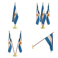
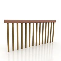
Nasa hand rail from argentina
by GrabCAD
Last crawled date: 1 year, 11 months ago
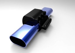
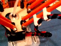
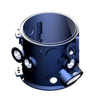
Ok, I finally had time to continue with the design, it is still a work in progress but much closer to the final design.
As you can see, it is quite intricate, but that's not a problem for 3D printing, and this is the explanation why the complexity of the design:
-First, Meets all requirements of the challenge, both in shape, size, dimensions, not elements such pins or bolts are needed very little support is required for printing and no special tools are required. (on this point have some doubts, since it is necessary to remove the support material in any way and can not be done by hand. My greatest concern are the particles and chips that may be loose in space microgravity).
-Second, The lever mechanism is to ensure rapid assembly and disassembly, and a secure fit that does not allow the movement of the clamp along the rail.
-Thirdly, the complexity of the geometry, it is because I paid special attention to that there are no tensile stress in the printing z axis or shear stresses in the xy plane.
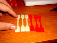
Some time ago I conducted a study of the behavior of 3D printed parts according to ASTM D638 Tensile Strength Plastic Test. My conclusions were that the printed pieces in 3D with FDM technology, do not take load in the axial direction of the printing (Z), it was not possible for me not even take a reference value for this type of load.
On the other hand, I managed to see that besides the orientation of the direction of printing, the amount of solid layers in the wall of the piece is what most influences the ultimate strength of the piece. The fill percentage practically does not change the value.
It is because of this that it is very difficult to to perform a FEA since the printed piece behaves in a very anisotropic way.
Here is the video on youtube of tensile tests of 3D printed probes.
http://youtu.be/zXoISmNSXQ4
I already machined a handrail sector according to specified dimensions, the next step will be print a clamp to check interference, fits, dimensions, etc. and modify the interface according to the seat trak stud, and then upload the final design.
I hope to have time to do some actual strength tests of the final design, gripped to the rail and check how close my design is to the reference values for the aluminum clamp.
Hope you like it!
As you can see, it is quite intricate, but that's not a problem for 3D printing, and this is the explanation why the complexity of the design:
-First, Meets all requirements of the challenge, both in shape, size, dimensions, not elements such pins or bolts are needed very little support is required for printing and no special tools are required. (on this point have some doubts, since it is necessary to remove the support material in any way and can not be done by hand. My greatest concern are the particles and chips that may be loose in space microgravity).
-Second, The lever mechanism is to ensure rapid assembly and disassembly, and a secure fit that does not allow the movement of the clamp along the rail.
-Thirdly, the complexity of the geometry, it is because I paid special attention to that there are no tensile stress in the printing z axis or shear stresses in the xy plane.
Some time ago I conducted a study of the behavior of 3D printed parts according to ASTM D638 Tensile Strength Plastic Test. My conclusions were that the printed pieces in 3D with FDM technology, do not take load in the axial direction of the printing (Z), it was not possible for me not even take a reference value for this type of load.
On the other hand, I managed to see that besides the orientation of the direction of printing, the amount of solid layers in the wall of the piece is what most influences the ultimate strength of the piece. The fill percentage practically does not change the value.
It is because of this that it is very difficult to to perform a FEA since the printed piece behaves in a very anisotropic way.
Here is the video on youtube of tensile tests of 3D printed probes.
http://youtu.be/zXoISmNSXQ4
I already machined a handrail sector according to specified dimensions, the next step will be print a clamp to check interference, fits, dimensions, etc. and modify the interface according to the seat trak stud, and then upload the final design.
I hope to have time to do some actual strength tests of the final design, gripped to the rail and check how close my design is to the reference values for the aluminum clamp.
Hope you like it!
Similar models
grabcad
free

NASA CHAMP by Anders Olsson
...cept, which actually does work, but requires further design efforts when it comes to optimizing dimensions for printing and such.
grabcad
free

Tensile Test Machine
...tensile test machine
grabcad
this machine is very excellent for to know tensile strength work piece
thingiverse
free

Tension Test, Stresstest by skankhunt_42
...ifferent filaments, so i printed it standing up.
to measure the load i use a spring scale. i got values between 7-15kg (69-147n).
thingiverse
free
Tensile Test Subject by MelerineTechnologies
...ith a homebuilt tensile strength tester. the research project for which this machine and test subject were used is also attached.
thingiverse
free
Go Discover Plane (hobby king) motor mount by beardyblair
...parts of the model to provide additional strength where needed. the test printed part fitted perfectly and has been in use since.
thingiverse
free

tensile testing sample (ASTM D638 ; type I)
...tensile testing sample (astm d638 ; type i)
thingiverse
tensile sample for you to 3d print and test the strength of the material
thingiverse
free
ASTM D638 Type I Tensile Bar by koochdawg
...t. created and printed this in hope to test the difference in tensile strengths of a 3d printed material vs. an injection molded.
thingiverse
free
Deltaprintr Strud clamp by matschi
... see the pictures for the dimensions.
i printed it at 50mm/s 100%infill
also did a scale in z-axis by 3 times see second picture
grabcad
free

Tensile Strength Testing
...tensile strength testing
grabcad
tensile strength testing
thingiverse
free
Tensile test specimen by obijuan
...bs, pla...)
more information (in spanish) :http://www.iearobotics.com/wiki/index.php?title=probeta_para_pruebas_de_tracci%c3%b3n
Nasa
turbosquid
$49
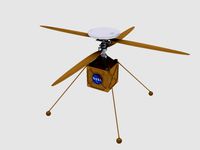
Nasa Marscopter
...id
royalty free 3d model nasa marscopter for download as max on turbosquid: 3d models for games, architecture, videos. (1323349)
turbosquid
$500
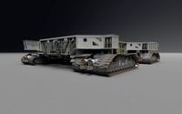
NASA Crawler
... available on turbo squid, the world's leading provider of digital 3d models for visualization, films, television, and games.
turbosquid
$5

Nasa Rocket
... available on turbo squid, the world's leading provider of digital 3d models for visualization, films, television, and games.
turbosquid
$1
NASA Spool.max
... available on turbo squid, the world's leading provider of digital 3d models for visualization, films, television, and games.
3d_export
$15

US NASA 3D Model
...us nasa 3d model
3dexport
spaceship ship nasa battle blender
us nasa 3d model antonielfelain 96625 3dexport
turbosquid
$99
NASA MIT Wing
...oyalty free 3d model nasa mit wing for download as ma and max on turbosquid: 3d models for games, architecture, videos. (1510099)
turbosquid
$29
NASA Electronic Telescope
... available on turbo squid, the world's leading provider of digital 3d models for visualization, films, television, and games.
turbosquid
$6

Real flag NASA
... available on turbo squid, the world's leading provider of digital 3d models for visualization, films, television, and games.
3d_export
$41
NASA FAST Satellite 3D Model
...odel
3dexport
nasa space satellite earth aurora sensor panel solar orbit
nasa fast satellite 3d model visualmotion 20244 3dexport
3d_export
$20

22k photorealistic earth - nasa
...tures directly from nasa.<br>nasa solar system bundle coming soon!<br>contact info@teichmanmedia.eu for all iquiries.
Argentina
turbosquid
$3

argentina
... available on turbo squid, the world's leading provider of digital 3d models for visualization, films, television, and games.
3d_export
$10

Booth Argentina
...booth argentina
3dexport
bootu 10x5
turbosquid
$29

Soccerball Argentina
... available on turbo squid, the world's leading provider of digital 3d models for visualization, films, television, and games.
turbosquid
$29

Soccerball Argentina
... available on turbo squid, the world's leading provider of digital 3d models for visualization, films, television, and games.
turbosquid
$1

Flag of Argentina
...flag of argentina for download as max, 3ds, dxf, fbx, and obj on turbosquid: 3d models for games, architecture, videos. (1594544)
3d_export
$39
argentina flag pack
...argentina flag pack
3dexport
3ddd
$1

sport - shop brasil - argentina
...sport - shop brasil - argentina
3ddd
футболка
sport shop, jerseys brasil - argentina
turbosquid
$40

Political Map of Argentina
... political map of argentina for download as 3ds, max, and obj on turbosquid: 3d models for games, architecture, videos. (1302021)
turbosquid
$18

Animated Argentina Waving Flag
...- bandera de argentina for download as c4d, 3ds, fbx, and obj on turbosquid: 3d models for games, architecture, videos. (1544390)
turbosquid
$1

Volleyball ball Argentina
...leyball ball argentina for download as 3ds, max, obj, and fbx on turbosquid: 3d models for games, architecture, videos. (1200900)
Rail
3d_ocean
$5
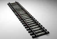
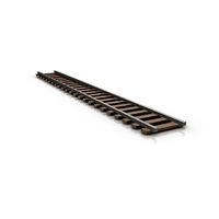
rails
...rails
3docean
old rails rails sleepers
old rails
archibase_planet
free
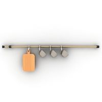
Rail
...chibase planet
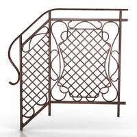
rail railing handrail guard-rail
rail forged fence n310814 - 3d model (*.gsm+*.3ds) for exterior 3d visualization.
archibase_planet
free
Rail
...rail
archibase planet
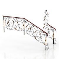
handrail railing guard-rail
rail n220914 - 3d model (*.gsm+*.3ds) for interior 3d visualization.
archibase_planet
free
Rail
...rail
archibase planet
railing hand-rail banisters
rail n130309 - 3d model (*.gsm+*.3ds) for interior 3d visualization.
archibase_planet
free
Rail
...rail
archibase planet
railing hand-rail banisters
rail n270510 - 3d model (*.gsm+*.3ds) for interior 3d visualization.
archibase_planet
free
Railing
...
archibase planet
railing handrail fence guard-rail
railing n140314 - 3d model (*.gsm+*.3ds+*.max) for exterior 3d visualization.
archibase_planet
free
Railing
...railing
archibase planet
railing
railing- 3d model (*.gsm+*.3ds) for interior 3d visualization.
archibase_planet
free
Railing
...railing
archibase planet
railing enclosure barrier
light railing - 3d model for interior 3d visualization.
archibase_planet
free
Rail
...rail
archibase planet
metal railing
rail n280608 - 3d model (*.gsm+*.3ds) for interior 3d visualization.
archibase_planet
free
Railing
...railing
archibase planet
railing kitchen ware
railing 1 - 3d model (*.gsm+*.3ds) for interior 3d visualization.
Hand
3d_export
$8

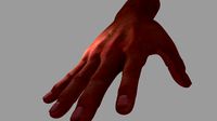
hand
...hand
3dexport
fantasy hand
3d_export
$5
hand
...hand
3dexport
male hand
3d_export
$5
hand
...hand
3dexport
realistic male hand
3d_export
$5

hand
...hand
3dexport
hand with nails and structure
archibase_planet
free
Hand
...hand
archibase planet
hand
hand n190111 - 3d model (*.gsm+*.3ds) for interior 3d visualization.
3ddd
$1

Hand
...hand
3ddd
hand
модель руки будды
3d_export
$5

hand
...hand
3dexport
it is my wrist of hand and this is on 3d sculpt
3d_export
$5
hand
...hand
3dexport
realistic male hand obj file
3d_export
$7
hand-006 rigged hand
...hand-006 rigged hand
3dexport
rigged right hand 3d model additional textures for pbr rendering included
3d_ocean
$6
Hand
...
this 3d models of the hands, made in 3ds max, has textures(.jpg), materials(.mat), rigged, the models in .max, fbx, obj format.