GrabCAD

NASA CHALLENGE - HANDRAIL CLAMP ASSEMBLY
by GrabCAD
Last crawled date: 1 year, 11 months ago
HANDRAIL CLAMP ASSEMBLY (HCA) DESCRIPTION
In the design of the handrail clamp, the following points were taken into consideration in their order of importance.
1. Safety
a. Sharp edge human factors were carefully adhered to as per CHAMP requirements with all edges rounded to appropriate radii
b. A rigid connection between the clamp and rail was vital as described under point 2 below.
2. Function & strength
a. It was deemed of paramount importance that the assembly has a positive grip on the rail. This point is interleaved with Safety as sudden slippage or opening of the bracket is considered unsafe for the astronaut. This would be quite easily achieved with a 3 or 4 piece assembly by using cams, as is the case with the ISS current clamp assembly for example.
This design has two parts (see point 3) and this was achieved by a design with spiral cam arrangement explained below. The object was to achieve rigidity of the clamp-rail connection at least to the level of the rail interface strength achievable with the ABS printed part.
3. Mass and form
It was decided to limit the assembly to two printed parts for simplicity of assembly for minimum astronaut time.
The shape envelope of 1” around the rail has been not been exceeded.
The volume of the HCA assembly is 4.45 in³.
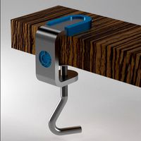
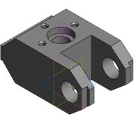
Figure 01 shows the HCA assembly just before the lock nut is turned to tighten the grip around the rail.
Figure 02 is a view behind the lock nut.
Figure 03 shows the HCA assembly with the nut in the LOCK position.
Figure 04 shows the L-Track snapped onto the rail and the lock nut prior to clipping onto the spiral ears. The lock nut has corresponding spirals and pulls the ears together during the 90 degree locking turn.
Figures 05 and 06 show the L-Track body and the lock nut disassembled.
Figure 07 shows a detail of the lock nut interface. The spiral surfaces of the ears and lock nut taper out away from the L-Track thereby preventing the lock nut from being pulled off the assembly.
Figure 08 shows a cross sectional view of the HCA assembly through the center of the lock nut.
The z-axis printing of the L-Track is in the rail direction and the lock-nut z-axis is along its axis. There is practically no scaffolding material due to the 45 degree angle printing rule.
The lock nut has a larger hole next to the rail than further away from it. Similarly, the clamp widens away from the rail. This results in a conical fit and the lock nut is snapped on and is free to rotate when it comes against the clamp until it is rotated into a locked position. In other words, the two parts have a conical fit that would require the lock nut to be pulled and snapped off with a force.
This will make sense if one observes the cross-section renderings above where the 1 degree taper can easily be seen.
Both parts comply with the maximum print size of 2.36” x 2.36” x 4.72”.
In the design of the handrail clamp, the following points were taken into consideration in their order of importance.
1. Safety
a. Sharp edge human factors were carefully adhered to as per CHAMP requirements with all edges rounded to appropriate radii
b. A rigid connection between the clamp and rail was vital as described under point 2 below.
2. Function & strength
a. It was deemed of paramount importance that the assembly has a positive grip on the rail. This point is interleaved with Safety as sudden slippage or opening of the bracket is considered unsafe for the astronaut. This would be quite easily achieved with a 3 or 4 piece assembly by using cams, as is the case with the ISS current clamp assembly for example.
This design has two parts (see point 3) and this was achieved by a design with spiral cam arrangement explained below. The object was to achieve rigidity of the clamp-rail connection at least to the level of the rail interface strength achievable with the ABS printed part.
3. Mass and form
It was decided to limit the assembly to two printed parts for simplicity of assembly for minimum astronaut time.
The shape envelope of 1” around the rail has been not been exceeded.
The volume of the HCA assembly is 4.45 in³.
Figure 01 shows the HCA assembly just before the lock nut is turned to tighten the grip around the rail.
Figure 02 is a view behind the lock nut.
Figure 03 shows the HCA assembly with the nut in the LOCK position.
Figure 04 shows the L-Track snapped onto the rail and the lock nut prior to clipping onto the spiral ears. The lock nut has corresponding spirals and pulls the ears together during the 90 degree locking turn.
Figures 05 and 06 show the L-Track body and the lock nut disassembled.
Figure 07 shows a detail of the lock nut interface. The spiral surfaces of the ears and lock nut taper out away from the L-Track thereby preventing the lock nut from being pulled off the assembly.
Figure 08 shows a cross sectional view of the HCA assembly through the center of the lock nut.
The z-axis printing of the L-Track is in the rail direction and the lock-nut z-axis is along its axis. There is practically no scaffolding material due to the 45 degree angle printing rule.
The lock nut has a larger hole next to the rail than further away from it. Similarly, the clamp widens away from the rail. This results in a conical fit and the lock nut is snapped on and is free to rotate when it comes against the clamp until it is rotated into a locked position. In other words, the two parts have a conical fit that would require the lock nut to be pulled and snapped off with a force.
This will make sense if one observes the cross-section renderings above where the 1 degree taper can easily be seen.
Both parts comply with the maximum print size of 2.36” x 2.36” x 4.72”.
Similar models
grabcad
free

NASA CHALLENGE - HANDRAIL CLAMP ASSEMBLY
...and proved satisfactory in tests on actual printed assemblies. similary, the latch spring thickness was determined during tests. these...
grabcad
free

Nasa hand rail clamp assembly
...sed by astronauts on iss to provide rigid mounting locations required in a microgravity environment for normal daily operations.
grabcad
free

NASA Handrail Clamp Assembly
..._part_volume.pdf.
7. overall dimensions for assembly in open state, along:
x axis - 64 mm
y axis - 57.1 mm
z axis - 59.5 mm
.
grabcad
free

NASA Handrail Clamp Assembly lightweight
...art_material_volumes.pdf.
7. overall dimensions for assembly in open state, along:
x axis - 64 mm
y axis - 57.1 mm
z axis - 54 mm
grabcad
free

GCHAMP
...“locking nut” that has an integral l-track connection point as seen in figure 1. further information is in the uploaded word doc.
grabcad
free

NASA Handrail Clamp Assembly (CHAMP)
...ction:
print each component in vertical axis or along the longest axis of the rail.
i gave my design a name, “bulldog clamp” :-p
grabcad
free

Muhammad Ali (The CHAMP)
...s. it is reasonable to assume if the entire clamp and lock nut assembly was printed at 100% infill it will support a larger load.
grabcad
free

Reuleaux Triangle NASA CHAMP v1.0 and v2.0 (latest)
...functional connection points. the proposed design is using a similar to the hca opposite-to-opening locking mechanism. the decision is...
grabcad
free

GCHAMP HD
...once the locking nut is rotated the fixture is “clamped” when the indents’ inside the nut “set” more information in the documents
grabcad
free

NASA Handrail Clamp Assembly (CHAMP)
...asa
update:- this version has a provision to unhook the upper clamp by simply pressing the handles. now its more simpler to use.
Handrail
3d_export
$5
handrail
...handrail
3dexport
handrail
3d_export
free
handrail
...handrail
3dexport
handrail
archibase_planet
free

Handrail
...handrail
archibase planet
handrail railing guard-rail
handrail n270913 - 3d model (*.gsm+*.3ds) for interior 3d visualization.
archibase_planet
free
Handrail
...l
archibase planet
handrail railing guard-rail
handrail for stair n020813 - 3d model (*.gsm+*.3ds) for interior 3d visualization.
archibase_planet
free
Handrail
...drail
archibase planet
handrail railing guard-rail
handrail stair n030114 - 3d model (*.gsm+*.3ds) for interior 3d visualization.
archibase_planet
free
Handrail
...handrail
archibase planet
railing handhold parapet
handrail n050710 - 3d model (*.3ds) for interior 3d visualization.
archibase_planet
free
Handrail
...handrail
archibase planet
banisters railing guard-rail
handrail n070710 - 3d model (*.3ds) for interior 3d visualization.
archibase_planet
free
Handrail
...handrail
archibase planet
banisters hand-rail railing
handrail n020710 - 3d model (*.gsm+*.3ds) for interior 3d visualization.
archibase_planet
free

Handrail vase
...se planet
handrail vase flower handrail vase
handrails vase n180813 - 3d model (*.gsm+*.3ds+*.max) for exterior 3d visualization.
3ddd
$1
Handrail 1
...handrail 1
3ddd
перила
wooden handrail old style
Nasa
turbosquid
$49
Nasa Marscopter
...id
royalty free 3d model nasa marscopter for download as max on turbosquid: 3d models for games, architecture, videos. (1323349)
turbosquid
$500
NASA Crawler
... available on turbo squid, the world's leading provider of digital 3d models for visualization, films, television, and games.
turbosquid
$5

Nasa Rocket
... available on turbo squid, the world's leading provider of digital 3d models for visualization, films, television, and games.
turbosquid
$1
NASA Spool.max
... available on turbo squid, the world's leading provider of digital 3d models for visualization, films, television, and games.
3d_export
$15
US NASA 3D Model
...us nasa 3d model
3dexport
spaceship ship nasa battle blender
us nasa 3d model antonielfelain 96625 3dexport
turbosquid
$99

NASA MIT Wing
...oyalty free 3d model nasa mit wing for download as ma and max on turbosquid: 3d models for games, architecture, videos. (1510099)
turbosquid
$29
NASA Electronic Telescope
... available on turbo squid, the world's leading provider of digital 3d models for visualization, films, television, and games.
turbosquid
$6

Real flag NASA
... available on turbo squid, the world's leading provider of digital 3d models for visualization, films, television, and games.
3d_export
$41
NASA FAST Satellite 3D Model
...odel
3dexport
nasa space satellite earth aurora sensor panel solar orbit
nasa fast satellite 3d model visualmotion 20244 3dexport
3d_export
$20

22k photorealistic earth - nasa
...tures directly from nasa.<br>nasa solar system bundle coming soon!<br>contact info@teichmanmedia.eu for all iquiries.
Challenge
turbosquid
$120
Challenger 2 and challenger 2 TES
...e 3d model challenger 2 and challenger 2 tes for download as on turbosquid: 3d models for games, architecture, videos. (1430319)
3d_export
$59

dodge challenger srt8
...dodge challenger srt8
3dexport
dodge challenger srt8
3d_export
$20

dodge challenger 1970
...dodge challenger 1970
3dexport
dodge challenger 1970
3d_export
$15
Dodge Challenger Hellcat
...dodge challenger hellcat
3dexport
dodge challenger hellcat
turbosquid
$80
challenger-2
...rbosquid
royalty free 3d model challenger-2 for download as on turbosquid: 3d models for games, architecture, videos. (1498848)
3d_export
$5

dodge challenger car
...dodge challenger car
3dexport
3d model dodge challenger!
turbosquid
$99
Dodge Challenger
...
royalty free 3d model dodge challenger for download as blend on turbosquid: 3d models for games, architecture, videos. (1489358)
turbosquid
$49

Dodge Challenger
...
royalty free 3d model dodge challenger for download as blend on turbosquid: 3d models for games, architecture, videos. (1698375)
turbosquid
$10

dodge challenger
...
royalty free 3d model dodge challenger for download as blend on turbosquid: 3d models for games, architecture, videos. (1405948)
3d_export
free

dodge challenger srt8
...dodge challenger srt8
3dexport
dodge challenger srt8 free model
Clamp
3d_export
$11

clamp
...clamp
3dexport
clamp
3ddd
free

Clamp
... enricо zanolla , капитоне
дизайнерenrico zanollмодель clamp
3ddd
$1

Clamp
...ricо zanolla , капитоне
дизайнеры
enrico zanolla
andrea di filippo
модель clamp
dzstudio
3d_export
free
clamp
...clamp
3dexport
simple clamp model, more free 3d models here:
3d_export
$5
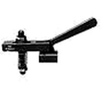
clamping handle
...clamping handle
3dexport
clamping handle
3ddd
$1

Clamp / DZstudio
... dzstudio , капитоне
люстра clamp от dzstudio/enrico zanolla(италия).
3ddd
$1
Светильник Clamp
...светильник clamp
3ddd
clamp
стеганый светильник clamp в двух цветах в черном и белом.
turbosquid
$29
clamp
...ty free 3d model clamp for download as 3ds, obj, c4d, and fbx on turbosquid: 3d models for games, architecture, videos. (1442049)
turbosquid
$29

clamp
...ty free 3d model clamp for download as 3ds, obj, c4d, and fbx on turbosquid: 3d models for games, architecture, videos. (1442041)
3d_export
$5
Clamp-14
...clamp-14
3dexport
3d model of clamp name 14
Assembly
3d_export
$7
Electronic product assembly machine assembly machine
...electronic product assembly machine assembly machine
3dexport
electronic product assembly machine assembly machine
3d_export
$15
generator assembly line
...ced and assembled in the form of module block. it is a demonstration project of generator assembly. welcome to download and learn
3d_export
$10
elevator traction machine assembly line motor assembly process
... traction machine assembly line motor assembly process
3dexport
elevator traction machine assembly line (motor assembly process)
3d_export
$16
pin assembly machine
...pin assembly machine
3dexport
pin assembly machine
3d_export
$7
tower-crane-assembly
...tower-crane-assembly
3dexport
tower-crane-assembly
turbosquid
$100

Engine Assembly
...id
royalty free 3d model engine assembly for download as stl on turbosquid: 3d models for games, architecture, videos. (1658296)
turbosquid
$100
Engine Assembly
...id
royalty free 3d model engine assembly for download as stl on turbosquid: 3d models for games, architecture, videos. (1658291)
turbosquid
$100

Engine Assembly
...id
royalty free 3d model engine assembly for download as stl on turbosquid: 3d models for games, architecture, videos. (1658293)
turbosquid
$75
Platform Assembly
...royalty free 3d model platform assembly for download as blend on turbosquid: 3d models for games, architecture, videos. (1472939)
turbosquid
$15
generator assembly
...y free 3d model generator assembly for download as and sldas on turbosquid: 3d models for games, architecture, videos. (1469469)